16 years one-stop China custom CNC machining parts factory

Hey there I’m VMT Sam!
With 25 years of CNC machining experience we are committed to helping clients overcome 10000 complex part-processing challenges all to contribute to a better life through intelligent manufacturing. Contact us now
 1567 |
Published by VMT at Jan 09 2023
1567 |
Published by VMT at Jan 09 2023


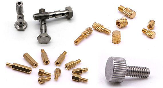
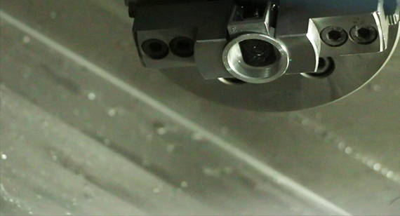
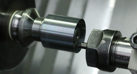
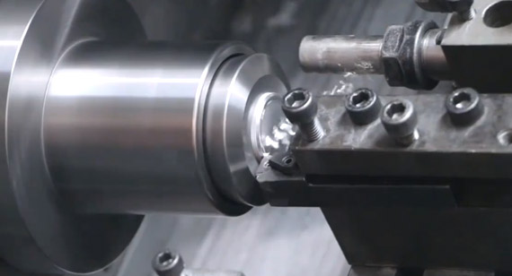
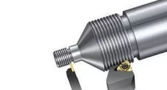
A thread is a continuous protrusion and groove formed along a helix on a cylindrical or conical surface with the same cross-section and specified profile. Among various mechanical products, threaded parts are widely used. It is mainly used as connecting parts, fastening parts, transmission parts and measuring parts, etc. Machining threads on CNC lathes is one of the more commonly used processing methods. Thread processing on CNC lathes occupies an increasingly important position in mechanical processing due to its advantages of high processing accuracy, good product uniformity, and wide range of CNC machining. The following content starts from the practical application, and expounds the faults that are prone to occur during the cutting process due to equipment, tools or operators when machining threads on CNC lathes, and their solutions.
Common faults and solutions for CNC turning threads on CNC lathes mainly include:
1. Knife
1.1 Main reasons
(1) The rake angle of the turning tool is too large, and the clearance of the X-axis screw of the machine tool is large;
(2) The turning tool is installed too high or too low;
(3) The workpiece is not firmly clamped;
(4) Excessive wear of the turning tool;
(5) The amount of cutting is too large.
1.2 Solution
(1) Reduce the rake angle of the turning tool, maintain the machine tool to adjust the screw clearance of the X-axis, and use the automatic compensation function of the screw clearance of the CNC lathe to compensate the clearance of the screw clearance of the X-axis of the machine tool;
(2) The turning tool is installed too high or too low: if it is too high, when the knife reaches a certain depth, the flank surface of the turning tool will withstand the workpiece, increasing the friction force, and even bending the workpiece, causing the knife phenomenon; If it is too low, the chips are not easy to discharge. The direction of the radial force of the turning tool is the center of the workpiece. In addition, the gap between the screw and the nut is too large, so that the depth of the knife will automatically tend to deepen continuously, thereby lifting the workpiece and causing knife sticking. At this time, the height of the turning tool should be adjusted in time so that the tool tip is at the same height as the axis of the workpiece (the tip of the tailstock can be used for tool setting). In rough turning and semi-finishing turning, the position of the tool tip is about 1% D higher than the center of the workpiece (D represents the diameter of the workpiece to be processed).
(3) The workpiece is not firmly clamped: the rigidity of the workpiece itself cannot bear the cutting force during turning, so excessive deflection occurs, which changes the center height between the turning tool and the workpiece (the workpiece is raised), resulting in a sudden increase in cutting depth , A stabbing knife appears, at this time the workpiece should be clamped firmly, and the tailstock center can be used to increase the rigidity of the workpiece.
(4) Excessive wear of the turning tool: it causes the cutting force to increase, the workpiece is bent, and the knife appears. At this time, the turning tool should be sharpened.
(5) The cutting amount (mainly the cutting amount and cutting speed) is too large: choose a reasonable cutting amount according to the lead size of the workpiece 5 and the rigidity of the workpiece.
2. Random button
2.1 Fault phenomenon
When the lead screw rotates once, the workpiece does not rotate an integer number of revolutions.
2.2 Main reasons
The synchronous transmission belt of the machine tool spindle encoder is worn, and the synchronous real speed of the spindle cannot be detected; the program compiled and input to the host is incorrect; the X-axis or Y-axis screw is worn.
2.3 Solutions
(1) Spindle encoder synchronous belt wear: Since the movement relationship between the spindle and the turning tool is controlled by the instructions issued by the information processing center of the machine tool host during CNC turning thread, the spindle speed is constant during CNC turning thread, X or The Y-axis can adjust the moving speed according to the size of the workpiece lead and the spindle speed, so the center must detect the real synchronous speed of the spindle to issue correct commands to control the correct movement of the X or Y-axis. If the system cannot detect the real speed of the spindle, it will send different commands to X or Y during actual turning. Then, when the spindle rotates once, the distance the tool moves is not a lead. Will buckle randomly. In this case, we only have to repair the machine tool and replace the main shaft timing belt.
2) The input program is incorrect: in order to prevent random thread turning during CNC turning, it is necessary to ensure that the turning track of the next cutting tool coincides with the turning track of the previous cutting tool. On CNC lathes, we use programs to prevent random buckling, that is, when we compile the processing program, we use the program to control the thread cutter to retreat after the first cut in turning, so that the starting point of the next cutting coincides with the starting point of the previous cutting (equivalent to When the thread is turned by CNC on the ordinary car, the thread cutter returns to the spiral groove formed by the previous knife), so that the thread produced by the car will not be buckled indiscriminately. Sometimes, because the lead of the program input is incorrect (the lead of the next program is inconsistent with the lead of the previous program), chaotic buckling will also occur during turning.
(3) The X-axis or Y-axis screw is seriously worn: repair the machine tool and replace the X-axis or Z-axis screw.
3. The pitch is incorrect
3.1 Main reasons
The data sent back to the machine tool system by the spindle encoder is inaccurate; the movement of the X-axis or Y-axis screw and the spindle is too large; the program compiled and input is incorrect.
3.2 Solutions
(1) The data transmitted by the spindle encoder is inaccurate: repair the machine tool, replace the spindle encoder or the synchronous transmission belt;
(2) The X-axis or Y-axis screw and the main shaft move too much: adjust the axial movement of the main shaft, and the clearance of the X-axis or Y-axis screw can be compensated by the automatic compensation function of the system clearance;
(3) Check the program to make sure that the instruction lead in the program is consistent with the drawing requirements.
4. Tooth type is not correct
4.1 Main reasons
The tip of the turning tool is not sharpened correctly; the turning tool is not installed correctly; the turning tool is worn.
4.2 Solutions
(1) The sharpening of the turning tool tip is not correct: correctly sharpen and measure the turning tool tip angle. For thread turning that requires high profile angle accuracy, standard mechanical clamping thread cutters can be used for turning, or the thread The knife is sharpened with a grinder.
(2) The turning tool is installed incorrectly: when installing the tool, use a template to set the tool, or use a dial indicator to align the threaded tool holder to install the threaded tool.
(3) Turning tool wear: According to the actual situation of CNC turning, the cutting amount should be selected reasonably, and the turning tool should be sharpened in time.
5. Analysis of large faults on thread surface roughness
5.1 Main reasons
Built-up edge occurs on the tip of the tool; the rigidity of the tool handle is not enough, and vibration occurs during cutting; the radial rake angle of the turning tool is too large; when cutting threads at high speed, the cutting thickness is too small or the chips are discharged in an inclined direction, and the surface of the machined flank is roughened; The rigidity is poor, and the cutting amount is too large; the surface roughness of the turning tool is poor.
5.2 Solutions
(1) When cutting with high-speed steel turning tools, the cutting speed should be reduced, and the cutting fluid should be selected correctly;
(2) Increase the cross-section of the handle and reduce the extension length of the handle;
(3) Reduce the radial rake angle of the turning tool;
(4) When cutting threads with high-speed steel, the chip thickness of the last cut is generally greater than 0.1mm, and the chips are discharged along the vertical axis;
(5) Choose a reasonable cutting amount;
(6) The surface roughness of the cutting edge of the tool should be 2-3 grades smaller than the surface roughness value of the CNC parts.
In short, there are various types of faults that occur during CNC turning threads, including equipment reasons, tools, operators, etc. When troubleshooting, it is necessary to analyze the specific situation and find out the specific faults through various detection and diagnostic methods. influence factors and take effective solutions.

 +86 15099911516


 Read more