16 years one-stop China custom CNC machining parts factory

Hey there I’m VMT Sam!
With 25 years of CNC machining experience we are committed to helping clients overcome 10000 complex part-processing challenges all to contribute to a better life through intelligent manufacturing. Contact us now
 3357 |
Published by VMT at Jul 04 2025 | Reading Time:About 5 minutes
3357 |
Published by VMT at Jul 04 2025 | Reading Time:About 5 minutes


In precision manufacturing and engineering, achieving the right fit between components is crucial. However, many professionals and customers struggle to fully grasp what “fit H7” means and why it matters. This confusion often leads to miscommunication, incorrect machining tolerances, and costly rework. Understanding the concept of fit H7—and how it relates to tolerances, limits, and fits—is essential for ensuring parts meet design specifications and function reliably. This article addresses this challenge by clarifying the fundamentals of fit H7, its tolerance values, and practical applications, helping engineers and manufacturers avoid costly errors.
Fit H7 is a standard tolerance grade for holes commonly used in CNC machining parts and assemblies. It specifies the permissible size variation with a zero lower deviation and a positive upper deviation depending on the nominal size. Understanding H7 tolerance ensures precise component fits, improving product quality and performance in CNC machining factories.
To fully appreciate the significance of fit H7, it is important to first understand what “fit” and “tolerance” mean in engineering contexts. This article will explore these concepts, detail the tolerance grades for H7, and explain the difference between H7 and H7 fit. Furthermore, practical applications of fit H7 in CNC machining services will be discussed, guiding readers toward making informed decisions in manufacturing.
Key Points
Fit H7 is a specific designation in the ISO system of limits and fits, describing a tolerance grade primarily applied to holes. It ensures that the hole size remains within a defined tolerance zone where the lower limit is exactly equal to the nominal size (0 μm deviation), and the upper limit allows for a positive deviation. This positive deviation varies depending on the nominal diameter of the hole, which means that as the hole size increases, the permissible tolerance range increases accordingly. This system guarantees that the hole will never be smaller than its nominal size, which is critical for assembly purposes where precise clearances or interference fits are required.

The term "fit H7" refers to the standardized tolerance for holes where the 'H' indicates the position of the tolerance zone relative to the nominal size and the '7' defines the tolerance grade or size of the tolerance range. In the case of 'H7,' the tolerance zone starts at zero deviation from the nominal dimension, meaning the hole size will not be smaller than the nominal dimension but can be slightly larger, within defined limits. This ensures a consistent and predictable fit between the hole and its mating shaft or component, which is vital in CNC machining services for ensuring parts fit together correctly without excessive looseness or tightness.
Tolerance in engineering refers to the permissible limit or limits of variation in a physical dimension of a manufactured part. It defines how much a dimension can deviate from the nominal value and still function correctly within an assembly. Proper tolerance specification balances manufacturing costs and functional requirements. Too tight a tolerance increases production difficulty and cost, while too loose a tolerance can lead to poor performance or assembly failures. In CNC machining parts manufacturing, understanding and applying the correct tolerance—like the H7 tolerance—is critical for producing parts that meet design intent and quality standards.

The H7 tolerance defines the acceptable size variation for holes, with the lower limit always set at the nominal size (0 μm deviation) and the upper limit varying according to the nominal hole size. This graded approach allows for consistent manufacturing practices while maintaining high precision.
| Nominal Size Range (mm) |
Lower Limit (μm) |
Upper Limit (μm) |
| 1 – 3 | 0 | +10 |
| >3 – 6 | 0 | +12 |
| >6 – 10 | 0 | +15 |
| >10 – 18 | 0 | +18 |
| >18 – 30 | 0 | +21 |
| >30 – 50 | 0 | +25 |
H7 tolerance specifies the allowable dimensional deviation for holes, where the hole diameter cannot be smaller than the nominal size but can be larger up to the tolerance upper limit. This ensures that parts such as shafts and pins will fit properly without risk of jamming or excessive clearance. H7 tolerance is commonly applied in the production of CNC machining parts, offering a good balance between precision and manufacturability.
The tolerance value for H7 depends on the nominal size of the hole. For example, a nominal hole size between 10 mm and 18 mm has an H7 tolerance of 0 to +18 μm. This means the hole can measure anywhere from exactly 10.000 mm up to 10.018 mm, ensuring precise fit with mating parts.
Achieving the precise H7 tolerance in CNC machining parts is a critical step that directly impacts product quality, assembly accuracy, and overall manufacturing efficiency. H7 tolerance demands that hole diameters maintain a strict size range—starting exactly at the nominal dimension (zero lower deviation) and allowing only a slight positive deviation defined by the tolerance grade. Meeting this requirement involves a combination of advanced technology, skilled craftsmanship, and rigorous quality control, all of which are core strengths of leading CNC machining factories like VMT.
Precision Equipment and Tooling
The foundation for achieving H7 tolerance lies in the selection and use of high-precision machining equipment. Modern CNC machines, equipped with computer-controlled cutting tools and real-time feedback systems, enable manufacturers to maintain tight dimensional control. For holes requiring H7 tolerance, tools such as precision drills and reamers calibrated to the H7 specifications are essential. These tools minimize cutting errors and help produce holes with smooth surfaces and accurate diameters.
Controlled Machining Processes
Consistent machining parameters are vital. This includes controlling spindle speed, feed rate, and cutting depth, which directly affect the dimensional accuracy and surface finish of the hole. Optimizing these parameters reduces tool wear and thermal distortion—both of which can cause deviations outside the H7 tolerance. Experienced operators and advanced CNC programming further ensure that each hole adheres to the required limits.
Heat Treatment and Material Stability
Some materials may experience dimensional changes due to residual stress or thermal expansion during machining. Proper heat treatment and controlled cooling processes help stabilize material dimensions before and after machining, preventing unwanted size variations that could violate H7 tolerance limits.
Inspection and Quality Control
Achieving H7 tolerance is incomplete without stringent inspection. CNC machining factories employ advanced measurement technologies such as Coordinate Measuring Machines (CMMs), laser scanners, and plug gauges to verify hole sizes with micron-level accuracy. Real-time inspection during production allows for immediate adjustments, ensuring every batch consistently meets the H7 tolerance standard.
Skilled Workforce and Continuous Improvement
Behind every perfectly machined part lies the expertise of skilled engineers and machinists who understand the nuances of achieving tight tolerances. Continuous training and process optimization help factories like VMT maintain high-quality standards and deliver CNC machining parts that meet or exceed client expectations.
In summary, achieving H7 tolerance requires the integration of precise machinery, controlled processes, stable materials, and rigorous quality assurance. By leveraging these capabilities, CNC machining services can produce parts that fit perfectly, ensuring smooth assembly and reliable performance in demanding applications. Choosing a professional CNC machining factory experienced in maintaining H7 tolerance, such as VMT, guarantees the accuracy and consistency your projects demand.
In the realm of precision engineering and CNC machining, the terms H7 and H7 fit are often used, but they represent related yet distinct concepts. Understanding the difference is essential for manufacturers and engineers to ensure proper part assembly and functionality.
What Does H7 Mean?
H7 specifically refers to a tolerance grade for holes according to the ISO system of limits and fits. It defines the allowable size variation for a hole relative to its nominal dimension. The key feature of an H7 tolerance is that the lower limit deviation is zero, meaning the hole size will never be smaller than the nominal dimension. The upper limit deviation varies depending on the hole’s nominal size but generally allows a small positive tolerance. For example, a 10 mm hole with H7 tolerance might range from exactly 10.000 mm to 10.015 mm.
In practical terms, when someone says "H7 tolerance," they are referring to the specific allowable dimensional variation of a hole.
What Is H7 Fit?
The term H7 fit goes a step further. It usually refers to the combination of a hole with H7 tolerance and a shaft tolerance (often something like h6 or g6) to form a specific type of fit between the two parts. This fit determines how tightly or loosely the shaft will fit into the hole.
When someone mentions an "H7 fit," they are typically describing a matched pair of hole and shaft tolerances designed to achieve a specific functional fit, such as a sliding or press fit.
Why Does This Matter?
For CNC machining services and manufacturing, knowing the difference is crucial for:
When VMT CNC machining factories refer to H7 or H7 fits, they provide parts that meet the precise requirements, ensuring your assemblies work as intended, whether it’s a loose clearance or a tight interference fit.
In summary, H7 refers to the tolerance specification of a hole, while H7 fit describes the combined tolerance pairing of a hole (H7) and a shaft, determining the type of fit between two mating parts.
In precision engineering and CNC machining, tolerance grades are standardized classifications that define the acceptable limits of variation in the dimensions of manufactured parts. These grades are critical because no machining process can produce parts with absolute perfection. Tolerance grades specify how much a dimension can deviate from its nominal (ideal) value without affecting the part’s function.
Why Are Tolerance Grades Important?
Tolerance grades ensure consistency, interchangeability, and proper function in mechanical assemblies. They help manufacturers and engineers communicate clear expectations for quality and precision. Selecting the correct tolerance grade for a part directly impacts:
How Are Tolerance Grades Defined?
Tolerance grades are denoted by numbers that range typically from IT01 (the tightest tolerance) to IT16 (the loosest tolerance), according to the International Tolerance (IT) system established by ISO standards. The smaller the IT number, the more precise the tolerance.
For example:
Relation to Fit Types and Applications
Tolerance grades work hand-in-hand with fits (clearance, transition, interference) to specify the exact relationship between mating parts, such as holes and shafts. For instance, the popular H7 tolerance grade for holes ensures a precise size range that pairs well with shaft tolerances (like h6 or g6) to create specific fit types suitable for different applications.
Tolerance Grades in CNC Machining Services
In the context of CNC machining parts and CNC machining factories, understanding and applying the correct tolerance grades is essential for delivering parts that meet customer requirements. CNC machines are capable of achieving a wide range of tolerance grades, but achieving tighter tolerances (like IT6 or IT7) requires advanced machines, tooling, and skilled operators.
In summary, tolerance grades provide a standardized way to control dimensional accuracy in manufacturing. Choosing the right tolerance grade balances cost and precision, ensuring parts produced by CNC machining services fit perfectly and perform reliably in their intended applications.
Here’s a clear and professional table summarizing Tolerance Grades based on the International Tolerance (IT) system, tailored for CNC machining contexts:
| Tolerance Grade (IT) |
Precision Level |
Typical Applications |
Approximate Tolerance Range (μm) for 10 mm Nominal Size |
| IT01 | Extremely Tight | Ultra-precision components (high-end optics, aerospace) | ~0.3 |
| IT0 | Ultra Tight | Precision instruments, fine mechanical parts | ~0.5 |
| IT1 | Very Tight | Precision bearings, high-accuracy shafts | ~0.8 |
| IT2 | Tight | Precision gears, high-precision CNC machined parts | ~1.2 |
| IT3 | High Precision | Precision mechanical assemblies | ~2.0 |
| IT4 | Precision | General precision engineering | ~3.0 |
| IT5 | Medium Precision | Machine tool components, automotive parts | ~4.5 |
| IT6 | Medium | General engineering parts with moderate accuracy | ~7.0 |
| IT7 | Standard | Common fits such as H7 holes, shafts | ~10 |
| IT8 | Moderate | Components where some clearance or interference allowed | ~14 |
| IT9 | Loose | Non-critical parts, housings, frames | ~21 |
| IT10 | Very Loose | Large assemblies with high clearance | ~30 |
| IT11 | Very Loose | Low precision parts, structural components | ~43 |
| IT12 | Loose | Rough machining, castings | ~60 |
| IT13 | Very Loose | Non-critical large parts | ~85 |
| IT14 | Extremely Loose | Very rough tolerances, basic assemblies | ~120 |
| IT15 | Extremely Loose | Basic rough machining | ~170 |
| IT16 | Maximum Tolerance | Non-machined or very rough parts | ~240 |
Notes:
This table helps CNC machining factories and clients understand the range of tolerance precision achievable and select the right grade for specific applications.
The Hole-Shaft Reference System is a fundamental concept in precision engineering and CNC machining that defines how tolerances are assigned to mating parts — specifically holes and shafts — to achieve desired fits. This system ensures that parts manufactured separately will assemble correctly with the appropriate clearance or interference.
How Does It Work?
The system is based on assigning tolerance zones relative to a nominal dimension for both holes and shafts:
The hole basis system is the most commonly used because it is easier and more cost-effective to produce accurate holes, especially when using CNC machining services.
Notation in the Hole-Shaft System
For example, in an H7/h6 fit:
Why Is This Important?
By combining different hole and shaft tolerance grades and positions, engineers can design fits that satisfy different assembly requirements:
Application in CNC Machining Services
For CNC machining parts and factories, applying the hole-shaft reference system ensures consistent quality and fitment, reducing rework and assembly issues. For example, specifying an H7 tolerance for holes and a matching shaft tolerance guarantees the parts produced meet expected functional requirements.
In summary, the hole-shaft reference system is the backbone of specifying dimensional tolerances and fits between mating parts, vital for reliable performance in mechanical assemblies and CNC machined components.
Here’s a clear and professional table illustrating the Hole-Shaft Reference System, showing common hole and shaft tolerance zones, their notation, and typical fit types used in CNC machining:
| Fit Type |
Hole Tolerance (Uppercase Letter + IT Grade) |
Shaft Tolerance (Lowercase Letter + IT Grade) |
Description |
Typical Application |
| Clearance Fit | H7 | g6 | Shaft is always smaller than hole; easy assembly | Bearings, sliding shafts, general assemblies |
| Clearance Fit | H7 | h6 | Shaft size close to hole size but still clearance | Precision shafts, bearing housings |
| Transition Fit | H7 | k6 | Shaft size may slightly interfere or clear | Precision gears, light press fits |
| Transition Fit | H7 | n6 | Shaft size slightly larger or smaller, tight fit | Couplings, machine parts requiring alignment |
| Interference Fit | H7 | p6 | Shaft larger than hole; requires force assembly | Press fits, shrink fits, locking assemblies |
| Interference Fit | H7 | s6 | Larger shaft, heavy interference fit | Heavy-duty shafts, gear mounting |
Explanation:
H7 is the most common hole tolerance with zero lower deviation and a positive upper deviation defined by IT7, ensuring the hole size is consistent.
Shaft tolerance letters (g, h, k, n, p, s) indicate the position of the shaft tolerance zone relative to the nominal size:
This table helps CNC machining factories and engineers select the proper hole and shaft tolerance combinations for their applications, ensuring parts fit perfectly according to design requirements.
In precision engineering and CNC machining, achieving the right fit between two mating parts is crucial for functionality, durability, and performance. Restrictions and fits define how tightly or loosely these parts fit together, impacting assembly ease, movement, and load transfer. Understanding these concepts helps manufacturers and clients choose the right CNC machining services and parts for their specific needs.

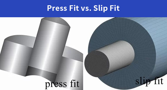
Three Major Fits
There are three primary types of fits used in mechanical design and CNC machining, each with distinct characteristics and applications:
1. Clearance Fit
Clearance fit means there is always a gap between the hole and the shaft, ensuring that the shaft can move freely or slide easily within the hole. This type of fit is commonly used where movement, rotation, or easy assembly/disassembly is needed. The clearance provides space to accommodate minor manufacturing variations and thermal expansion without causing interference or jamming.
2. Transition Fit
Transition fit occurs when the shaft and hole sizes are very close, leading to either a small clearance or slight interference. This fit allows parts to be assembled with minimal force and may require slight adjustment or gentle pressing. It provides a balance between ease of assembly and positional accuracy, often used in precise mechanical systems where alignment is critical.
3. Interference Fit
Interference fit means the shaft is intentionally made larger than the hole, creating a tight assembly that requires force to assemble or disassemble. This fit ensures a secure connection capable of transmitting high loads and resisting relative movement. It is essential for applications where parts must not slip or rotate relative to each other during operation.
Understanding these restrictions and fits is essential when specifying tolerances like the fit H7 in CNC machining parts. Choosing the correct fit type ensures the right balance between ease of assembly, operational stability, and durability in any manufacturing project.
To explore more about specific tolerances and how to achieve them in CNC machining services, readers can continue to other related pages about H7 tolerance and limit and fit systems.
Here’s a clear and professional table summarizing the Three Major Fits in CNC machining, along with their characteristics and typical applications:
| Fit Type |
Description |
Characteristics |
Typical Applications |
| Clearance Fit |
Shaft is always smaller than the hole, allowing free movement and easy assembly | Always a gap; no interference | Bearings, sliding shafts, adjustable assemblies |
| Transition Fit |
Shaft and hole sizes are very close, may result in a small clearance or slight interference | Either a small gap or slight interference | Precision gears, couplings, light press fits |
| Interference Fit |
Shaft is larger than the hole, requiring force to assemble and ensuring a tight, secure connection | Always interference; tight and secure fit | Press fits, shrink fits, gear mounting, locking parts |
This table provides a quick reference for selecting the appropriate fit type based on assembly needs and functional requirements in CNC machining parts and services.
Fit H7 is one of the most widely used tolerance classes in CNC machining, particularly for holes. It specifies a hole with a zero lower deviation and a controlled positive upper deviation, ensuring precise dimensions with consistent quality. This fit is essential in achieving reliable and repeatable assemblies in various industries.
Common Applications of Fit H7
Bearing Seats:
Shaft and Housing Assemblies:
Gear and Pulley Mounts:
Hydraulic and Pneumatic Cylinders:
Automotive and Aerospace Components:
Examples in CNC Machining Services
In summary, Fit H7 plays a critical role in CNC machining parts, offering a balance between manufacturing ease and precision, essential for quality assembly and long-lasting performance.
For more detailed insights on related topics, readers can explore articles about H7 tolerance, limit and fit, and other CNC machining precision standards.
Here's a professional table summarizing Fit H7 Applications and Examples for CNC machining:
| Application Area |
Description |
Typical CNC Machining Parts |
Industry Examples |
| Bearing Seats |
Holes manufactured to H7 tolerance ensure precise bearing fits without excessive clearance or tightness. | 3Cr13 stainless steel CNC machining parts | Automotive, Industrial machinery |
| Shaft and Housing Assemblies |
Ensures reliable, smooth operation with balanced fit between rotating or sliding parts. | 316 stainless steel CNC machining parts | Aerospace, Heavy equipment |
| Gear and Pulley Mounts |
Maintains alignment and reduces vibration for smooth power transmission. | Custom CNC machining parts | Mechanical transmission, Robotics |
| Hydraulic & Pneumatic Cylinders |
Provides tight, leak-free fits for pistons moving within cylinders. | Precision CNC machined cylinder components | Hydraulic systems, Pneumatics |
| Automotive & Aerospace Components |
Critical components requiring high dimensional accuracy for safety and performance. | High-precision CNC machined parts | Automotive, Aerospace industries |
This table helps clients and engineers quickly understand where Fit H7 tolerance is commonly applied and which CNC machining parts benefit most from this precision.
Understanding Fit H7 and its related tolerances is essential for achieving precision and reliability in CNC machining parts. Fit H7 provides a standardized tolerance for holes that balances ease of assembly with functional accuracy, making it one of the most commonly used fits in manufacturing industries such as automotive, aerospace, medical devices, and general machinery.
By mastering the principles of H7 tolerance, manufacturers and engineers can ensure that parts like bearings, shafts, gears, and housings fit together perfectly, reducing wear and tear, improving performance, and lowering production costs. Furthermore, applying the correct fit type—whether clearance, transition, or interference—helps optimize assembly processes and product longevity.
For businesses seeking reliable CNC machining services or factories specializing in precision parts, choosing the right tolerance standards like Fit H7 is a critical step toward superior quality and efficiency. Embracing these standards not only meets engineering requirements but also enhances customer satisfaction and competitive advantage.
To explore more about CNC machining tolerances, fits, and other precision engineering topics, readers are encouraged to review related resources and connect with professional CNC machining factories experienced in delivering parts that meet exacting specifications.

1. What is the tolerance of an H7 reamer?
An H7 reamer provides a hole tolerance where the lower limit is zero deviation and the upper limit varies based on hole size (e.g., +10 µm for 1-3 mm holes). It ensures precise hole dimensions with a tight tolerance range.
2. What do H7 and H8 on a reamer mean?
H7 and H8 indicate the tolerance grade of the hole produced by the reamer. H7 offers tighter tolerance and higher precision compared to H8, which allows a slightly larger clearance.
3. What is a 7 degree reamer?
A 7 degree reamer typically refers to the taper angle of the reamer, which is 7 degrees, used for creating tapered holes.
4. What is a 7 inch 24 taper?
This specifies a taper with 24 threads per inch and a 7-inch length, commonly used in tool holders and machining setups.
5. What is the angle of a reamer?
The cutting angle of a reamer varies but typically ranges between 10 to 20 degrees depending on material and application.
6. How to determine the size of a reamer?
The size corresponds to the nominal diameter of the hole to be finished. It is selected based on the desired hole size and tolerance requirements.
7. What is the tolerance of an H6 thread?
H6 thread tolerance means the hole or shaft size variation is smaller than H7, offering a tighter fit for more precise applications.
8. How to calculate the size of a reamer?
Select the nominal hole size, then consider the tolerance and material allowance. The reamer size typically equals the maximum hole size within the tolerance zone.
9. What is the tolerance of an H6 shank?
An H6 shank has a very tight tolerance, often used for precision shafts requiring minimal clearance.
10. How much material can a reamer remove?
Reamers remove minimal material, usually less than 0.25 mm, to achieve the final hole size and finish.
11. What is the formula for reaming a hole?
Reaming size = drill size + allowance for reaming (usually 0.1 to 0.3 mm depending on material).
12. What is the accuracy of a reamer?
Reamers typically achieve accuracy within 0.01 mm to 0.02 mm, depending on machine and tool condition.
13. What size hole does a 20mm reamer fit?
A 20mm reamer is designed to finish holes approximately 20 mm in diameter with H7 tolerance.
14. What tolerance is acceptable?
Acceptable tolerance depends on application but H7 is a common standard for holes needing precision and interchangeability.
15. How to calculate fit tolerance?
Fit tolerance is calculated by subtracting shaft tolerance limits from hole tolerance limits, defining clearance or interference.
16. What is fit and what types of fits are there?
Fit describes how two mating parts interact—types include clearance fit, transition fit, and interference fit.
17. What is the accuracy of a reamer?
See answer #12: around 0.01 to 0.02 mm accuracy.
18. What is the cut of a reamer?
The cut refers to the reamer’s cutting edges and geometry designed for smooth hole finishing.
19. How to calculate tolerance?
Tolerance = maximum limit – minimum limit of a dimension.
20. What is the tolerance limit allowed?
Limits vary by tolerance grade, with H7 limits ranging from 0 µm up to +25 µm depending on hole size.
21. What does H7 mean in machining?
H7 indicates a hole tolerance grade with zero lower deviation and a defined positive upper deviation, standard for precision holes.
22. What is the difference between H4 and H7 fittings?
H4 is a tighter tolerance than H7, offering less clearance for more precise fits.
23. What is the clearance fit of H7 h6?
H7/h6 is a common clearance fit where the hole is slightly larger than the shaft, allowing smooth assembly with minimal play.
This FAQ section addresses the most common queries about Fit H7 and related machining tolerances, aiding customers and engineers in making informed decisions about CNC machining parts and services.

 +86 15099911516


 Read more