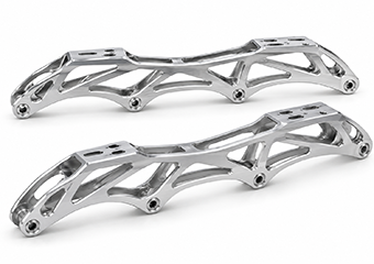
4-Wheel Inline Speed Skate Frames
Custom 4-wheel frames machined around your specified wheel diameter, wheelbase, axle locations, boot interface and weight-reduction geometry.
Request a Quote
Home / Product / Aluminum Parts /
As your aluminum CNC machining manufacturer, we have 40+ aluminum alloy materials, 100 CNC machining equipment, and 12 quality inspection processes. can provide you with a solution tailored to your specific needs.

Product Specification:


VMT manufactures custom inline speed skate frames from your drawings, CAD models and functional requirements. We support prototype validation and OEM production with DFM review focused on axle relationships, boot mounting interfaces, lightweight structures, machining stability, anodizing and critical-feature inspection.
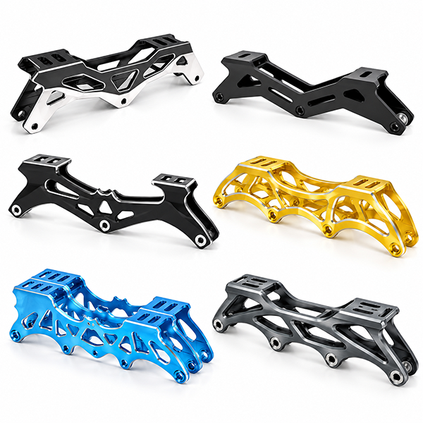
Explore representative inline speed skate frame structures supported through precision CNC machining for prototypes and end-use production. Wheel layout, frame length, wheelbase, mounting interface, lightweight architecture and cosmetic details can be customized to your engineering requirements. Customer-part images are shown only when authorized; representative images are provided for manufacturing reference.
Custom 4-wheel frames machined around your specified wheel diameter, wheelbase, axle locations, boot interface and weight-reduction geometry.
Request a Quote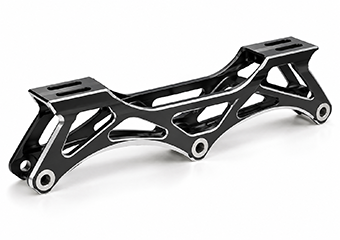
Large-wheel 3-wheel designs reviewed for axle position, wheel clearance, frame length, pocket depth and mounting relationships before machining.
Request a Quote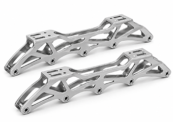
4×110-type layouts manufactured from customer drawings with controlled axle relationships, mounting geometry, threads, pockets, logos and finish requirements.
Request a Quote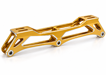
3×125 designs reviewed around large-wheel clearance, frame length, axle spacing, structural stiffness and the boot-to-frame mounting relationship.
Request a Quote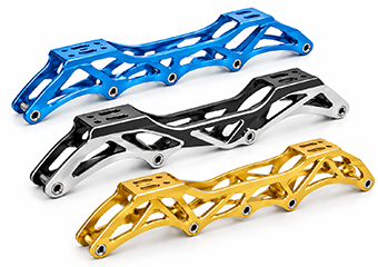
Special frames with alternate axle positions or multiple wheel layouts can be machined when geometry and functional relationships are defined in the CAD model.
Request a Quote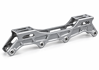
Deep pockets and ribs are reviewed for remaining wall thickness, cutter access, fixture support and distortion risk before final toolpaths are released.
Request a Quote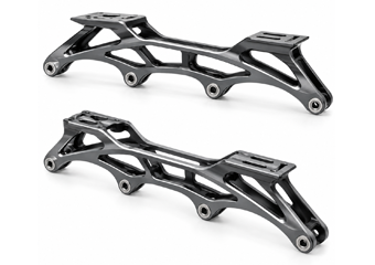
Common or non-standard mounting holes, slots, contact surfaces and spacing are machined from controlled datums according to your assembly requirements.
Request a Quote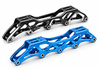
Send your STEP, 2D drawing or sample data for a non-standard frame developed around your wheel layout, material, mounting, branding and finishing requirements.
Upload Your DrawingA frame can look correct and still create wheel or boot-assembly problems. Process planning therefore focuses on the dimensional relationships that affect real fit, alignment and repeatability.
Multiple axle locations are planned from common datums so individual hole errors do not accumulate across the frame.
Mounting features are controlled as one functional interface rather than isolated dimensions.
Roughing, fixture support and finish-machining sequence are planned around long, pocketed aluminum structures.
Axle position, sidewalls, fasteners and wheel envelope are reviewed together where assembly data is available.
Weight reduction is balanced against tool access, wall stability, corner radii and fixture support.
Threads, axle interfaces and mounting surfaces are reviewed for allowance, masking or finish sequence where coating affects fit.
A geometry that works in CAD can still create unnecessary machining risk, difficult tool access, unstable thin walls, tolerance stack-up or finishing problems in production. VMT reviews the complete frame as a functional assembly so manufacturing risks can be identified before they become prototype failures, rework or repeat-production variation.
Problem: Wheel layout and axle stations can become inconsistent when each position is treated as an isolated feature.
VMT Control: Review wheel diameter, axle center distances, clearance envelope and the common datum relationship used for machining and inspection.
Target Result: More consistent wheel geometry with lower alignment and interference risk.
Problem: A long frame magnifies accumulated positional error and can move after heavy stock removal.
VMT Control: Review overall frame length, wheelbase, roughing balance, fixture support and when final length-related features should be finished.
Target Result: More stable overall geometry and repeatable wheel spacing after machining.
Problem: Mounting holes, slots and contact surfaces can stack error relative to the wheel axes and create assembly correction work.
VMT Control: Relate mounting spacing and contact surfaces to the functional datum chain, including common or custom mounting relationships defined by the drawing.
Target Result: More repeatable boot-to-frame assembly with better wheel-to-mount relationship.
Problem: Slot length, width, edge distance or position can limit adjustment range or weaken clamping areas.
VMT Control: Review slot geometry, cutter access, edge distance, clamping surface and positional tolerances before CAM programming.
Target Result: Usable adjustment range with secure mounting and fewer fit corrections.
Problem: Aggressive pockets can increase chatter, tool deflection and cycle time while removing support needed for later finishing.
VMT Control: Review pocket depth, rib geometry, internal radii, remaining material and fixture support before releasing toolpaths.
Target Result: Preserve the lightweight design intent while improving machining stability and repeatability.
Problem: Long thin walls can move as material stress is released, especially after deep roughing operations.
VMT Control: Review minimum remaining wall sections, roughing allowance, balanced material removal, clamping force and finish-machining sequence.
Target Result: Lower distortion risk and fewer correction cycles on the final frame.
Problem: Deep narrow cavities may require long-reach tools, increasing vibration, deflection and machining time.
VMT Control: Check cavity depth, tool reach, setup orientation, multi-axis access and whether local geometry can be made more tool-friendly without changing function.
Target Result: More stable cutting, better surface quality and a more efficient machining route.
Problem: Very small internal radii force smaller cutters and longer cycle times, even when the radius has no functional purpose.
VMT Control: Compare specified radii with practical cutter diameters and identify where a larger radius can be accepted after engineering review.
Target Result: Lower machining time and more robust toolpaths without changing critical frame function.
Problem: Axle bores, threads and fastening features can lose fit through tolerance stack-up, tool wear or coating buildup.
VMT Control: Review bore position, thread specification, engagement, gauge method, machining sequence and post-finish requirements.
Target Result: More reliable axle and fastener assembly with fewer post-process corrections.
Problem: Independent datums and unnecessary tight tolerances increase cost while allowing functional relationships to drift.
VMT Control: Separate axle, mounting and mating dimensions from non-functional cosmetic geometry and build machining/inspection around common functional references.
Target Result: Precision is concentrated where it controls assembly, with lower unnecessary machining and inspection cost.
Problem: Visible surfaces can pick up fixture marks, tool transitions or inconsistent polishing/blasting texture if cosmetic zones are defined too late.
VMT Control: Identify A-surfaces, allowable clamp areas, grain direction, polishing or blasting preparation and handling requirements before process planning.
Target Result: Better appearance consistency with less cosmetic rework after machining.
Problem: Anodizing can change axle holes, threads, slots and contact surfaces when allowance or masking is not planned.
VMT Control: Review critical finished dimensions, coating-sensitive areas, masking zones and whether inspection should occur before or after finishing.
Target Result: More reliable post-anodizing fit and fewer assembly problems on finished parts.
The purpose of DFM is not to redesign your product without approval. It is to identify manufacturing risks early, explain how those risks affect machining, finishing or inspection, and agree on practical options before they become prototype failures or repeat-production variation.
Inline speed skate frames should be validated as complete functional hardware before repeat production. The prototype stage gives your team a controlled opportunity to verify mounting, wheel clearance, axle relationships, structural geometry, finish and real assembly feedback.
Review material, wheel layout, frame length, mounting interface, tolerances, surface finish and the dimensions that control final assembly.
Identify thin walls, pocket depth, tool-access limits, datum risks, finish allowance and unnecessary tolerance cost before programming.
Machine first parts with the selected fixture and process route while keeping records that can support later revisions and production.
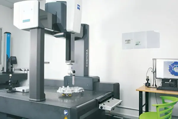
Check specified axle, mounting, thread, straightness and other functional dimensions using suitable gauges, 2D systems or CMM measurement.
Your team tests the frame with the intended boot, wheels, axles and hardware to confirm fit, clearance and functional relationships.
Update geometry, mounting features, weight-reduction details, tolerances or finish requirements based on prototype feedback before release.
Freeze the released drawing, approved process route and critical inspection points so repeat orders follow a controlled manufacturing baseline.
Material selection affects frame weight, stiffness, machining stability and finishing, so VMT reviews each option together with your geometry, wall thickness, pockets, axle features and application requirements. Aluminum alloys remain the primary choice for most complete CNC skate frames, while titanium and stainless steel are better suited to reinforced interfaces or related hardware, and carbon-fiber concepts require project-specific review of composite-to-metal structures.
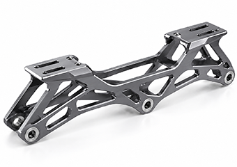
7075-T6 suits lightweight performance frames; high strength supports thin, pocketed structures, while bead-blast anodizing adds protection and gives brands a durable premium finish.
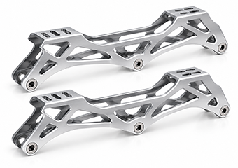
6061-T6 suits prototypes and production frames; reliable machinability and corrosion resistance support complex milling, while anodizing delivers consistent color with practical manufacturing cost.
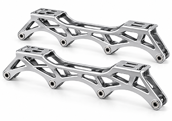
7050 aluminum suits high-load premium frames; high strength and fatigue resistance support rigid structures, while anodizing protects surfaces and supports long-term performance.
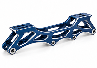
6082-T6 suits robust custom frame designs; good strength, machinability and corrosion resistance pair well with anodizing for durable, cost-controlled production.
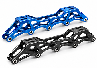
7000-series aluminum supports strength-critical frames; alloy choice balances stiffness, weight and machinability, with anodized finishes selected to meet appearance and durability targets.
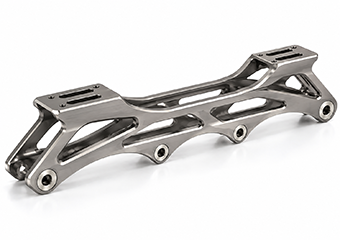
Grade 5 titanium suits premium interfaces or special frame components; high strength-to-weight and corrosion resistance support compact designs with durable blasted or polished finishes.
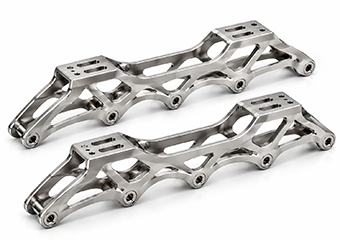
Stainless steel suits wear-critical inserts, axles or reinforced interfaces; strength and corrosion resistance support repeated assembly, with passivation or polishing improving long-term durability.
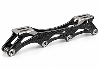
Carbon fiber suits hybrid ultra-light frame concepts; VMT reviews composite-to-metal interfaces and CNC-machined mating parts, helping designers reduce weight without compromising assembly accuracy.
The goal is not simply to remove material. A stable process must protect the relationship between axle features, mounting datums, long sidewalls and lightweight pockets while controlling distortion, setup variation and unnecessary machining cost.
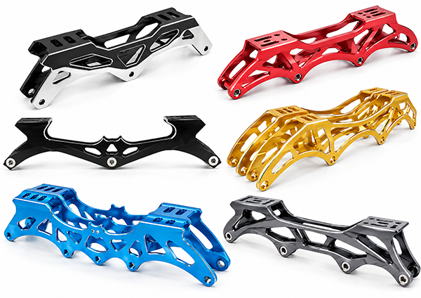
Problem: Removing deep pockets too early can release stress and leave thin walls unsupported.
Control: Stage roughing, retain temporary material where useful, then re-reference before finish machining.
Result: More stable critical geometry after major stock removal.
Problem: Excess clamping force can distort a long frame during machining, then spring back after release.
Control: Fixture from functional datums and support thin regions without overloading visible or critical surfaces.
Result: Lower risk of fixture-induced dimensional error.
Problem: Repeated setups can transfer error between axle holes, mounting surfaces and side features.
Control: Group related features around shared datums and reduce unnecessary re-clamping where geometry permits.
Result: Better positional consistency across the frame.
Problem: Final-size critical features can drift if machined before the structure has stabilized.
Control: Finish axle, mounting and other specified critical features after roughing and intermediate checks.
Result: More reliable final dimensions and assembly fit.
Problem: Angled faces, compound pockets or multi-side details may require several setups on simpler equipment.
Control: Use 3/4-axis or 5-axis machining according to actual geometry—not simply because the machine is available.
Result: Fewer setup transfers where they materially improve accuracy or efficiency.
Problem: Tool wear or process movement can affect a long production run before final inspection.
Control: VMT performs first-article and in-process checks; production quality reviews are carried out at defined intervals, including two-hour checks where applicable.
Result: Earlier detection, less accumulated rework and more stable repeat production.
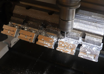
For repeat frame designs with a suitable constant section, extrusion can reduce raw-material waste and roughing time before CNC creates axle, mounting, pocket and cosmetic features.
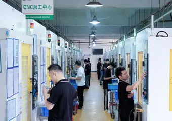
Well suited to most frame bodies, long pockets, axle features and indexed side machining where a cost-effective datum strategy can maintain the required relationships.
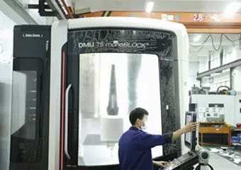
Applied when complex angled transitions, multi-face geometry or access constraints justify reducing setup transfers and maintaining related features in fewer operations.
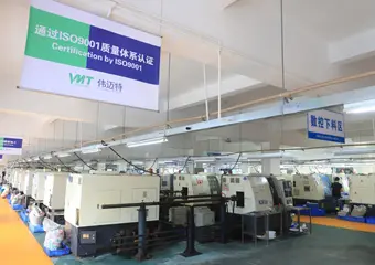
Used mainly for related axles, spacers, bushings or cylindrical inserts rather than the main frame body, supporting concentric and threaded interfaces within the assembly.
Surface finishing must protect the frame and deliver the intended brand appearance without changing axle, thread, mounting or contact features. VMT coordinates pre-finish preparation, anodizing allowance, masking, color requirements and post-finish inspection so cosmetic consistency and functional fit are controlled as one manufacturing requirement.
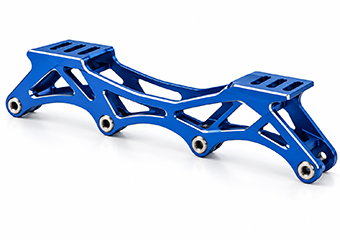
Aluminum speed frames use Type II anodizing for brand colors and corrosion protection, creating a uniform finish that improves appearance while supporting durable everyday use.
Discuss This Finish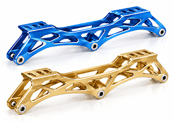
Premium aluminum frames are polished before anodizing to refine visible surfaces, producing brighter color and smoother appearance that strengthens high-end product presentation.
Discuss This Finish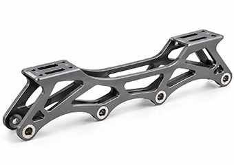
Aluminum speed skate frames use bead blasting before anodizing to create uniform matte texture, reducing visible machining variation and giving brands a consistent premium appearance.
Discuss This Finish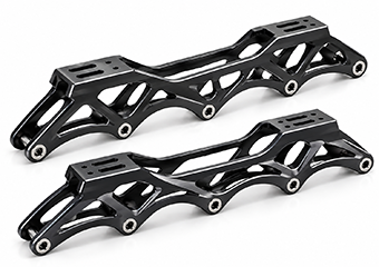
Wear-exposed aluminum frame surfaces use hard anodizing for higher surface hardness, improving abrasion resistance while helping customers extend service durability on demanding designs.
Discuss This Finish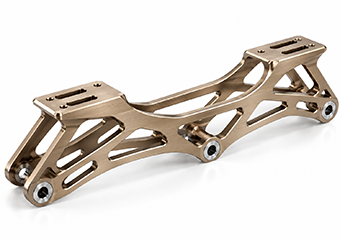
Visible aluminum frames use directional brushing before anodizing for controlled texture, creating a technical premium look that supports distinctive brand styling and surface consistency.
Discuss This Finish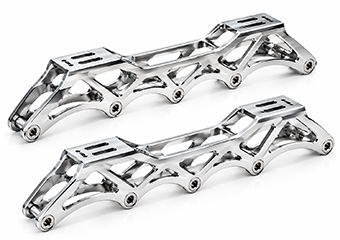
Appearance-focused frame surfaces use controlled polishing for high reflectivity, highlighting machining form and giving premium products a brighter, more visually distinctive finish.
Discuss This Finish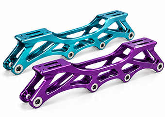
OEM aluminum frames use custom anodized colors for product differentiation, combining corrosion protection with controlled brand appearance and more consistent visual identity across batches.
Discuss This Finish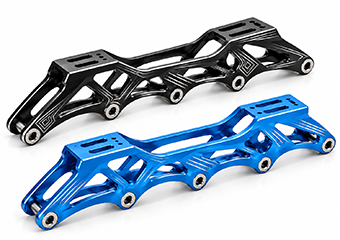
Finished skate frames use laser marking for logos, model data and traceability, creating permanent identification that supports branding, part control and easier production tracking.
Discuss This FinishInspection is planned around function. VMT combines first-article, in-process and final inspection with CMM, 2D measurement, gauges and visual checks; critical dimensions can be controlled to tight drawing requirements after engineering review rather than applying one tolerance to the whole frame.
Risk: small positional errors accumulate across multiple wheels.
Control: inspect critical axle coordinates from defined datums using CMM or suitable 2D measurement; critical features can be 100% inspected when specified.
Data: critical dimensions can be controlled as tight as ±0.005 mm after engineering review where geometry and process allow.
Result: reduced risk of wheel misalignment and inconsistent assembly.
Risk: incorrect spacing or slot position can prevent boot adjustment or force assembly.
Control: verify mounting positions, slot geometry and relationship to frame datums with coordinate or height-based measurement.
Result: more repeatable boot-to-frame fit across prototypes and batches.
Risk: a distorted contact surface can tilt the frame or create unstable seating.
Control: inspect flatness according to the released drawing after the frame is removed from the fixture and, when required, after finishing.
Result: more reliable contact between frame and boot mounting surfaces.
Risk: parallelism drift can change wheel-to-boot relationship even when individual dimensions appear acceptable.
Control: inspect related faces from a common datum and record specified GD&T relationships.
Result: better assembly consistency and reduced hidden geometric error.
Risk: long pocketed aluminum can move after roughing or unclamping.
Control: combine intermediate checks with staged roughing/finishing; VMT performs defined in-process inspections, including two-hour production checks where applicable.
Result: earlier detection of process drift before a complete batch is affected.
Risk: damaged or undersized threads create assembly failure even when external dimensions pass.
Control: use thread gauges and visual inspection for specified thread features, with 100% checking of critical threads when required.
Result: fewer axle-installation problems at customer assembly.
Risk: incorrect pocket depth changes weight, stiffness and local wall stability.
Control: verify first-article pocket dimensions and monitor process-critical areas during production with suitable gauges or coordinate measurement.
Result: more consistent lightweight geometry across the production run.
Risk: color variation, scratches or coating buildup can affect both appearance and fit.
Control: finished parts receive appearance inspection; film thickness testing can be provided where specified, and critical cosmetic/dimensional features can be 100% inspected.
Result: better batch appearance consistency and fewer post-finish assembly issues.
VMT supports custom frame projects for speed-skating brands, product developers and OEM programs where wheel geometry, mounting, lightweight structure, finish and repeat production matter.
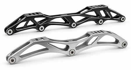
Custom frame geometry around application-specific wheel layouts, frame lengths, mounting relationships and weight targets.
Discuss This Application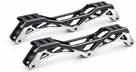
Projects prioritizing controlled wheel geometry, rigid mounting and lightweight construction according to the complete skate setup.
Discuss This Application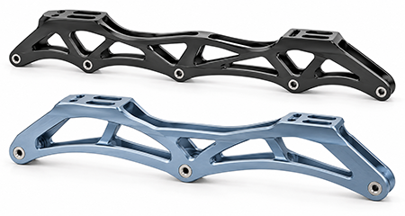
Frame designs balancing stiffness, wheel clearance, durability, mounting and surface protection for outdoor speed-skating programs.
Discuss This Application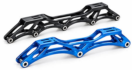
Long-distance projects balancing low mass, stable mounting, structural rigidity and wheel configuration around endurance-oriented product goals.
Discuss This Application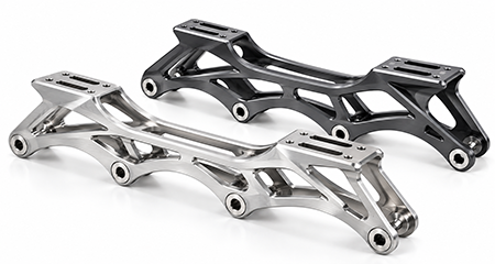
CNC prototypes used to validate custom mounting, wheel clearance, lightweight structure and finish before the design is released for production.
Discuss This Application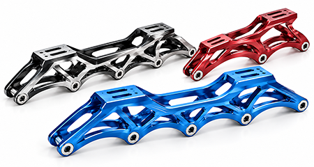
Customer-specific geometry, anodized colors, laser marking, inspection requirements and packaging coordinated after engineering review.
Discuss This Application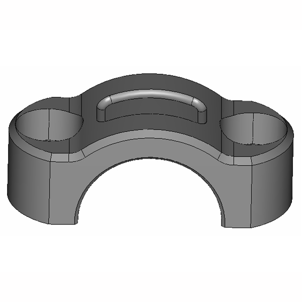
This 6061-T6 production case shows how VMT combined aluminum extrusion with CNC machining to control bearing-related assembly features, visible surfaces and repeatability across a 2,500-piece order. By planning the starting profile, datum strategy and fixturing around the functional interfaces, the process reduced unnecessary stock removal while supporting stable assembly and efficient repeat production.
An Italian motorcycle-component customer required a 6061-T6 upper cover with a visible curved profile and bearing-related functional assembly. The order quantity was 2,500 pieces, so the process needed to balance appearance, assembly accuracy and production economics rather than simply machine the entire geometry from solid billet.
The bearing connection could not be misaligned, while the long profile and cosmetic surfaces still needed stable machining. A poorly selected starting stock or fixture route would increase material removal, cycle time and the risk of positional variation during repeat production.
After reviewing the customer’s 3D drawing, VMT selected an extrusion + CNC route and planned auxiliary process holes, interchangeable process seats and the machining tail before production. Functional references were established first so machining and fixturing could support the bearing-related interface while reducing avoidable stock removal.
The approved route met the required assembly relationship and planned delivery while reducing unnecessary machining cost compared with a less efficient all-billet approach. The same decision logic is relevant to repeat skate-frame programs: define the functional datum chain first, then select stock form, fixtures, machining sequence and inspection around the released geometry.
Moving from one successful sample to repeat production requires a controlled baseline. The goal is to preserve the approved geometry, fixture references, machining sequence, finishing standard and inspection method while managing revisions deliberately.
Review geometry, material, functional interfaces, tolerances, surface finish, cosmetic zones and inspection requirements before the first prototype is released.
Manufacture first parts with the selected fixture, datum strategy and process route, recording critical setup information for later comparison.
The customer validates boot mounting, wheel clearance, axle fit, frame geometry and appearance using the actual mating hardware and intended application.
Any change to mounting features, pockets, weight, material, tolerance or finish is tied to the latest released drawing before the next manufacturing stage.
Confirm the released revision, critical inspection points, fixture references, finishing requirement and packaging method before repeat production expands.
Subsequent orders follow the approved baseline, with first-article, in-process and final inspection used to monitor the features that matter to assembly and appearance.
The feedback below reflects the outcomes customers value after delivery: parts that meet quality expectations, samples that pass validation, smooth transition into batch production and confidence to place repeat orders. These comments show the manufacturing reliability and project support VMT aims to deliver across custom CNC programs.

A complete RFQ helps engineering separate functional requirements from cosmetic preferences and select the right material, machining route, finishing process and inspection method.
Answers focus on engineering, sourcing, finishing and repeat-production issues that typically affect custom frame projects.
A: There is no universal winner. 6061-T6 usually offers easier machining, strong anodizing performance and practical cost for prototypes or many production frames. 7075-T6 provides higher strength for designs pushing thinner walls or higher stiffness-to-weight targets, but material and machining costs are higher. VMT reviews alloy choice together with wall thickness, pocket depth, frame geometry, finishing and target quantity instead of selecting material from strength alone.
A: We first identify the functional datum chain between axle locations and the boot mounting interface. Related holes are then planned around common machining references where geometry permits, rather than treated as unrelated dimensions. First-article and critical-feature inspection can use CMM or 2D measurement, and critical dimensions can be controlled to tight drawing requirements after engineering review. This approach reduces cumulative positional error across multiple wheel stations.
A: Yes. Long aluminum frames can move as deep pockets release internal stress and reduce structural support. VMT reviews roughing allowance, pocket sequence, temporary support, clamping force, remaining wall thickness and the timing of final machining. Intermediate checks can be added before critical features are finished. The objective is not to eliminate all material movement, but to manage it early enough that the final datum relationships remain within the released drawing.
A: Critical finished features should be identified before machining begins. VMT reviews whether each area should include machining allowance, masking, controlled coating, or inspection after finishing. Threads, axle interfaces and boot-contact surfaces are especially important because coating buildup can change fit even when the pre-finish dimension is correct. Our surface-finishing coordination and final inspection therefore treat appearance and assembly as one connected requirement.
A: A physical sample can help define shape and interface relationships, but it does not communicate the original tolerance intent, alloy condition, finishing allowance or acceptable wear. For stable repeat production, VMT recommends converting the sample into controlled 3D/2D manufacturing data and confirming critical dimensions with the customer. We can then build the machining and inspection plan around an approved drawing instead of reproducing unknown variation from the sample.
A: Yes, provided finishing is planned before release. Anodized color, bead blasting, polishing, brushing and laser marking can be coordinated with the drawing’s cosmetic zones and functional interfaces. VMT’s finishing process includes appearance inspection, while critical holes, threads and mounting areas can be masked or controlled according to project needs. This helps brands add a distinctive visual identity without treating finishing as an afterthought.
A: Cost reduction should start with DFM, not by simply removing more material. VMT reviews billet size, pocket depth, internal radii, number of setups, unnecessary tight tolerances and whether a repeat program could use extrusion plus CNC. We then separate strength-critical geometry from features that mainly increase machining time. The customer keeps design authority, while the manufacturing route is adjusted only after engineering agreement.
A: Billet is often the most flexible choice for early prototypes because there is no extrusion tooling commitment. For repeat production, a frame with a suitable constant cross-section may benefit from extrusion because less material must be removed by CNC. The decision depends on geometry, annual quantity, extrusion tooling, alloy availability, tolerance, surface requirements and design maturity. VMT can compare the two routes after reviewing the released frame model.
A: Appearance consistency starts before anodizing. Material lot, machining marks, polishing or bead-blast preparation, cleaning, rack contact and finishing parameters all influence the result. VMT coordinates machining and finishing requirements, uses defined cosmetic zones, and performs final appearance inspection after surface treatment. For brand-sensitive projects, color samples or approved reference parts should be established before larger production runs.
A: The issue should be corrected before production is released. VMT reviews the customer’s test feedback against the current revision, identifies which geometry or manufacturing feature must change, and updates the DFM/process plan after a new drawing is approved. This controlled revision step is important because changing a mounting slot, pocket or wall thickness can affect fixtures, toolpaths, finishing and inspection—not only the visible CAD geometry.
This guide is written for engineers, product developers and sourcing teams preparing a custom inline speed skate frame for prototype or OEM production. It focuses on decisions that influence fit, machining stability, finishing, inspection and production cost.
An inline speed skate frame should be dimensioned around the relationships that affect the final assembly, not simply around whichever surfaces are easiest to measure. The most important chain normally connects the boot mounting interface, axle locations, wheel clearances and any contact surfaces that determine how the frame sits under the boot. When those features are referenced independently, small coordinate errors can accumulate over the length of the frame even if every individual dimension appears acceptable.
Before requesting a quote, identify which surfaces establish the frame on the boot and which dimensions control wheel position relative to those surfaces. Use datums and GD&T where the relationship matters, and separate functional tolerances from cosmetic geometry. VMT uses this information to plan fixture references, machining sequence and inspection method. Critical dimensions can be controlled to tight requirements after engineering review, but applying the same tight tolerance everywhere normally adds machining and inspection cost without improving the product.
The practical result is a manufacturing plan built around the features that actually control wheel alignment and boot assembly, rather than around the easiest surfaces for the CNC operator to pick up.
6061-T6, 6082-T6, 7050 and 7075-T6 should not be compared by strength alone. The correct material depends on the frame’s wall thickness, pocket depth, structural ribs, mounting design, target mass, finishing specification and expected production quantity. A stronger alloy may allow a different geometry, but it may also increase raw-material cost and change cutting behavior. Conversely, a more economical alloy can perform well when the structure carries load efficiently.
For early prototypes, material selection should also consider availability and whether the prototype must accurately represent the final anodized appearance. If the production plan may later use extrusion, confirm that the target alloy and profile are commercially practical before freezing the geometry. The best material decision therefore connects mechanical performance, manufacturability, surface finish and supply-chain reality.
Weight-reduction pockets are visually attractive and can lower mass, but they also remove the material that supports the frame during machining. Very deep pockets, narrow ribs and long unsupported sidewalls increase tool reach, vibration and distortion risk. If the frame is aggressively pocketed before the critical axle and mounting features are finished, the part can move enough to complicate later precision machining.
A better DFM approach evaluates pocket depth, remaining wall thickness, internal corner radius, cutter access and fixture support as one system. Some areas may benefit from slightly larger radii or more material left near functional interfaces. These changes can shorten cycle time and improve stability without meaningfully increasing finished weight. The goal is not simply the lightest CAD model; it is a lightweight structure that can be produced repeatedly.
Wheel configuration affects more than the number of axle holes. Changing from a 4-wheel to a 3-wheel layout can alter frame length, wheelbase, clearance, pocket geometry and how material is distributed around the mounting platform. The boot interface must remain related to these axle positions so the frame behaves as intended when assembled.
For common 165 mm or 195 mm mounting references—or any custom interface—define hole or slot geometry, contact surfaces, adjustment range and datum relationships on the drawing. If a frame supports multiple wheel arrangements, identify which positions are primary and which are alternate. This allows manufacturing and inspection to prioritize the features that most directly control the intended setup.
Anodizing changes the finished surface condition. Even when coating growth is small, it can matter on axle holes, threads, precision slots and boot contact features. Cosmetic preparation also affects dimensions indirectly: polishing removes material, bead blasting changes texture, and masking can create transition edges. These steps should therefore be included in the manufacturing plan rather than added only after machining is complete.
Define cosmetic surfaces, color requirements and functional areas on the drawing. Where a critical fit must remain stable after anodizing, discuss whether the dimension is controlled before or after finishing and whether masking is required. A coordinated machining-and-finishing plan reduces the chance that a visually excellent part becomes difficult to assemble.
A feature is only useful as a production requirement if it can be measured reliably. Critical axle coordinates, mounting positions, flatness and parallelism should be dimensioned from accessible datums. If a tolerance can only be checked with an elaborate setup that is unrelated to functional assembly, inspection becomes slower and more expensive.
VMT combines first-article, in-process and final inspection according to the released drawing. CMM, 2D systems, height gauges, thread gauges and visual inspection are selected based on feature type. Critical dimensions can be 100% inspected when the project requires it, while less critical features may follow an agreed sampling plan. Building inspection logic into the drawing helps the approved prototype become a repeatable production baseline instead of a one-off successful part.
Send your STEP file and drawing to review frame geometry, material, axle and mounting relationships, machining risks, finishing and inspection requirements before manufacturing begins.
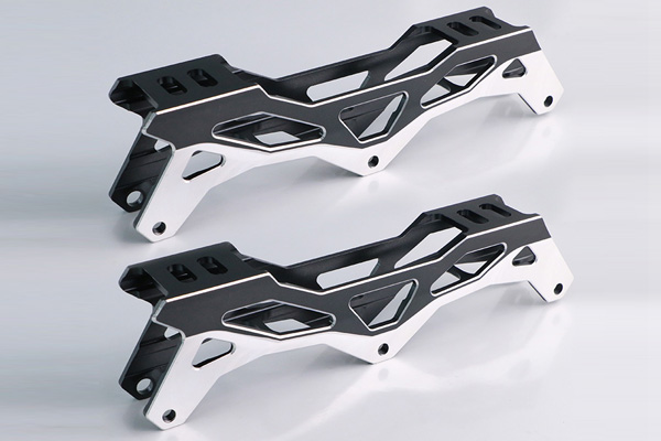
 Related suggestion
Give us a call or send an inquiry to our emailbox, we will answer your doubts according to your customers' requirements, and quote you immediately.


 +86 15099911516