16 years one-stop China custom CNC machining parts factory

Hey there I’m VMT Sam!
With 25 years of CNC machining experience we are committed to helping clients overcome 10000 complex part-processing challenges all to contribute to a better life through intelligent manufacturing. Contact us now
 0 |
Published by VMT at Aug 13 2026 | Reading Time:About 6 minutes
0 |
Published by VMT at Aug 13 2026 | Reading Time:About 6 minutes


Aluminum Deep Drawing Process: How to Manufacture Precision Aluminum Enclosures
A deep-drawn aluminum housing may look simple, but cracking, wrinkles, uneven wall thickness, springback, scratches, and dimensional variation can quickly create production problems. Even after forming, inaccurate holes, thin-wall deformation, or poor datum control can cause assembly failures. Successful production requires you to coordinate material selection, forming, CNC machining, finishing, and inspection.
Aluminum deep drawing is a metal-forming process that uses a punch, die, and blank holder to transform flat aluminum sheet into a cup, shell, housing, or enclosure. After forming, CNC machining can add precision holes, threads, slots, sealing surfaces, and assembly features that are difficult to control during the drawing operation alone.
If your aluminum enclosure requires both a thin formed body and precision assembly features, understanding the relationship between deep drawing and secondary CNC machining can help you reduce deformation, scrap, rework, and production risk.
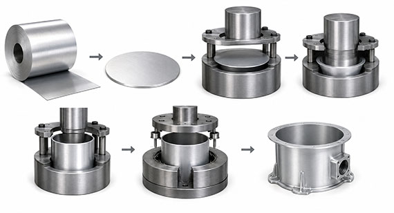
Aluminum deep drawing is a sheet metal forming process in which a flat aluminum blank is forced into a die cavity by a punch. As the punch moves downward, material flows from the flange area into the die and gradually forms a three-dimensional component.
The process normally involves four basic elements:
a blank holder that controls material flow.
Unlike CNC machining, deep drawing does not create a housing by cutting away large amounts of material. Instead, it redistributes the existing sheet metal into the required shape.
The basic manufacturing idea is:
Flat Aluminum Sheet → Formed Near-Net-Shape Housing
This makes deep drawing especially useful for thin-wall aluminum components where producing the entire body from solid billet would require substantial material removal.
However, forming the basic shell is only part of the manufacturing process. If your finished enclosure requires accurate mounting holes, threads, connector openings, sealing surfaces, or precisely controlled assembly interfaces, secondary CNC machining is often required.
What Types of Aluminum Parts Can Be Deep Drawn?
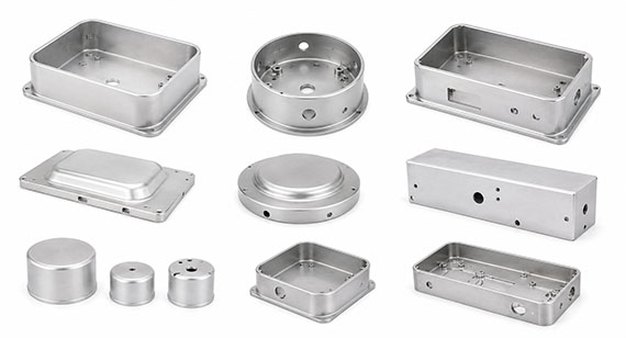
Aluminum deep drawing can be used for many parts with relatively continuous thin-wall geometry, including:
camera and optical equipment shells.
The suitability of deep drawing depends on more than the general shape. Material grade, temper, sheet thickness, drawing depth, corner radii, wall geometry, tooling, and production quantity all affect whether the process is practical.
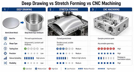
The term “aluminum stretching” can cause confusion because deep drawing and stretch forming are different processes.
For most cup-shaped, cylindrical, or enclosure-type aluminum shells, deep drawing is usually the more accurate manufacturing term.
| Process | How It Works | Best Suited For | Precision Features |
| Deep Drawing | A punch draws flat sheet into a die | Cups, shells, housings, enclosures | Usually requires secondary machining |
| Stretch Forming | Sheet or profile is held in tension and formed over a die | Large curved panels and skins | Limited |
| CNC Machining | Cutting tools remove material | Precision parts and functional features | Excellent |
Deep Drawing
Deep drawing is commonly used when you need a thin-wall three-dimensional enclosure.
Typical geometries include:
container-like parts.
Its primary purpose is to produce the overall shape efficiently.
Stretch Forming
Stretch forming holds a sheet or profile under tensile force while it is pulled around a form.
It is better suited to large-radius curved components such as:
large curved covers.
It should not be treated as another name for conventional deep drawing.
CNC Machining
CNC machining becomes valuable when the formed enclosure needs features that require tighter positional or dimensional control.
Typical features include:
precision bores.
The simplest way to understand the relationship is:
Deep drawing creates the housing geometry. CNC machining creates the precision required for final assembly.
Choosing the correct aluminum alloy is one of the first decisions in a deep drawing project.
The strongest aluminum is not automatically the best choice. You need to consider formability, final mechanical performance, corrosion resistance, machining requirements, cosmetic finish, and production method together.
1100 Aluminum
1100 aluminum provides very good formability and is suitable for parts requiring significant material deformation.
Its advantages include:
good surface finishing potential.
Its main limitation is relatively low mechanical strength.
For simple deep shells where strength is not the primary requirement, 1100 can be a practical option.
3003 Aluminum
3003 aluminum provides a useful balance between formability and moderate strength.
It is commonly considered for:
non-structural enclosure components.
It also provides good corrosion resistance.
5052 Aluminum
5052 aluminum is useful when your enclosure requires greater strength while still maintaining good forming capability.
Typical advantages include:
good finishing characteristics.
For electronics, industrial, transportation, or outdoor applications, 5052 can provide a practical balance between forming and final mechanical performance.
6061 Aluminum
6061 aluminum deserves more careful consideration.
It is extremely common in CNC machining, but 6061-T6 should not automatically be treated as an ideal material for severe deep drawing.
The actual forming capability depends on:
required final mechanical properties.
If the final design requires 6061 properties, the forming condition and heat-treatment sequence may need to be considered as part of the manufacturing plan.
Aluminum Alloy Comparison
| Aluminum Alloy | Formability | Strength | Corrosion Resistance | CNC Machinability | Typical Use |
| 1100 | Excellent | Low | Good | Good | Deep simple shells and covers |
| 3003 | Very Good | Low-Medium | Good | Good | General formed housings |
| 5052 | Good | Medium | Excellent | Good | Stronger corrosion-resistant enclosures |
| 6061 | Temper-dependent | Medium-High | Good | Excellent | Parts requiring significant secondary CNC machining |
Tip: Select the material based on both the forming process and the final part requirements. Choosing an alloy only because it has higher strength may increase cracking, tooling, or process-control problems.
For other aluminum and engineering materials, you can also review VMT's CNC machining materials options.
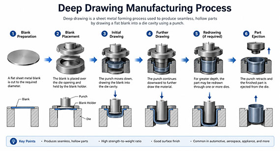
A finished deep-drawn aluminum enclosure normally requires more than one forming operation.
A typical production route is:
Material Selection → Blanking → Lubrication → First Drawing → Redrawing if Required → Trimming → Heat Treatment if Required → CNC Machining → Deburring → Surface Finishing → Inspection
Each step can affect the final part.
Step 1: Aluminum Sheet and Blank Preparation
Deep drawing begins with the correct sheet material.
Before forming, manufacturers need to consider:
cosmetic surface requirements.
Blank geometry is especially important because the blank must provide enough material to form the walls without creating excessive flange material or unnecessary trimming.
The raw material also needs to be consistent from one production batch to another.
Step 2: Lubrication
Lubrication reduces friction between the aluminum sheet and the punch, die, and blank holder.
Poor lubrication can increase the risk of:
premature tooling wear.
For cosmetic aluminum housings, lubrication also affects surface quality. A part may meet dimensional requirements but still become unusable if forming marks remain visible after anodizing or polishing.
Step 3: First Deep Drawing Operation
During the first draw, the punch pushes the blank into the die while the blank holder controls how material flows inward.
Blank-holder control is important.
If material flows too freely, wrinkles may form.
If material flow is restricted excessively, local strain can increase and the part may crack or tear.
The forming process therefore needs to balance:
Holding Force + Material Flow + Tool Geometry + Lubrication + Material Formability
rather than relying only on greater press force.
Step 4: Redrawing for Deeper Aluminum Housings
A deep aluminum shell cannot always be produced safely in one operation.
Depending on the relationship between diameter, width, depth, corner radius, and material condition, the enclosure may require:
First Draw → Redraw → Additional Draw → Final Forming
Multiple forming stages distribute deformation more gradually.
This can help control:
dimensional instability.
Trying to achieve excessive depth in one operation can create more scrap than using a properly planned multi-stage forming process.
Step 5: Trimming and Edge Control
After drawing, the upper edge may not have the final required height or shape.
The part can therefore require trimming to control:
burrs.
This operation is particularly important when the rim later interfaces with another housing, cover, gasket, or assembly component.
Step 6: Secondary CNC Machining
The deep drawing process creates the basic enclosure, but many functional features are better produced afterward.
CNC machining may be used to produce:
final trimming features.
This combination allows deep drawing to produce the thin-wall body efficiently while CNC machining focuses only on features that require higher precision.
A part may look suitable for deep drawing in a CAD model but become difficult to manufacture once actual material behavior is considered.
Important factors include:
number of forming stages.
Corner Radius
Small internal and external forming radii concentrate strain.
If a radius is too small relative to material thickness and drawing depth, it can increase the risk of:
inconsistent corner geometry.
If a functional design allows a larger radius, the forming process can often become more stable.
Drawing Depth
A deeper enclosure generally requires greater material movement.
This does not mean the correct solution is simply to use more forming force.
A deep housing may require:
intermediate heat treatment where appropriate.
DFM review should determine the forming route before production tooling is finalized.
Wall Thickness
Sheet thickness affects both forming and later CNC machining.
If the wall becomes too thin, the housing may be more vulnerable to:
assembly instability.
At the same time, unnecessarily thick material increases forming force, part weight, and material cost.
Complex Geometry
Symmetrical round shells are generally easier to control than housings containing:
irregular flanges.
Complexity should therefore be considered during the earliest design stage.
DFM Tip: Do not force precision holes, threads, or tight-tolerance assembly features into the drawing operation when they can be produced more reliably through secondary CNC machining.
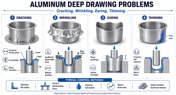
Deep drawing defects are not only cosmetic problems. They can affect CNC setup, assembly accuracy, surface finishing, and batch consistency.
1. Cracking or Tearing
Cracking usually occurs where local material strain exceeds what the sheet can accommodate.
Possible causes include:
aggressive one-stage forming.
The solution may require changes to material, tooling, blank geometry, forming sequence, or lubrication rather than simply increasing press capacity.
2. Wrinkling
Wrinkling often develops when excessive material flows into an area without sufficient control.
It may be influenced by:
material thickness.
Wrinkles can make later CNC clamping difficult and can remain visible on finished cosmetic surfaces.
3. Uneven Wall Thickness
Deep drawing redistributes material.
Some regions can experience greater thinning than others, particularly around highly strained geometry.
Uneven wall thickness can affect:
surface quality.
For precision housings, wall thickness should therefore be evaluated as part of both the forming and machining plan.
4. Earing
Earing appears as uneven peaks around the rim of a drawn part.
It is influenced by the directional properties of rolled sheet material.
Although the upper edge can normally be trimmed later, excessive earing creates:
process variation.
Material selection and blank orientation can therefore affect final production efficiency.
5. Springback
After forming pressure is released, the aluminum does not always remain exactly in the shape produced inside the tool.
Elastic recovery can slightly change the geometry.
This can affect:
later CNC locating.
The important point for a precision enclosure is that a formed surface is not automatically a precision machining datum.
6. Surface Scratches
Deep-drawn aluminum can be damaged by:
part-to-part contact.
These scratches are especially important when the final housing requires:
brushing.
Surface finishing cannot always hide defects created earlier in the manufacturing process.
7. Dimensional Variation
Formed dimensions may vary because of:
trimming operations.
Critical assembly dimensions should therefore be separated into:
forming-controlled features and CNC-controlled precision features.
This avoids forcing unnecessarily tight tolerances onto every deep-drawn surface.
8. Deformation After CNC Machining
A housing can pass deep-drawing inspection and still fail after secondary machining.
Typical causes include:
removal of material near flexible regions.
This is one of the main reasons deep drawing and CNC machining should be planned as one manufacturing process.
Cracking is one of the most expensive deep-drawing defects because it usually means the formed shell cannot be repaired.
The first step is identifying the actual cause.
Several manufacturing controls can help.
Choose a Suitable Aluminum Alloy and Temper
High strength does not always mean high formability.
The alloy must be compatible with the required deformation.
Increase Forming Radii Where the Design Allows
Extremely small radii concentrate strain.
A small DFM change can sometimes reduce forming risk without affecting the final assembly.
Use Multiple Drawing Stages
A very deep enclosure may be more stable when deformation is distributed over several operations.
Optimize Lubrication
Lubrication helps material flow more uniformly and reduces local friction.
Control the Blank Holder
Insufficient holding can create wrinkles.
Excessive restriction can increase cracking risk.
Maintain Tool Surfaces
Tool damage or contamination can increase friction and produce both cracks and cosmetic defects.
Use Intermediate Process Adjustment When Necessary
For difficult designs, material condition and forming sequence may need to be adjusted between stages.
Tip: A cracked aluminum housing is rarely only a “material problem.” Material, geometry, tooling, lubrication, and drawing sequence should be reviewed together.
These defects have different causes and should not be solved using the same corrective action.
| Defect | Typical Cause | Manufacturing Control |
| Wrinkling | Uncontrolled or excessive material flow | Optimize blank-holder force and blank geometry |
| Wall Thinning | Excessive local strain | Optimize radii and drawing stages |
| Earing | Directional sheet properties | Control material orientation and trimming allowance |
This is why a successful deep drawing process needs repeatable material, tooling, and forming parameters rather than only a visually acceptable first sample.
Deep drawing is excellent at creating thin-wall enclosure geometry.
It is not intended to replace CNC machining for every final feature.
A typical deep-drawn housing may still require CNC machining for:
final edge machining.
For example, a formed cylindrical housing may have sufficient overall roundness for the shell itself, while a mating bearing, seal, connector, or assembly feature requires much tighter accuracy.
Rather than trying to hold unnecessary forming tolerances over the complete part, VMT can use CNC machining to finish the features that actually control product function.
This approach can reduce manufacturing risk while keeping the thin-wall benefits of deep drawing.
You can learn more about VMT's custom CNC machining services for precision secondary machining.
Deep drawing is not automatically the best manufacturing process for every aluminum enclosure.
For early prototypes or low-volume designs that are still changing, machining directly from solid material can sometimes be more practical.
| Factor | Deep Drawing + CNC | CNC From Solid |
| Thin-Wall Geometry | Very suitable | Requires substantial material removal |
| Initial Tooling | Higher | Lower |
| Prototype Flexibility | Lower | High |
| Design Changes | More difficult after tooling | Easier |
| Material Waste | Lower for suitable shapes | Higher |
| Repeat Production | Strong advantage after validation | Depends on geometry |
| Precision Features | Added by secondary CNC | Directly machined |
| Production Efficiency | Good for stable repeat production | Strong for prototypes and lower volumes |
When CNC Machining From Solid May Be Better
Consider CNC machining first when:
forming-tool investment is difficult to justify.
When Deep Drawing + CNC Machining May Be Better
Consider a combined process when:
reducing material removal is important.
The correct decision should be based on total manufacturing cost and risk, not only the price of one individual process.
Secondary machining introduces a different set of challenges.
Thin-Wall Deformation
A thin shell can easily be distorted by fixture pressure.
A part may measure correctly while clamped and move after it is released.
Fixture support therefore needs to hold the housing without forcing it into an artificial shape.
Datum Instability
A formed surface may have enough variation that it cannot be used directly as a precision datum.
VMT reviews the relationship between:
Forming Datum → CNC Datum → Inspection Datum → Assembly Datum
This helps avoid machining a feature accurately relative to the wrong reference.
Hole Position Accuracy
Holes and connector openings often need to align with:
other enclosure halves.
If the formed housing varies slightly, fixture strategy becomes critical for maintaining the functional hole relationship.
Flatness
Flatness is particularly important on:
gasket interfaces.
If required flatness cannot be reliably created through forming alone, CNC finishing may be used on the critical interface.
Concentricity and Roundness
For cylindrical housings, roundness and concentricity may affect mating components.
Secondary machining can be used where critical bores or circular interfaces need tighter relationships than the formed shell.
Burr Control
Milling, drilling, tapping, and cutting openings can create burrs.
Poor burr control may cause:
coating defects.
Cosmetic Surface Protection
For appearance-sensitive enclosures, a dimensionally correct part can still be rejected because of scratches or clamp marks.
Fixtures, chip evacuation, handling, and packaging should therefore protect cosmetic surfaces throughout machining.
VMT approaches a deep-drawn aluminum housing as a complete manufacturing system rather than treating forming and CNC machining as unrelated operations.
DFM Review
Before production, our engineers review your 2D drawing and 3D model together with:
cosmetic areas.
The objective is to identify which geometry should be produced by deep drawing and which features should be reserved for precision machining.
Forming and CNC Datum Planning
One of the most common risks is allowing the forming datum and CNC datum to conflict.
VMT reviews how the enclosure:
finally fits into your assembly.
This prevents a part from meeting isolated dimensions while still creating assembly problems.
Fixture Optimization
Thin-wall components cannot always be clamped like solid aluminum blocks.
Depending on the geometry, fixture planning may require:
multiple location points.
The goal is repeatability without introducing deformation.
CNC Milling, Drilling, and Tapping
Secondary CNC operations can create:
sealing interfaces.
Machining parameters should also be matched to the stiffness of the formed enclosure.
Multi-Axis CNC Machining
When precision features exist on several sides, 4-axis or 5-axis CNC machining may help reduce repeated setups.
Fewer setups can simplify the relationship between multiple precision features and reduce accumulated positioning errors for suitable parts.
In-Process Inspection
Critical dimensions should be checked before the entire production batch is completed.
In-process inspection helps identify:
dimensional variation.
This allows corrections to be made earlier.
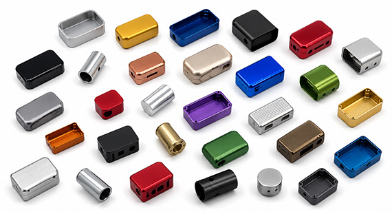
Surface finish is often a major purchasing requirement for aluminum enclosures.
The finishing process should therefore be considered during DFM—not after the enclosure has already been formed and machined.
Anodizing
Anodizing is commonly used to improve:
color options.
However, anodizing does not automatically hide forming defects.
Scratches, inconsistent surface preparation, deep tool marks, or handling damage can remain visible after finishing.
Bead Blasting + Anodizing
Bead blasting can create a more uniform matte texture before anodizing.
It is often suitable for electronics, audio equipment, camera products, and other appearance-sensitive housings.
The blasting process still needs to be controlled so that the texture remains consistent across production batches.
Brushing
Brushing provides a directional metallic texture.
If brushing is required, the direction and cosmetic surface should be defined on the drawing so that machining and handling do not interrupt the appearance.
Polishing
Polishing can be used for decorative metallic surfaces.
The raw deep-drawn surface needs good initial quality because severe forming marks are more difficult to remove consistently without affecting geometry.
Powder Coating
Powder coating provides:
different visual textures.
Coating thickness should be considered around assembly interfaces, threads, tight-fitting features, and grounding areas.
Laser Engraving
Laser engraving can add:
product markings.
It is generally completed after the surface condition and marking requirements are confirmed.
For more options, see VMT's surface finishing services.
Tip: If your enclosure contains a Class-A cosmetic surface, mark it on the drawing. This helps your supplier design tooling, CNC fixtures, inspection handling, and packaging around the appearance requirement.
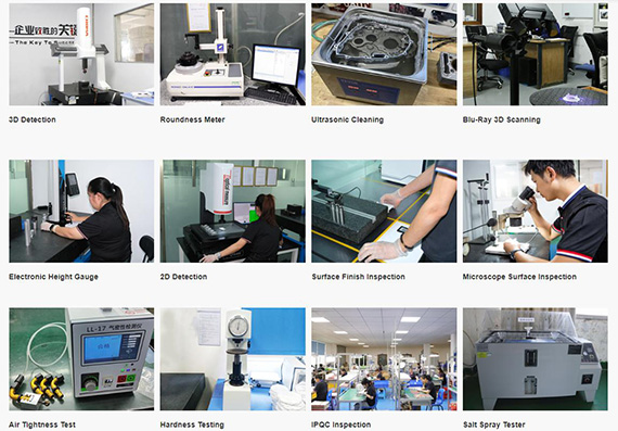
Deep-drawn components require inspection of both the formed geometry and the precision features added afterward.
Depending on the drawing, inspection may include:
cosmetic appearance.
Measurement equipment can include:
dedicated inspection fixtures.
First Article Inspection
The first article confirms whether the combined forming and CNC process can meet the drawing before repeat production begins.
Important characteristics may include:
assembly interfaces.
In-Process Inspection
In-process inspection helps detect changes before they affect an entire production batch.
Particularly important characteristics can be checked after critical machining operations.
Final Inspection
Final inspection should confirm more than isolated dimensions.
The finished housing may need evaluation for:
packaging condition.
For precision enclosures, functional relationships are often more important than one standalone dimension.
Deep drawing combined with CNC secondary machining can support many industries where thin walls and precision assembly features are both required.
Deep-drawn housings can reduce the amount of material required to produce electronic enclosures, while CNC machining adds ports, buttons, mounting holes, and internal locating features.
Medical and Laboratory Equipment
Instrument housings may require smooth external geometry together with precision sensor, display, or assembly interfaces.
Sensors and Instruments
Cylindrical or compact aluminum shells can be formed first and then machined for threads, connectors, sealing features, and mounting locations.
Deep drawing is suitable for many reflector, lamp, cover, and lighting enclosure geometries.
CNC secondary operations can then create mounting and electrical interfaces.
Electronic modules, sensors, lighting components, and other automotive enclosures can combine thin formed walls with machined functional features.
Industrial housings often require cable openings, mounting holes, covers, and durable surface finishes.
Microphone housings, control enclosures, and audio hardware may combine deep drawing with CNC machining and cosmetic anodizing.
Optical and imaging housings often require precise relationships between the enclosure and internal optical, sensor, or mounting components.
Battery and Power Electronics
Thin metal housings may need additional machining for connectors, fasteners, sealing, and thermal interfaces.
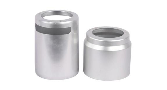
Project Background
A customer needs a thin-wall aluminum equipment housing with a deep-drawn body, side connector openings, several mounting holes, internal locating features, and a cosmetic anodized finish.
The basic housing geometry is suitable for forming, but several features need tighter positional control than the drawing process alone can provide.
Project Challenge
The main manufacturing risks include:
cosmetic scratching before anodizing.
Trying to control every feature directly through forming would make the tooling and tolerance requirements unnecessarily difficult.
VMT Solution
The manufacturing plan separates the requirements into two groups.
Deep Drawing Controls:
near-net-shape structure.
CNC Machining Controls:
critical interface dimensions.
A dedicated fixture supports the thin wall without excessive clamping. Critical features are machined relative to the functional datum structure, followed by deburring, dimensional inspection, surface finishing, and final appearance inspection.
Result
The prototype stage validates the forming allowance, CNC fixture, hole relationships, and surface-finish handling before repeat production.
This creates a more stable manufacturing route in which forming produces the enclosure efficiently while CNC machining is reserved for the dimensions that directly affect assembly and function.
A new aluminum enclosure should not move directly from CAD design into high-volume production without validation.
A lower-risk development route is:
Drawing Review → DFM Feedback → Material Confirmation → Prototype / Tooling Strategy → Deep Drawing Trial → CNC Machining → Dimensional Inspection → Assembly Validation → Surface Finish Sample → Batch Approval → Production → Final Inspection → Protective Packaging
Prototype Stage
During early development, your design may still change.
If only a small number of parts are required, CNC machining from solid material may sometimes provide a faster way to verify:
interface dimensions.
This can prevent premature investment in forming tooling.
Forming Validation
Once the design becomes stable, deep drawing samples can be used to validate:
appearance.
CNC Validation
The formed sample is then used to verify:
machined surfaces.
Surface Finish Validation
A finish sample is especially important for cosmetic aluminum products.
This confirms whether:
protected areas are handled correctly.
Batch Production
Only after the key risks are validated should the process be transferred into repeat production.
This approach reduces the chance that a design problem becomes a tooling or batch-production problem.
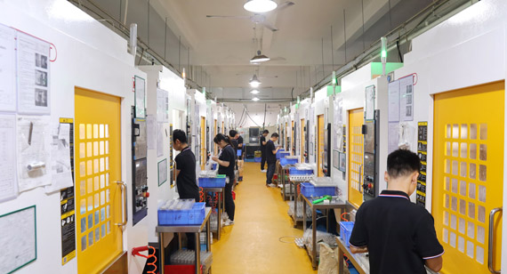
The best process depends on your project stage and commercial requirements.
CNC Machining From Solid May Be Better If:
most surfaces require precision machining.
Deep Drawing + CNC Machining May Be Better If:
reducing material removal is important.
Rather than asking only:
“Which process has the lowest part price?”
A better question is:
“Which process provides the lowest total manufacturing risk and cost for my project volume, geometry, tolerance, and design maturity?”
That decision should be made during DFM.
Deep drawing should not be treated as an isolated forming operation.
A reliable aluminum enclosure depends on the complete manufacturing chain:
Material Selection → Deep Drawing DFM → Tooling and Forming → CNC Secondary Machining → Deburring → Surface Finishing → Quality Inspection → Assembly-Ready Part
If the material is difficult to form, the housing may crack.
If material flow is poorly controlled, the shell may wrinkle or become too thin.
If the formed geometry is used incorrectly as a CNC datum, mounting holes and connector openings may shift.
If the fixture applies too much force, the thin wall may deform.
And if cosmetic requirements are considered only after machining, scratches or clamp marks can become expensive finishing defects.
VMT helps you evaluate these risks before production by connecting forming requirements with CNC machining, tolerances, surface finish, inspection, and final assembly.
Have a deep-drawn aluminum housing project? Upload your 2D drawing and 3D model. VMT can review your aluminum alloy, wall thickness, forming geometry, CNC features, tolerances, cosmetic surfaces, and inspection requirements, then provide DFM feedback and a custom manufacturing quotation.
Upload Your Drawings | Request a Quote | Get DFM Feedback
Send your 2D drawings, 3D CAD models, aluminum alloy, wall thickness, forming geometry, CNC features, tolerances, cosmetic surfaces and inspection requirements.
All information and uploaded files are secure and confidential.
1 Tell us what you need
2 Get DFM & quote
3 Approve production
Email: inquiry@vimetal.com.cn
Can Aluminum Be Deep Drawn?
Yes. Several aluminum alloys have good formability and can be used for deep-drawn housings, shells, cups, and covers. The correct alloy and temper depend on drawing depth, wall geometry, mechanical requirements, and subsequent machining.
What Aluminum Alloy Is Best for Deep Drawing?
There is no single best alloy for every project. 1100 provides excellent formability, 3003 provides a good general-purpose balance, and 5052 offers higher strength with good forming performance. Other alloys may be selected depending on final product requirements.
Can 6061 Aluminum Be Deep Drawn?
6061 can be formed under suitable conditions, but forming capability depends strongly on temper and geometry. 6061-T6 is considerably less suitable for severe deep drawing than softer material conditions, so the forming and heat-treatment sequence needs careful review.
What Causes Aluminum to Crack During Deep Drawing?
Common causes include excessive drawing severity, unsuitable material or temper, small corner radii, insufficient lubrication, poor material-flow control, and trying to achieve too much deformation in one operation.
How Do You Prevent Wrinkles in Deep-Drawn Aluminum?
Wrinkling can be controlled through suitable blank-holder force, blank geometry, material flow, tooling design, and sheet thickness. Increasing force blindly is not always the correct solution because too much restriction can contribute to tearing.
Does Deep Drawing Change Aluminum Wall Thickness?
Yes. Material flows and stretches during drawing, so wall thickness may not remain perfectly uniform throughout the part. Highly strained areas can become thinner and should be considered when strength or secondary CNC machining is critical.
Why Does a Deep-Drawn Housing Still Need CNC Machining?
Deep drawing creates the basic shell efficiently, but precision holes, threads, connector openings, sealing surfaces, locating features, and assembly datums often require tighter control. CNC machining is used to finish these functional features.
What Tolerances Can Be Achieved on Deep-Drawn Aluminum Parts?
There is no universal tolerance for every deep-drawn part. Formed-feature tolerance depends on size, geometry, material, thickness, tooling, and drawing depth. Critical features that require tighter tolerances can be completed through secondary CNC machining.
Can Deep-Drawn Aluminum Housings Be Anodized?
Yes. Deep-drawn aluminum housings can be anodized when the material and surface condition are suitable. Forming scratches, handling marks, and inconsistent surface preparation should be controlled before anodizing because they may remain visible afterward.
Is Deep Drawing Suitable for Prototypes?
It depends on the project. If the design is still changing and only a few units are needed, CNC machining can sometimes be more economical for prototype validation. Deep-drawing tooling becomes more attractive as the design stabilizes and repeat production is required.
How Are Thin-Wall Deep-Drawn Housings Inspected?
Inspection may include wall thickness, diameter, height, roundness, concentricity, flatness, hole position, threads, machined datums, and appearance. CMM, gauges, micrometers, and dedicated fixtures can be selected according to the drawing.
Can VMT Support Both Prototypes and Repeat Production?
Yes. VMT can review the drawing and determine whether CNC machining, deep drawing plus CNC secondary machining, or another manufacturing route is better suited to your design stage, geometry, tolerance, and expected production quantity.


 +86 15099911516




 Read more