16 years one-stop China custom CNC machining parts factory

Hey there I’m VMT Sam!
With 25 years of CNC machining experience we are committed to helping clients overcome 10000 complex part-processing challenges all to contribute to a better life through intelligent manufacturing. Contact us now
 370 |
Published by VMT at Oct 09 2026 | Reading Time:About 6 minutes


The journey from prototype design to CNC machining production in the realm of CNC machined parts manufacturing is a complex and intricate process. This article provides a detailed analysis of this process, aiding readers in comprehending how to efficiently and accurately realize the transition from concept to physical entity, while also addressing common challenges encountered along the way.
While initial prototyping focuses on validating functionality, scaling to volume production requires a strategic shift toward cost control and manufacturability. We will break down actionable DFM guidelines, smart tolerance and material choices, and essential procurement strategies that your team can implement to reduce cycle times and per-unit costs without compromising quality.
At the end, we will share a case study on a drone arm project, demonstrating how we combined DFM optimization with custom zero-point clamping and optimized CAM toolpaths to scale production to 2,000 units, helping clients cut manufacturing costs by 15% and shorten lead times by 20%.
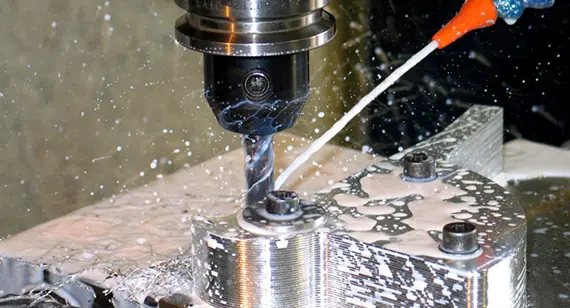
Prototyping is a pivotal stage in product development, allowing for the discovery and resolution of potential design issues before full-scale production.
Concept Prototype Design:
The concept prototype represents the initial idea of the product, focusing primarily on its overall layout and functional aspects. Designers use hand-drawn sketches or 3D modeling software to illustrate the general form and functionality of the product, providing direction for further design iterations.
Feature Prototype Design:
The feature prototype delves deeper into specific functionalities of the product. At this stage, designers concentrate on detailed design aspects such as structure, materials, and connection methods to ensure the realization of product functionality.
Evolutionary Prototyping:
Evolutionary prototyping involves iterative refinement of the product based on feedback from previous stages. Through multiple iterations, designers gradually enhance the design, improving product performance and user experience.
Effective time management is crucial during prototype creation to ensure smooth progress and ample preparation for subsequent production phases.
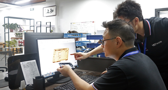
Following prototype design completion, market research and product testing are essential to understand market demands and feedback.
Transition to Small Batch Production:
Upon confirming the feasibility of the product design, it transitions from prototyping to small batch production. This phase aims to validate production processes and quality control measures in preparation for full-scale production.
Preparation of Design Blueprint Files:
Design blueprint files serve as crucial references for CNC machining production. When preparing these files, it is essential to ensure their accuracy and completeness to facilitate subsequent manufacturing processes.
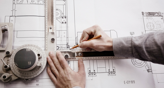
Design for Manufacturing (DFM) Analysis: Design Adjustments
DFM (Design for Manufacturing) analysis evaluates the manufacturability of product designs. Through DFM analysis, potential manufacturing issues are identified, allowing for adjustments to enhance manufacturability and production efficiency.
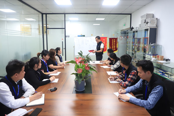
Quotation: Manufacturing Budget
Based on design blueprint files and DFM analysis results, the manufacturing budget for the product can be calculated, providing clients with accurate quotations.
CNC Machining Production
CNC machining production is a critical phase in realizing the transition from design to physical product. During this stage, appropriate CNC machining equipment and processes are selected to ensure product accuracy and quality.
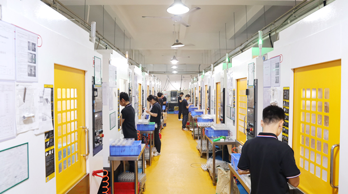
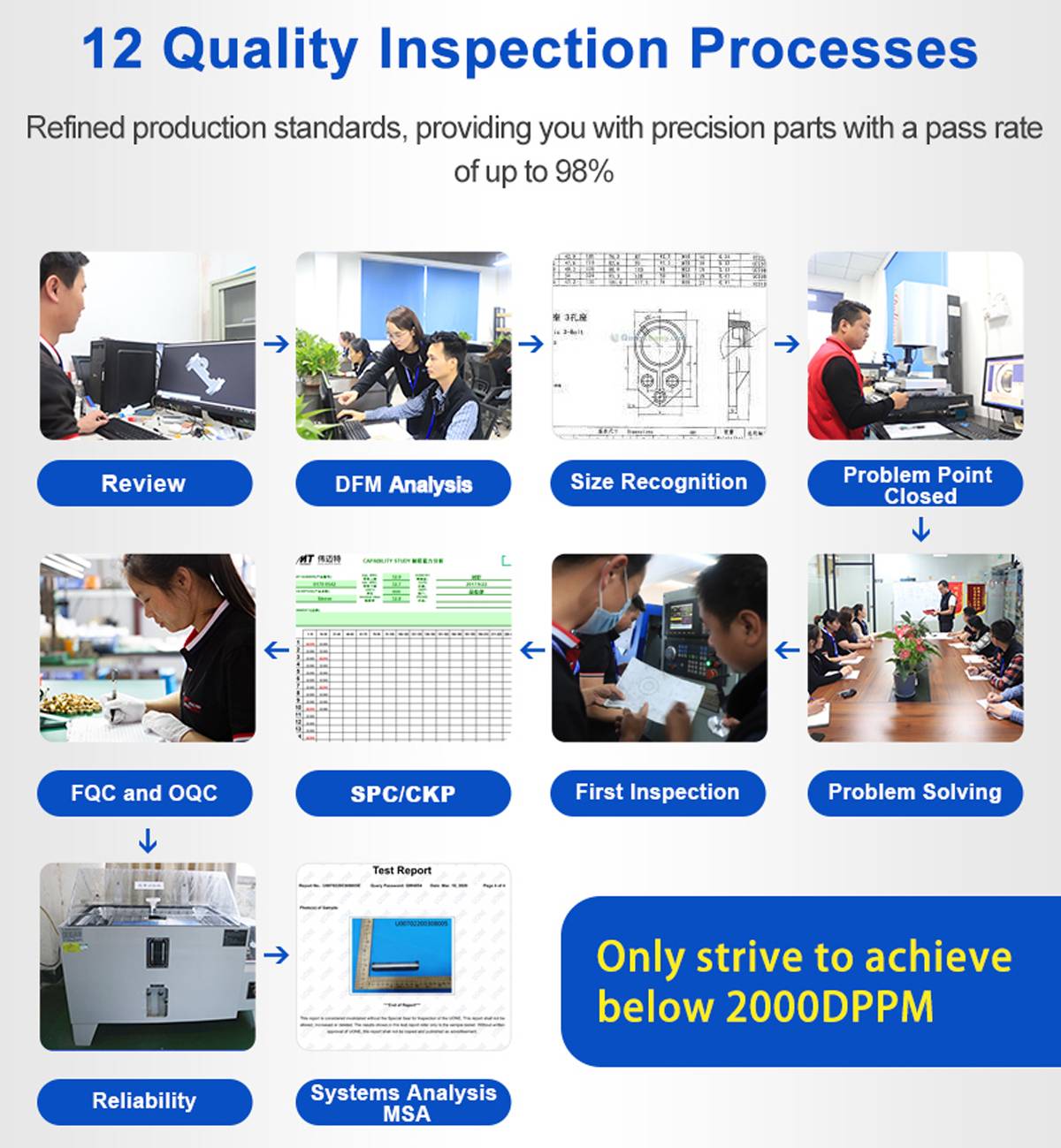
Quality Inspection: Reliability Testing
Quality inspection is essential to ensure product quality. Upon completion of CNC machining production, reliability testing is conducted to verify that the product meets design and market requirements.
Ideal Delivery Time
Reasonable delivery time is essential for meeting customer needs and enhancing customer satisfaction. Delivery time is planned based on production schedules and customer requirements to ensure timely product delivery.
Product Launch
Once products pass quality inspection and meet delivery requirements, they are officially launched and introduced to the market.
Transitioning a part from prototype to volume CNC production will need you make them efficiently, reliably, and cost-effectively.While it is not a big deal for producing a single prototype with custom setups and slow toolpaths, those unproper features can create lead time longer and budget wasting during mass manufacturing.
To prevent costly redesigns and delays later,you can implement these three critical DFM (Design for Manufacturability) optimizations right in the initial CAD model before ordering prototypes:
1. Try to Standardize and Oversize Internal Fillets
Design pitfalls:Prototype designs contain multiple unique internal corner radii (e.g., R1mm, R1.5mm, R2mm, R3mm) across different pockets and features.
Why this could be inappropriate: During prototyping, the machinist in your partner factory will simply swap tools manually or run extra passes, which is not a big deal. However, in volume production, frequent tool changes inflate cycle times and tool wear, and these increase the machining time , cost, and tool fees.
Optimization tips:
Standardize Radii: Consider to keep internal fillets uniform across the entire part (e.g., make all internal pocket corners a consistent R3mm). This minimizes tool changes and simplifies CAM programming.
Design for Tool Clearance (Avoid 90° Corner Engagement): Instead of using arbitrary decimal radii, design internal corners slightly larger than standard end mill radii. For example, if a feature naturally fits a standard 6mm end mill (R3mm), design the corner radius as R3.2mm or R3.5mm. This prevents the cutting tool from engaging the metal at a full 90-degree angle, allowing the machine to sweep smoothly through corners at higher feed rates, reducing machining time by 15% to 25% and avoiding tool chatter.
2. Cap Deep Pocket and Hole Aspect Ratios (The 4:1 Rule)
The Pitfall: Designing deep, narrow pockets or high-depth-to-diameter holes that go far down into the part.
Why this is inappropriate: A high depth-to-width ratio causes tool deflection, chatter, and high tool breakage rates, drastically increasing scrap rates and cycle times.
Optimization Tips:
Follow the 4:1 Depth-to-Diameter Rule: As a rule of thumb, keep pocket depths and hole feature depths under 4 times the feature's minimum width or cutter diameter (e.g., if a pocket is 6mm wide, limit its depth to 24mm).
Split Deep Cavities: If a deep feature is functionally necessary, consider splitting a complex deep part into two assembled components that can be easily machined separately and fastened together.
3. Standardize Thread Specs and Limit Blind Hole Depths
The Pitfall: Specifying custom non-metric/non-UNC thread sizes or designing excessively deep blind threaded holes.
Why this is inappropriate: Non-standard threads will make suppliers to order custom taps/thread mills, the time and fees will account in your order. Furthermore, threading a blind hole all the way to the bottom often leads to packed metal chips snapping taps inside the part during fast automated machining runs.
Optimization Tips:
Try to Use Standard Thread Sizes: Use standard metric or UNC thread callouts (e.g., M3, M4, M5, M6) available in your CAD library so suppliers can use off-the-shelf tooling.
Cap Thread Depth at 2–3x Diameter: Limit the functional thread engagement depth to 2 to 3 times the screw’s nominal diameter (e.g., maximum 12–18mm thread depth for an M6 bolt). Threads deeper than 2–3x diameter provide virtually no extra holding force but significantly increase the risk of broken taps in mass production.
Small, deliberate adjustments to your CAD files and drawing callouts can yield massive savings during volume production. The matrix below outlines other four practical design-level optimizations that directly streamline machine time and lower your unit costs:
|
Actionable Optimization |
How This Helps Reduce Cycle Time |
Benefits |
|
1. Relax Non-Critical Tolerances Avoid applying blanket tight tolerances (e.g., +/-0.01 mm) across the entire drawing. Relax aesthetic or non-mating surfaces to +/-0.1 mm or ISO 2768-m. |
Eliminates the need for slow, micro-finishing passes. The factory can use rough end mills with high material removal rates, drastically shortening machining time. |
Shorter machining time per part & lower unit cost. |
|
2. Reduce Machining Setups/Orientations Consolidate features onto 1-2 primary faces, avoiding holes or pockets spread across all six sides. |
Reduces the number of times a machinist must manually flip and re-clamp the part, minimizing machine downtime and operator intervention. |
Faster lead times, lower labor costs, and reduced cumulative positioning errors. |
|
3. Select Machine-Friendly Alloys When performance requirements allow, replace harder/gummier metals (e.g., use Aluminum 6061-T6 instead of 7075, or Stainless 304 instead of 316L). |
Increases cutting speeds by 30%-50% and extends tool life, allowing the CNC machine to cut faster and smoother. |
Faster production cycles and lower supplier quotes. |
|
4. Optimize Surface Finish Specs Avoid specifying Ra 0.4 um (mirror finish) across the whole part. Reserve Ra 0.8 um for critical sealing/sliding faces and Ra 1.6 um or 3.2 um for general surfaces. |
Prevents the CNC mill from spending hours making ultra-fine, slow passes with micro step-overs over non-critical surfaces. |
Prevents unnecessary machine time waste and cuts post-processing costs. |
Successfully scaling from CNC prototype parts to production requires more than just optimized CAD drawings, it demands a smart procurement strategy. Managing tiered order quantities and timing your supplier engagement correctly can prevent cost overruns, eliminate premature retooling, and ensure a seamless ramp-up.
1. Strategic Volume Planning: Leveraging Tiered Pricing (MOQ)
For CNC machining costs, setup fees, CAM programming, and custom fixturing are fixed costs. In prototyping (1–10 units), these costs are amortized over very few parts, leading to high unit prices. As volume increases, fixed costs are diluted, and per-unit prices drop significantly.
1–10 Units (Prototype Validation): Focus on function, fit, and assembly testing. Expect higher unit prices, but avoid ordering extra buffer units until design changes are locked in.
50–200 Units (Pilot Run / Bridge Production): This is the ideal stage for initial market testing or pilot builds. Asking suppliers for tiered pricing breaks (e.g., 50, 100, 200, 500 units) allows your team to find the "sweet spot" where setup overhead drops without overcommitting inventory capital.
500 to 5000 + Units (Mass Production): At this level, suppliers can justify specialized fixtures (like zero-point clamping or multi-station jigs) and bulk material purchases, yielding the lowest possible unit cost.
You can request a Tiered Quotation Table (e.g., quotes at 10, 50, 100, 500, and 1,000 units) during the initial RFQ. This gives your product teams clear visibility into unit cost drop-offs, helping you plan batch sizes and inventory buffers effectively.
2. When Should You Request a Formal DFM Review?
Timing is everything when engaging your CNC machining supplier for a DFM (Design for Manufacturability) review. Requesting it too early or too late can lead to wasted engineering time or redesigns.
Before Ordering Prototypes (Stage 1 DFM)
Before you place your prototype order, send your CAD files to the supplier for an initial DFM pass. Experienced CNC engineers can spot high-risk design features—such as deep pockets, non-standard threads, or tight internal corners—and suggest minor CAD tweaks before you pay for prototypes. This ensures your prototype is designed for scalable manufacturing from day one.
Before Pilot Run Release (Stage 2 DFM)
Once prototype testing is complete and functional modifications are finalized, perform a second DFM review before releasing the 50–200 unit pilot run. This is when you should discuss tolerance relaxation on non-mating faces, surface finish optimizations, and material spec adjustments with your supplier.
Why there are two DFM Stage?
Conducting a quick DFM before prototyping prevents obvious manufacturing flaws, while a final DFM before pilot production fine-tunes tolerances and fixtures for maximum cost savings, preventing premature optimization before your design is fully locked in.
But for the project falls under the following scenarios, completing a one-time DFM review is indeed feasible:
Simple or Mature Structures: Standard minor design updates or off-the-shelf structural components with extremely low validation risk.
Direct to Production: The prototype version is identical to the final mass-production version, with zero expectation of design changes or functional re-validation.
How we scale drone arm production from prototype to 2,000 units, helping clients cut manufacturing costs by 15% and shorten lead times by 20%.
A commercial drone client approached us to transition their custom aluminum alloy drone arm from prototype testing into a pilot production run of 2,000 units. The initial prototype design presented significant manufacturing hurdles: thin-walled geometry prone to heat deformation, overly deep internal pockets with tight R1.0mm corner radii, and a complex contour requiring machining across four different orientations. During initial small-batch attempts, these features led to long cycle times, tool chatter, and high scrap rates due to part warping.
Design for Manufacturability (DFM) Review
To address these manufacturing issues prior to volume production, our engineering team conducted a detailed DFM analysis and proposed several CAD modifications to the client. We suggested increasing the internal pocket corner radii from R1.0mm to R3.2mm, allowing the use of standard 6.0mm end mills to reduce tool wear and cycle times. We also proposed slightly increasing wall thickness in non-critical areas by 0.3mm to improve part stiffness during machining, along with relaxing non-mating tolerances to standard commercial grades. After the client reviewed and approved these design adjustments, the updated CAD files were released for production, effectively preventing part deformation and chatter without affecting the component's weight or fit.
Tooling, Fixturing, and CAM Toolpath Strategy
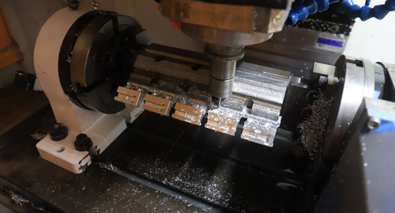
On the shop floor, we replaced traditional vise clamping with a custom-engineered multi-station fixture integrated with a zero-point clamping system. This setup allowed us to load and secure four drone arms simultaneously, reducing manual operator handling time by over 70% and eliminating positioning errors between setups. Concurrently, our CAM programmers optimized the machining strategy by implementing high-speed dynamic milling toolpaths with constant chip-load control, minimizing tool engagement angles and reducing total tool changes per part from eight down to three.
Results
By combining early DFM CAD optimizations with dedicated volume tooling and streamlined CAM programming, we successfully scaled the drone arm project to the target 2,000 units with consistent quality. The optimized cycle time allowed the client to save overall manufacturing costs by 15% and shorten total project delivery lead time by 20%.
The process from prototype to CNC machining production is a systematic endeavor that demands a high level of professionalism and precision at each stage. Through well-planned prototype design, market research, product testing, and production processes, we can ensure a smooth transition from concept to physical product and provide clients with high-quality CNC machining services.
Looking to lower per-unit costs and shorten lead times for your next production run? Contact our engineering team today to optimize your designs before ordering your next batch. [2D Drawings (PDF files), 3D Drawings (IGS/STP/STEP files)].
Send your drawings, requirements, and target quantity. VMT will review your project and provide a machining solution and quote.
All information and uploaded files are secure and confidential.
1 Tell us what you need
2 Get solution & quote
3 Approve production
Email: inquiry@vimetal.com.cn
Q1: What is the main difference between CNC prototyping and volume CNC production?
A: Prototyping focuses on fast design validation using temporary setups and slow, single-pass cutting paths. Volume production prioritizes unit-cost reduction and speed by using multi-station custom fixtures, optimized CAM toolpaths, and standardized CAD adjustments.
Q2: How can I modify my CAD design to reduce CNC machining costs without sacrificing functionality?
A: You can standardize internal corner radii to R3.2mm, cap pocket depths under a 4:1 width ratio, and consolidate features onto 1–2 faces. Additionally, relaxing non-mating tolerances to +/-0.1mm or ISO 2768-m eliminates slow finishing passes and significantly lowers cycle times.
Q3: When is the right time to request a DFM review from the supplier?
A: Request an initial DFM before ordering prototypes to catch major CAD flaws like tight corners or deep blind holes. Then, run a second DFM right before pilot production to fine-tune non-critical tolerances, surface finish callouts, and volume fixturing.
Q4: How do blanket tight tolerances on drawings affect CNC machining costs?
A: Applying tight tolerances (like +/-0.01mm) across the entire drawing forces the CNC mill to make slow micro-finishing passes and increases inspection overhead. Relaxing aesthetic or non-mating surfaces to standard commercial grades (+/-0.1mm) allows faster cutting speeds and reduces per-unit costs.
Q5: How does material selection impact CNC machining lead times and costs?
A: Harder or gummier alloys require slower feed rates and frequent tool changes, which inflates per-unit machine time and tool wear. If performance permits, switching to machine-friendly alloys like Aluminum 6061-T6 or Stainless 304 can increase cutting speeds by 30% to 50% and lower overall quotes.
Q6: Why is a pilot production run (50–200 units) recommended before full mass production?
A: A pilot run bridges the gap between prototyping and volume runs, allowing you to test assembly tolerances and verify part consistency. It also gives the factory a chance to optimize custom clamping and CAM toolpaths without risking large inventory capital.
The technical information and manufacturing advice shared on the VMT website are for general guidance only. While we strive for accuracy, VMT does not guarantee that the processes, tolerances, or material properties mentioned are applicable to every specific project. Any reliance you place on such information is strictly at your own risk. It is the buyer's responsibility to provide definitive engineering specifications for any production orders. Final specifications and service terms shall be subject to the formal contract or quotation confirmed by both parties.


 +86 15099911516



 Read more