1. Start With the Manufacturing Route, Not the Machine Name
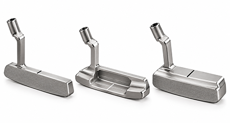
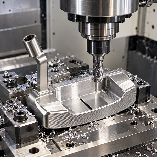
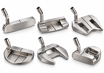
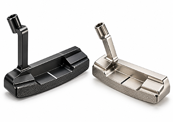
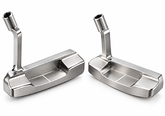
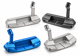
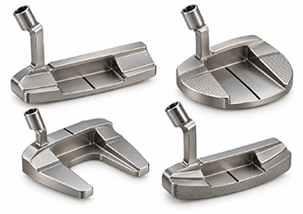
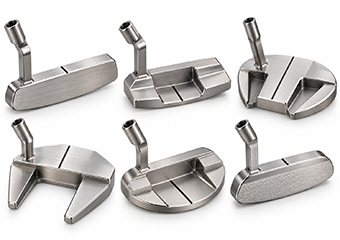
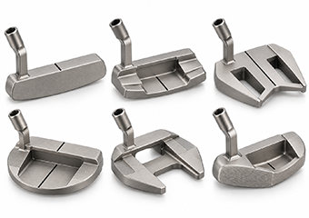
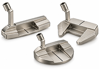
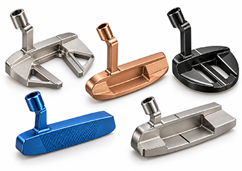
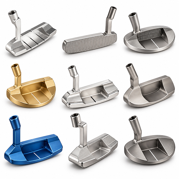
A putter head should not be assigned to 5-axis machining simply because the geometry looks complex. Start by identifying which surfaces must be reached, which datums must stay related and how many times the part can be repositioned without creating unnecessary variation. A compact blade may be efficient on 3-axis or 3+2 equipment, while a mallet with deep rear cavities, angled neck features or multiple side-access requirements may benefit from 3+2 or 5-axis machining.
The practical goal is not to use the highest-axis machine available; it is to select the route that gives stable workholding, efficient tool access and repeatable control of the features that matter. During DFM, VMT reviews stock orientation, fixture references, cavity access and finishing allowance before selecting the machining sequence. This helps prevent a project from becoming more expensive simply because the process was chosen before the geometry was fully understood.
2. Select Material Together With Head Architecture and Finish
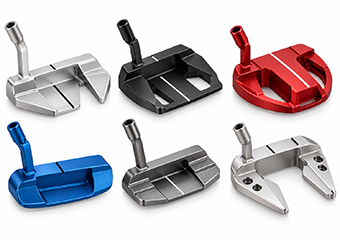
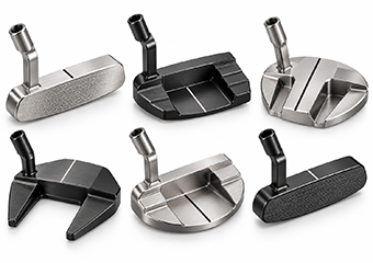
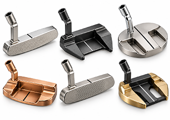
Material selection is not only a question of strength. It changes the volume of metal required, cutting behavior, available finishing routes and how the head can be divided into multiple components. 303 stainless steel is often practical for dense, detailed stainless designs because it machines well and supports brushed, polished, passivated or PVD finishes. 6061-T6 aluminum is much lighter, making it useful when a larger mallet body or chassis needs more volume without the mass of a comparable stainless component.
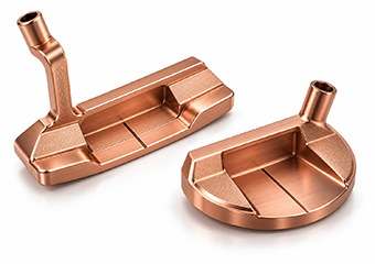
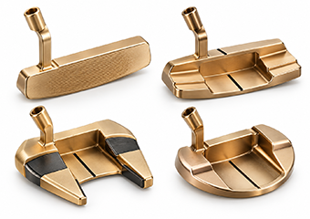
7075-T6 can be reviewed where higher strength or rigidity is useful at lower mass, while 1018 carbon steel, copper, brass, aluminum bronze and Titanium Grade 5 may suit project-specific heads, inserts, accents or weight-related components. The better decision comes from reviewing the complete architecture: body size, target weight, insert strategy, surface finish and quantity. If several materials are still under consideration, send the CAD model and intended finish so the manufacturing trade-offs can be reviewed before the design is frozen.
3. Design Mallet Cavities for Real Cutter Access
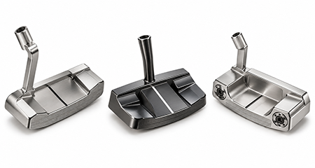
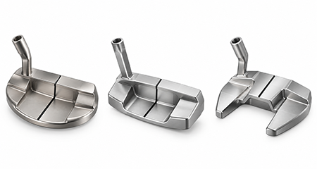
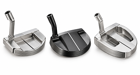
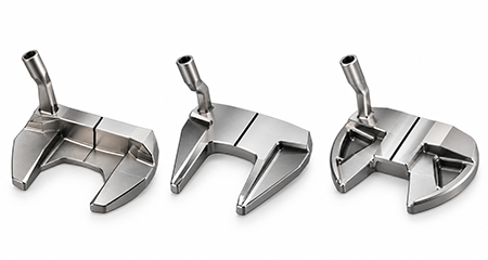
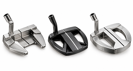
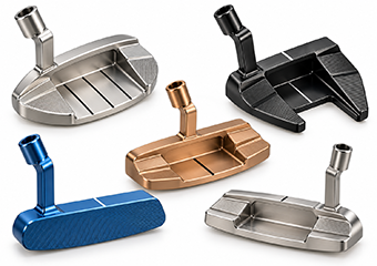
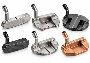
Large mallet heads often create cost and stability problems through deep cavities, narrow channels, thin wings and small internal radii. Deep features may require long-reach cutters, while small corner radii force the use of smaller tools. Both reduce stiffness and can increase vibration, cycle time and sensitivity to tool deflection. Thin rear structures may also react to clamping pressure or unbalanced material removal.
During DFM, review which internal radii are truly function-critical and which are only visual. Where the design allows it, larger practical radii and more direct cutter access usually simplify machining. For very deep pockets, staged roughing and semi-finishing may be preferable to aggressive one-pass removal. The aim is not to simplify the appearance of the product; it is to distinguish features that define the design from features that create machining difficulty without adding customer value.
4. Define the Putter Face as Engineering Geometry
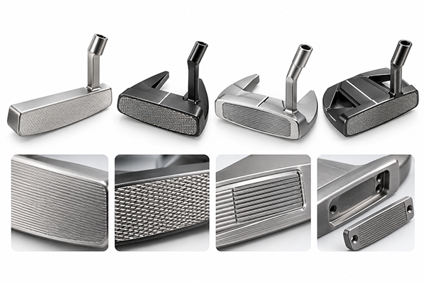
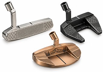
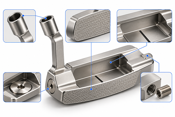
A reference photograph can show the visual direction of a putter face, but it cannot define a repeatable CNC process. If the face pattern is important, the manufacturing package should identify the applicable groove width, depth, spacing, direction, boundary, transition area and insert geometry. The controlling datum should also be clear so the face can be related back to the head body during both machining and inspection.
This is especially important for multi-depth patterns or insert-ready designs. Without measurable geometry, prototype and production parts can look similar while still being manufactured differently. VMT uses the CAD model and drawing to plan tool selection, cutting sequence and inspection. Golf-performance outcomes remain the customer’s responsibility, while VMT’s role is to reproduce the approved face geometry consistently and protect that definition through finishing.
5. Build a Clear Datum Chain for the Face, Body and Shaft Interface
A shaft bore is not always just a diameter. In center-shaft, direct-bore or custom-neck designs, position, angle, depth and relationship to the face may all matter. If every feature is dimensioned independently without a clear datum strategy, each measurement can pass while the overall geometric relationship still fails during assembly or product validation.
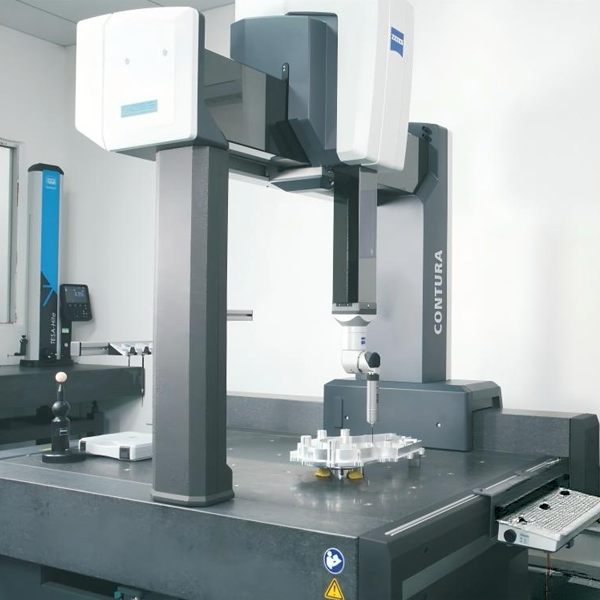
Before machining begins, identify which surface or feature should control the part orientation and which interfaces must be measured from that reference. The same thinking applies to face inserts, sole plates and weight pockets. VMT can use CMM or other suitable dimensional methods where the drawing requires multi-datum verification, but inspection becomes much more meaningful when the drawing defines the relationships the product actually depends on.
6. Treat Multi-Material Heads as One Assembly, Not Separate Parts
A multi-material putter head may combine a stainless front section, aluminum chassis, face insert, sole plate and separate weight components. The individual pieces can all pass inspection and still assemble poorly if locating surfaces, fastener positions, pocket depths or finish boundaries are not controlled from the same assembly definition.
Review each mating interface in the final finished condition. A pocket that fits correctly before anodizing or plating may become too tight afterward, while a locating face that is polished aggressively can change how two components sit together. For repeat production, the assembly drawing should define the component relationships that matter, and the inspection plan should include those interfaces rather than relying only on isolated part dimensions.
7. Plan Surface Finishing Before Final Machining Begins
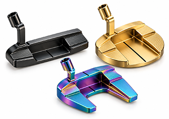
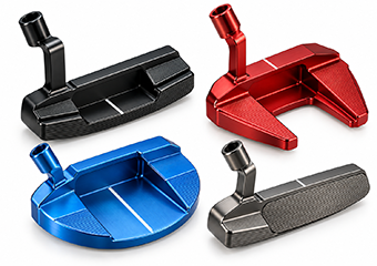
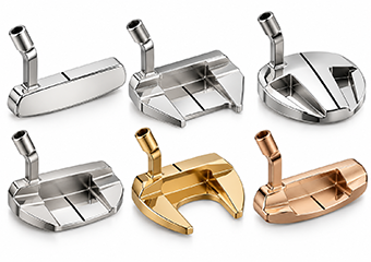
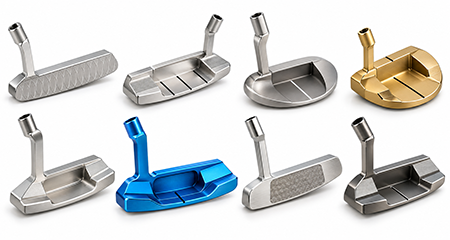
Surface finishing affects both appearance and dimensional condition. Satin brushing, bead blasting, anodizing, PVD, electroless nickel plating, polishing and laser engraving all interact differently with the base material and surrounding geometry. Shaft bores, threads, face features, insert pockets and weight interfaces may need masking, machining allowance or post-finish verification.
Appearance-critical heads should also define what “acceptable” means. Finish consistency, brush direction, protected areas, visible transitions, scratches and marking position may need separate cosmetic criteria in addition to dimensional inspection. VMT coordinates machining and finishing so the final part is evaluated in the condition the customer will actually assemble and receive, not only in the unfinished CNC state.
8. Control Cost by Improving RFQ Information, Not by Removing Every Precision Requirement
The main cost drivers are material, billet size, total material removal, setup count, cutter access, small internal radii, face detail, surface finishing, inspection requirements and quantity. A large mallet can cost more than a smaller blade because much more metal must be removed and more surfaces may require controlled access. Conversely, specifying unnecessary tight tolerances on cosmetic features can also add machining and inspection time without improving product function.
For a useful quotation, send the 3D CAD model, material or material options, quantity, project stage and finish if known. Add a 2D drawing for critical tolerances, datums, threads, face definition, weight requirements and inspection notes. If the product already exists, an approved sample and previous inspection information can help a new supplier understand the manufacturing baseline. Better RFQ information allows the quote to reflect the real manufacturing risk instead of relying on assumptions.
 +86 15099911516
 inquiry@vimetal.com.cn



 1–5 Day Prototype Support for New Putter Head Designs