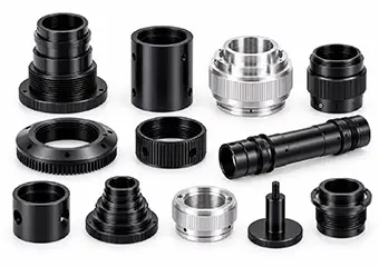
Precision Optical Lens Barrels
Precision lens barrels locate lens groups; CNC turning finishes bores, shoulders and OD datums, controlling concentricity before dimensional inspection confirms repeatable assembly fit.

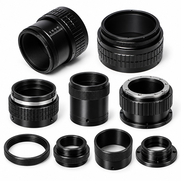
VMT provides custom CNC optical lens barrel and lens housing machining with ±0.005 mm precision capability DFM review CMM inspection surface finishing prototype and repeat production support.
 Proven ±5 μm Lens Barrel ID Control on 0.8 mm Thin-Wall Parts
Bore-to-OD Concentricity & Datum Control for Reliable Optical Assembly
Thin-Wall Fixture Optimization to Reduce Clamping Distortion and Bore Shift
Post-Anodizing Bore, Thread & Lens-Seat Inspection for Consistent Finished Fit
4-Hour DFM Review + CMM Inspection from Prototype to Repeat Production
1 DayPrototyping Machining
2 HoursQuick Quote
0 PcsMinimum Order Qualities
98%Yield


Whether you need precision lens barrels, multi-step housings, retaining rings, focus components, optical tubes or custom mounting structures, VMT provides build-to-print prototype and production solutions based on your drawings and application requirements.
With experience supporting OEM manufacturers, optical-system developers, equipment builders, imaging brands and industrial technology companies, we turn your mechanical design, optical positioning concept and assembly requirements into precision machined components. CNC turning, CNC milling, turn-mill machining, 5-axis machining, surface-finishing coordination and dimensional inspection are planned together to control bores, concentric relationships, lens seats, fine threads, thin walls and mating interfaces.
Choose from aluminum, stainless steel, brass, titanium, Invar and engineering plastics to balance weight, rigidity, thermal behavior, corrosion resistance, surface appearance and cost. From concept review and prototype validation to repeat production, VMT helps reduce manufacturing risk, improve assembly consistency and move optical mechanical designs into production with a controlled machining and inspection plan.
VMT machines custom optomechanical components from customer drawings rather than selling fixed catalog parts, with each structure planned around its functional bore, thread, datum, surface and assembly requirements.
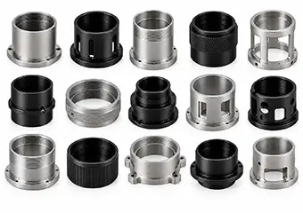
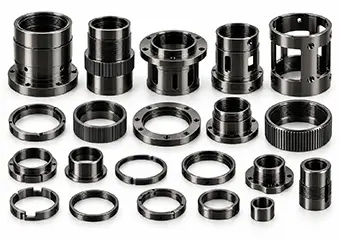
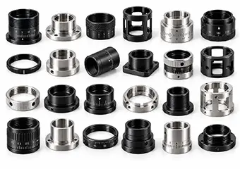
Precision lens barrels locate lens groups; CNC turning finishes bores, shoulders and OD datums, controlling concentricity before dimensional inspection confirms repeatable assembly fit.
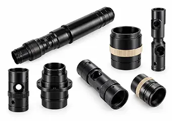
Multi-step barrels position multiple lenses; CNC turning and boring machine stepped IDs and seats, controlling axial stack-up before CMM inspection verifies critical relationships.
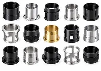
Thin-wall barrels reduce mass; staged turning with optimized workholding limits clamping distortion, then released-part inspection confirms bore and OD stability before finishing.
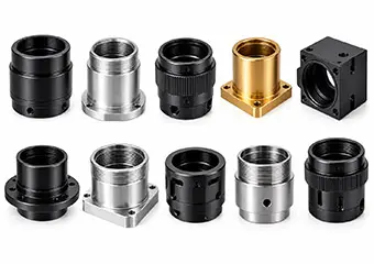
Lens housings support optics and mounting interfaces; CNC milling and turning create bores, flanges and side features, with datum-based inspection confirming assembly alignment.
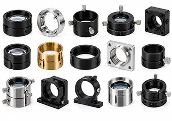
Lens cells retain individual optics; precision turning machines seats, shoulders and threads, controlling fit and axial position before dimensional inspection verifies the mating interface.
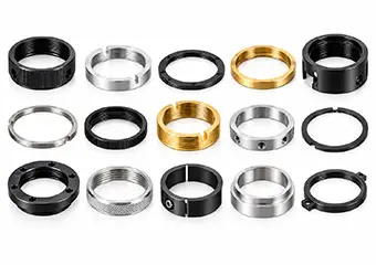
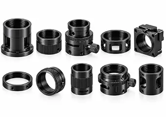
Retaining and spacer rings secure optical stacks; CNC turning controls thickness and fine threads, followed by deburring and fit inspection for reliable assembly.
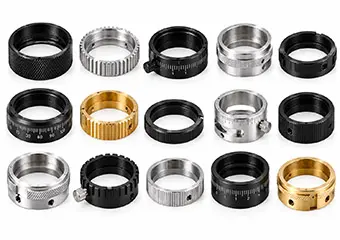
Focus and adjustment rings provide controlled movement; turning and milling produce threads and grip features, with fit inspection confirming smooth, repeatable mechanical adjustment.
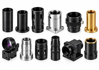
Optical tubes connect lens groups and housings; turning and multi-axis machining control bores, flanges and threaded ends before final inspection verifies assembly relationships.
VMT is a build-to-print manufacturer, not a catalog supplier. Send your drawing so the process can be reviewed around the real geometry, tolerance stack, finishing and inspection requirements of your part.
A lens barrel is a system of related features. Bore size, lens-seat position, threads, OD datums and mounting faces must be controlled in the relationships defined by the drawing—not as isolated dimensions.
Critical bores are reviewed for size, depth, geometry and measurement access so the selected machining method matches the functional fit.
Related cylindrical features are planned around controlled references to reduce axis shift caused by unnecessary datum transfers.
Shoulders and seats are controlled from meaningful datums because they define where lenses, cells or spacers stop along the barrel axis.
Fine retaining or interface threads are reviewed together with the bore and mating features that determine final assembly fit.
Workholding, stock removal and release from the fixture are considered where wall thickness makes the part sensitive to distortion.
Bores, threads and mating surfaces are reviewed in their finished condition when anodizing or plating may affect fit.
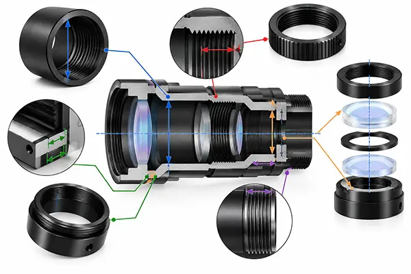
A barrel can pass separate diameter, thread and length checks yet still create assembly problems if those features do not share the required datum relationship. VMT reviews the GD&T, functional datums and mating interfaces together before the machining plan is finalized.
The machining route depends on the barrel structure, datum logic, bore depth, wall thickness and side features, so VMT combines turning, milling, turn-mill, multi-axis machining, fixture control and staged finishing according to the drawing.

Used for OD, stepped ID, lens seats, shoulders and fine threads that share a controlled rotational datum and require stable cylindrical relationships.
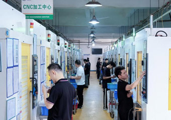
Used for flanges, slots, mounting faces, pockets and hole patterns where prismatic features must be controlled to the barrel datum structure.
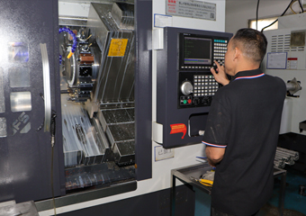
Where geometry permits, turning and milling are combined to reduce datum transfers between central bores, radial holes, flats and flange features.
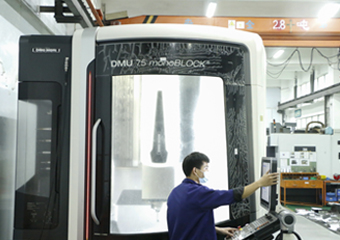
Used for multi-sided holes, angled faces, windows and integrated mounting structures when fewer re-clamping steps help preserve datum relationships.
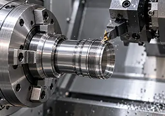
Support area, clamping position and access are reviewed to reduce fixture-induced distortion around thin walls, critical bores and mating surfaces.

Roughing, semi-finishing, critical-feature finishing and intermediate checks are separated when material removal or part stability requires a controlled sequence.

The actual sequence is defined after review of material, geometry, GD&T, finishing and production requirements.
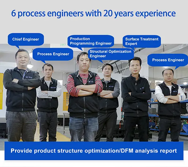
DFM should convert drawing requirements into a measurable manufacturing plan. VMT reviews datums, critical diameters, thin walls, threads, finishing and inspection access before material is cut, then defines how each risk will be controlled and verified.
| DFM Review Item | Main Risk | VMT Review & Control | VMT Inspection / Result |
|---|---|---|---|
| Datum Structure | Bore, OD, thread or mounting features pass separately but misalign in assembly. | Define the primary axis / face and keep related features in the same datum chain where geometry allows. | CMM / 3D measurement is referenced to drawing datums; first-article and final results can be recorded in the dimensional report. |
| Precision Bores & OD | Size variation, taper or axis shift affects lens / housing fit. | Critical diameter targets are reviewed together; suitable precision features can be machined to ±0.005 mm after engineering review. | First article plus in-process dimensional checks; critical dimensions are 100% checked where specified before final release. |
| DFM Review Item | Main Risk | VMT Review & Control | VMT Inspection / Result |
|---|---|---|---|
| Lens Seats & Thin Walls | Clamping or stock removal changes seat position or released-part geometry. | Review wall thickness, support area, machining sequence and when final bore / seat finishing should occur. | Recheck bore, OD and seat relationship after unclamping; prototype / first article must meet drawing requirements before repeat production. |
| Tool Access & Fine Threads | Internal shoulders, undercuts or fine threads restrict tooling and create fit risk. | Review relief, access, thread form and whether finishing changes the mating condition. | Thread / dimensional gauges and functional checks are selected to the drawing; finished threads are rechecked when coating can affect fit. |
| Surface Finish | Anodizing or plating changes functional dimensions or cosmetic appearance. | Identify finished-condition dimensions, masking areas, machining allowance and cosmetic surfaces before release. | VMT's finishing control includes SQE follow-up, post-finish critical-dimension checks where required and 100% appearance inspection after return. |
| Inspection Feasibility | A feature can be machined but cannot be measured reliably. | Confirm datum setup, measurement access and report requirements before production. | CMM / 3D, 2D, height, thread and roughness measurement methods are selected by feature; full dimensional reports are available when required. |
DFM recommendations are based on the supplied drawing, geometry, material, tolerance, finishing and production requirements. Functional design changes are implemented only after customer confirmation.
VMT does not change functional dimensions, GD&T, material or surface-finish requirements without customer confirmation. DFM feedback is used to identify manufacturing, finishing or inspection risks and discuss practical options before the project is released for production.
Material selection affects weight, rigidity, thermal behavior, machining stability, finishing and cost, so VMT reviews the grade together with geometry and functional interfaces before confirming the process route.
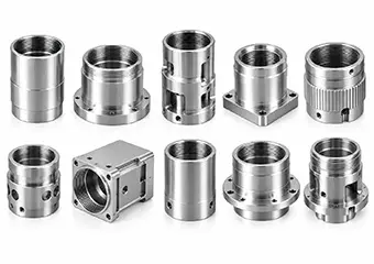
6061-T6 suits lightweight lens barrels, combines good machinability with corrosion resistance, accepts black anodizing well, and helps balance dimensional control, appearance and production cost.
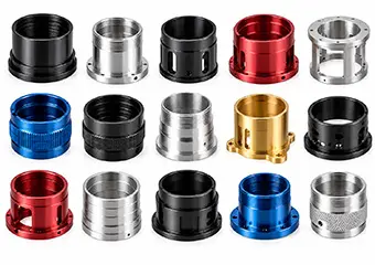
7075-T6 suits high-strength lightweight housings, provides greater rigidity than common aluminum grades, supports anodizing, and helps reduce section size while maintaining structural performance.
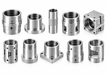
6063 suits optical tubes and cosmetic housings, offers good extrusion and machining behavior, responds well to anodizing, and supports lightweight parts with consistent exterior appearance.
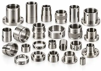
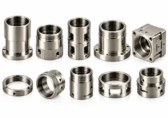
Stainless steel suits lens cells and threaded interfaces, provides rigidity and corrosion resistance, accepts passivation or polishing, and supports durable precision mating surfaces in demanding assemblies.
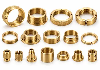
Brass suits retaining rings and adjustment components, machines cleanly into fine threads, supports nickel or black finishes, and helps achieve smooth assembly with controlled small features.
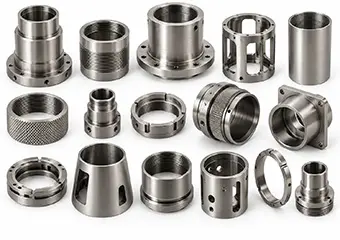
Titanium suits high-performance lightweight optical structures, combines strength with corrosion resistance, accepts PVD or passivation-type finishes, and provides durability where mass and environment matter.
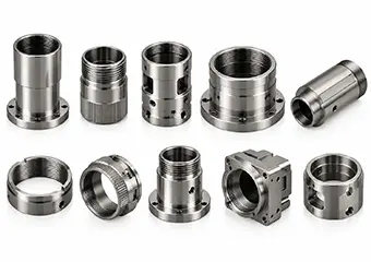
Invar 36 suits thermally sensitive optical structures, offers very low thermal expansion, accepts protective finishing as specified, and helps limit temperature-driven dimensional change in precision assemblies.
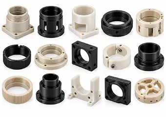
PEEK or POM suits insulating and lightweight optical supports, provides low mass and easy machining, needs application-specific finishing review, and helps reduce weight or electrical conduction.
Typical room-temperature reference values are shown for engineering comparison only; exact properties vary by temper, alloy specification and supplier certificate and should be confirmed during DFM.
| Design Priority | Material | Key Considerations | Typical Finish / Design Value |
|---|---|---|---|
| Lightweight + anodized housing | 6061-T6 / 6063 Aluminum | Density ≈ 2.70 g/cm³; elastic modulus ≈ 69 GPa. Review wall thickness, bore depth and post-machining stability. | Type II / black anodizing; balanced weight, machinability, appearance and cost for lens barrels and optical housings. |
| Higher-strength lightweight structure | 7075-T6 Aluminum | Density ≈ 2.81 g/cm³; elastic modulus ≈ 72 GPa. Thin walls and heavy stock removal require closer distortion review. | Type II / Type III anodizing; higher strength and stiffness where the design needs more structural margin without switching to steel. |
| Durable lens cells / threaded interfaces | Stainless Steel | Higher rigidity and wear resistance than aluminum; machining heat, burr control and thread quality require process attention. | Passivation / polishing / electropolishing as specified; supports durable mating surfaces and corrosion resistance. |
| Fine threads / adjustment components | C360 Brass | Density ≈ 8.49 g/cm³; good fine-feature machinability and stable thread cutting for small retaining or adjustment parts. | Nickel / black nickel / polishing; helps achieve smooth assembly and controlled small threaded features. |
| High strength-to-weight / corrosive environment | Ti-6Al-4V Titanium | Density ≈ 4.43 g/cm³; elastic modulus ≈ 114 GPa; CTE ≈ 8.6 µm/m·K. Heat and tool engagement must be controlled. | PVD / DLC or specified protective treatment; useful where mass, strength and corrosion resistance all matter. |
| Thermally sensitive optical structure | Invar 36 | CTE ≈ 1.2 µm/m·K near room temperature; material condition, machining stress and datum strategy need review. | Protective finish as specified; helps reduce temperature-driven dimensional change in precision optomechanical assemblies. |
| Insulating / lightweight support component | PEEK / POM | Low density and electrical insulation; consider creep, temperature and load before using plastic for a locating or structural feature. | Usually used as-machined or with application-specific treatment; reduces mass and avoids electrical conduction where required. |
The finish must support optical-mechanical function as well as appearance. VMT reviews coating buildup, masking, critical fits, internal surface requirements and post-finish inspection before releasing the finishing route.
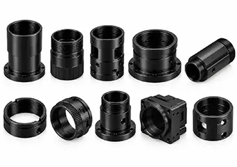
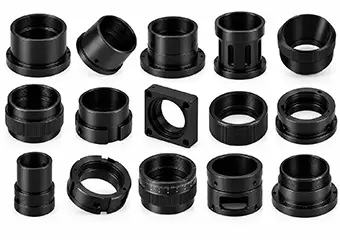
Aluminum lens barrels use Type II black anodizing for corrosion resistance and dark appearance, while finished bores and threads are controlled to preserve assembly fit.
Aluminum optical housings use bead blasting before black anodizing to create a more uniform matte surface, reduce visible machining marks and improve cosmetic consistency.
Aluminum adjustment and wear interfaces use hard anodizing for higher surface hardness, while masking and finished-size planning protect threads, sliding fits and assembly clearances.
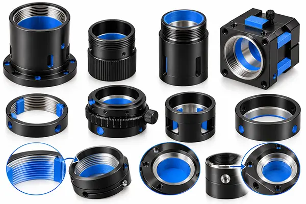
Internal lens-barrel surfaces can use specified optical-black coatings to reduce unwanted internal reflection, with critical seats and threads protected so optical and mechanical requirements remain compatible.
Precision optical housings use electroless nickel for uniform protection and wear resistance, while coating allowance is reviewed around bores and mating surfaces to maintain finished fit.
Special optical or instrument parts use black nickel for a dark decorative and protective surface, helping reduce glare while maintaining controlled interfaces through finished-dimension inspection.
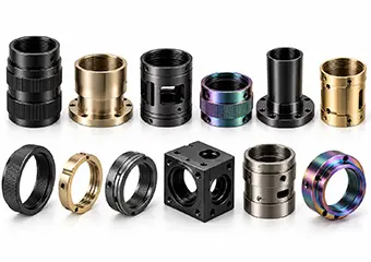
Sliding or wear-sensitive optical components can use PVD or DLC for lower friction and wear resistance, with coating selection reviewed against mating fit and functional surfaces.
Lens housings and adjustment rings use laser marking for model, scale, serial or assembly identification, adding durable traceability without changing critical precision interfaces.
| Critical Feature | Functional Requirement | Finishing Risk | VMT Control Approach |
|---|---|---|---|
| Precision Bore | Lens / cell locating fit and repeatable radial position | Coating buildup changes finished ID or clearance | Finished tolerance is defined from the drawing; use allowance or masking as specified, then 100% check critical IDs where required. Suitable precision machining capability can reach ±0.005 mm after process review. |
| Lens Seat / Shoulder | Axial seating and stack-up position | Coating changes contact surface or axial stack | Identify the surface as functional before finishing, protect / mask where required, and verify the finished seat-to-datum relationship. |
| Critical Feature | Functional Requirement | Finishing Risk | VMT Control Approach |
|---|---|---|---|
| Fine Internal Thread | Retaining-ring or mating-component engagement | Pitch diameter becomes tight after anodizing / plating | Review thread allowance, masking and coating specification; verify with thread / functional checking after finish when fit is critical. |
| Mating OD / Locating Hole | Slip, transition or assembly clearance | Finished size closes the intended clearance | Plan the required finished dimension before machining, then recheck mating diameters after finishing before final release. |
| Datum / Mounting Face | Flat contact, alignment and assembly stack-up | Coating changes contact condition or perpendicular relationship | Protect datum faces when required by the drawing and verify critical GD&T relationships after the full process route. |
| Cosmetic Exterior | Uniform color / texture with no unacceptable handling damage | Tool marks, color variation or scratches after finishing | SQE follows the finishing process; VMT performs 100% appearance inspection after parts return and uses protective packaging for cosmetic surfaces. |
There is no single universal “coating error” for every anodizing, nickel or PVD process because buildup varies with specification, material and geometry. VMT therefore controls critical features to the finished drawing requirement, defines allowance / masking during DFM and re-inspects the functional interface after finishing where required.
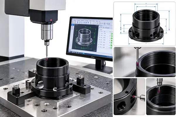
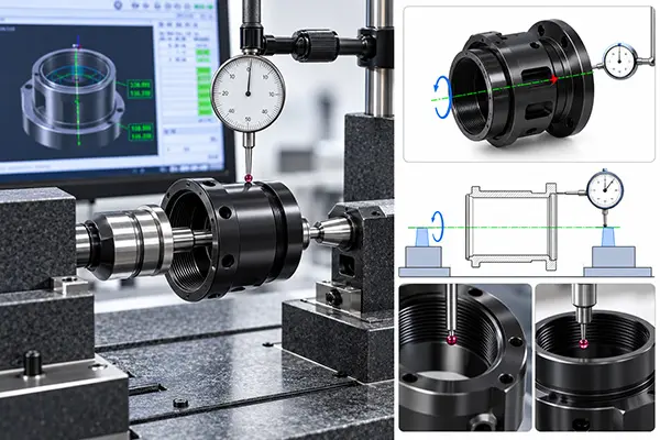
Inspection is planned around the feature function, drawing datum and production stage. VMT combines first-article inspection, in-process checks, CMM / 3D measurement and final verification so critical lens-barrel dimensions are supported by recorded measurement rather than visual judgment.
| Critical Feature | What Must Be Proven | VMT Inspection Method | Inspection Frequency / Result |
|---|---|---|---|
| Precision Bore / ID | Lens / cell fit, size stability and bore geometry | First article plus CMM / 3D or suitable precision dimensional measurement selected for bore depth and access. | In-process dimensional checks are performed during production; suitable critical features can support ±0.005 mm after drawing review, with 100% critical-dimension inspection where specified. |
| Bore-to-OD Coaxiality / Runout | Internal and external axes remain within drawing GD&T | CMM establishes the specified datum axis and measures related cylinders / faces; runout verification is used when it matches the drawing method. | Verified on first article and again at final inspection; datum relationship is recorded in the dimensional report when required. |
| Lens Seat / Shoulder | Axial lens-stack position and seating relationship | CMM / 3D or suitable height / depth measurement referenced to the drawing datum face. | First article confirms the process; critical seat dimensions are checked again before release and can receive 100% inspection when specified. |
| Fine Thread / Retaining Thread | Correct thread form, engagement and mating fit | Thread gauge / dimensional verification and functional mating check where required; access and coating condition are considered. | Checked before finishing and rechecked after anodizing / plating when the coating can affect engagement. |
| Mounting Face / Hole Pattern | Flatness, perpendicularity, position and assembly interface | CMM / 3D, 2D measurement or height-based inspection selected according to geometry and datum definition. | First article + final inspection to the GD&T on the customer drawing; inspection report available when required. |
| Surface Roughness | Specified functional / cosmetic surface condition | Roughness gauge on drawing-specified surfaces; VMT machining capability can reach Ra 0.2 μm on suitable features. | Measured according to the drawing requirement and recorded when roughness is a controlled characteristic. |
| Post-Finish Critical Features | Finished fit plus cosmetic acceptance after anodizing / plating | Recheck critical bores, threads and mating features after finishing; appearance inspection is separated from dimensional verification. | Critical interfaces are remeasured where required, and VMT performs 100% appearance inspection after parts return from finishing. |
VMT's quality-control process includes first-article verification, in-process dimensional checks and final inspection against the drawing. For critical GD&T, deep bores or post-finish fits, the measurement method is confirmed during DFM so the feature can be both manufactured and proven.
This published VMT project shows how drawing review, dedicated fixtures, toolpath optimization, surface-finishing control and full dimensional inspection were combined for a high-volume optical enclosure.
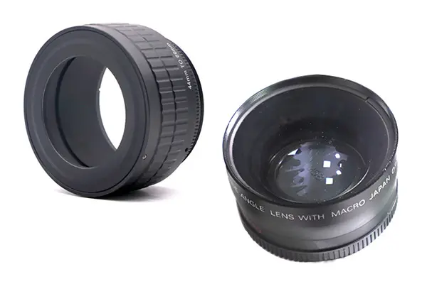
The customer specified AL6063-T6, full dimensional inspection, a Class A visible surface with no unacceptable tool marks, black oxidation and a production requirement of more than 3,000 pieces per day. The structure contained more than 100 dimensions, and approximately 60% of those dimensions had tolerances below 0.02 mm.
The project combined dense dimensional inspection with demanding cosmetic requirements. The published case records that the customer had already tested six CNC machining suppliers without meeting the required quality level, so VMT needed to control both geometry and the appearance before and after black finishing.
VMT reviewed the customer drawing and calculated the relationship between in-process machining dimensions and the final required dimensions so the finished part could meet the drawing after the complete process route.
Special tooling and fixtures were developed, and programming / toolpath parameters were optimized around the enclosure geometry to reduce visible tool marks on Class A external surfaces before finishing.
The case used 3D dimensional inspection for the enclosure and 220# glass-sand blasting before black oxidation, combining full dimensional verification with controlled cosmetic preparation.
The published project records that VMT completed the proofing in three days and shipped within one week, while the final camera lens ring enclosure was repeatedly verified by the customer. The reported shipment defect level and defective assembly rate were both controlled within 3%, and the structure and appearance exceeded the customer's original requirements.
VMT machines lens barrels, lens cells, optical tubes and housings for systems that need stable mechanical positioning of optical elements, controlled interfaces and repeatable production from customer drawings.
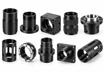
Lens barrels, cells and optical tubes for imaging systems where bore relationships, mounting interfaces and repeatable sensor / lens positioning support stable inspection performance.
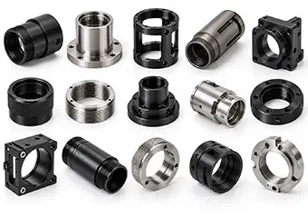
Custom barrels, collimator housings and optical tubes with controlled bores, threads and internal finishes for laser, photonics and optical-mechanical assemblies.
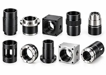
Compact lens cells, housings and barrels manufactured to customer drawings where controlled fit, clean surfaces and documented dimensional inspection support equipment assembly.
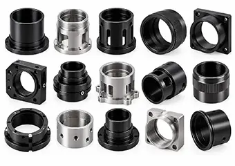
Optomechanical structures for measurement instruments where lens positions, reference datums and mounting interfaces must remain controlled across prototype and repeat production.
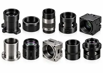
Compact barrels and housings for camera and sensing modules where dimensional repeatability, black finishing and production consistency are critical to mechanical integration.
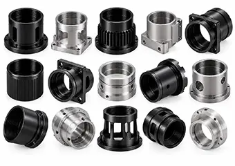
Lightweight optical housings and barrels using aluminum, titanium or other specified materials where thin walls, multi-axis features and mass reduction influence the machining route.
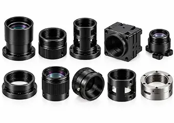
Multi-section barrels, lens cells and adjustment components with stepped bores, fine threads and mating interfaces for long-range imaging and security optical assemblies.
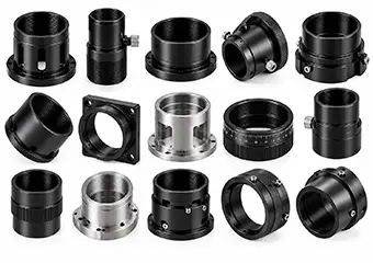
Long optical tubes, objective housings, lens cells and retaining components machined from drawings where bore, flange and axial relationships support the instrument structure.
A prototype proves the process direction; repeat production requires the validated datum strategy, fit, finishing, inspection method and handling controls to remain consistent across later batches.
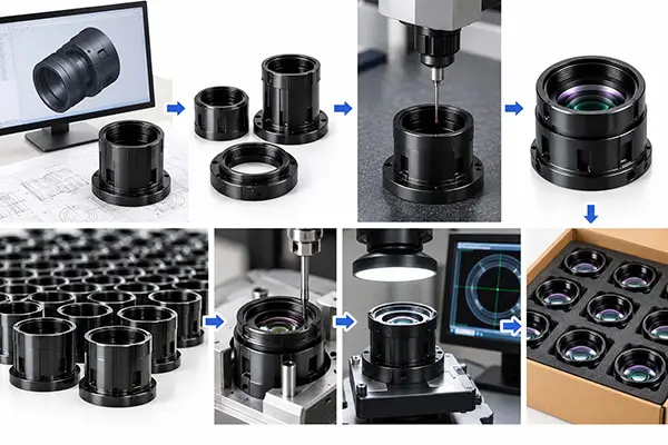
| Validation Area | What We Validate | VMT Check / Data | Repeat-Production Benefit |
|---|---|---|---|
| Precision Bore | Diameter, bore geometry and mating fit | First article + in-process measurement; suitable critical features can support ±0.005 mm after drawing review, with 100% critical checks where specified. | More stable bore production and lower fit variation. |
| Coaxial / Datum Relationship | Bore, OD, thread and mounting reference stay in the required datum chain | CMM / 3D datum-based verification on first article and final inspection. | Lower setup-related axis variation between batches. |
| Lens Seat / Shoulder | Axial seat location and lens-stack interface | CMM / height / depth method selected to geometry; critical seats can be 100% checked where required. | More consistent axial positioning and stack-up. |
| Fine Threads | Mating condition before and after finishing | Thread gauge / dimensional or functional check; re-inspection after coating when finished fit is critical. | Reduced binding, looseness and retaining-ring issues. |
| Thin Walls | Geometry after release from fixture | Recheck bore / OD after unclamping and before process approval. | Lower deformation risk when the same fixture and sequence are repeated. |
| Black Anodizing | Finished fit, color / texture and protected interfaces | Critical dimensions rechecked where required; VMT performs 100% appearance inspection after parts return from finishing. | More predictable assembly fit and batch appearance. |
| Cosmetic Finish | Visible-surface acceptance criteria | Approved sample defines appearance expectations; final appearance inspection separates scratches / marks from dimensional acceptance. | Clearer cosmetic standard for repeat orders. |
| Inspection Method | Measurement access, datum setup and report format | First article is verified before repeat production; in-process dimensional checks are performed during production and final reports can be supplied. | The same verification logic is carried across batches. |
| Packaging | Protection of cosmetic and precision surfaces | Packaging method is selected by geometry and finish; VMT commonly uses protective materials such as pearl cotton / bubble packaging where appropriate. | Lower handling and transport-damage risk. |
VMT uses approved prototype or first-article results to standardize key machining, finishing, inspection and handling controls before repeat production. Any functional drawing change remains subject to customer confirmation.
The more clearly the drawing identifies functional dimensions, finished-condition requirements and inspection expectations, the faster VMT can review manufacturability and build an appropriate machining plan.
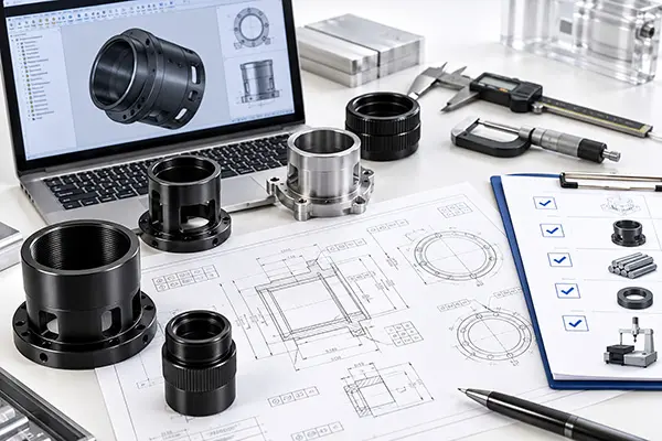
| RFQ Information | What to Send | Why It Matters |
|---|---|---|
| 2D Drawing | Dimensions, tolerances, GD&T and datum references | Defines critical bore, lens-seat, thread and datum relationships for process and inspection planning |
| 3D CAD Model | Complete part geometry | Helps review deep bores, thin walls, internal shoulders, side features and tool access |
| Material & Condition | 6061-T6, 7075-T6, stainless steel, Invar or specified grade / temper | Material affects machining stability, cutting strategy, workholding, finishing and cost |
| Critical Dimensions | Bore, runout / concentricity, lens seat, thread, mounting datum | Helps prioritize machining controls, inspection method and reporting |
| Surface Finish | Black anodizing, hard anodizing, plating, PVD / DLC, marking or other specified finish | Determines allowance, masking, cosmetic criteria and post-finish inspection needs |
| Prototype / Production Quantity | Initial prototype quantity and expected repeat volume | Influences fixture strategy, tooling, inspection planning and production routing |
| Mating-Part Information | Lens cell, spacer, retaining ring, housing or mating fit data when available | Helps review thread engagement, assembly clearance and tolerance relationships |
| Inspection Requirements | Critical reports, FAI, material records or special verification | Allows measurement access, equipment and documentation to be planned before production |
You can still start the review. Send the latest drawing or CAD model, estimated quantity and the issue that concerns you most. Material, finishing or inspection details that are still open can be identified during the engineering review.
After customers receive, test and assemble the parts we make, the feedback we receive is usually very direct: the parts work, the quality meets expectations, successful samples move into production orders, and the parts arrive protected. The comments below are taken from customer emails sent to VMT; customer names and company details are hidden for privacy.

“Your parts were perfect, thank-you. I want to order a production quantity soon.”
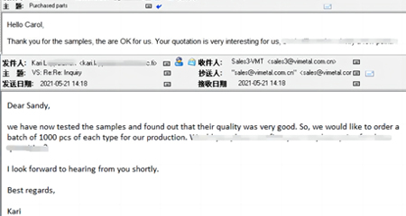
“We have now tested the samples and found out that their quality was very good. So, we would like to order a batch of 1000 pcs of each type for our production.”
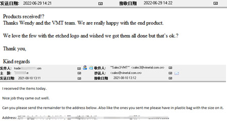
“Products received! Thanks Wendy and the VMT team. We are really happy with the end product.”

“They are perfect. I also want to say how amazed I am at the packing. Every part was securely packed and easy to access.”
For lens barrel and optical housing projects, our goal is the same: parts that meet the drawing, samples that can move into repeat production, clear communication when questions appear, and protective packaging that preserves dimensional and cosmetic surfaces through delivery.
Focused answers to the eight questions engineers and buyers most often need to resolve before sending a precision lens-barrel RFQ.
A useful lens-barrel drawing does more than list dimensions. It tells the manufacturer which features locate the optical elements, which datums control the assembly, which tolerances are functionally critical and which dimensions must be verified after finishing. The guide below combines design, machining and inspection considerations so engineering teams can reduce avoidable DFM loops before RFQ.
Define which bore, outside diameter, flange or face locates the lens barrel in the final assembly and which feature establishes the primary mechanical axis. If a bore, thread and mounting face must remain related, show that relationship in the datum structure instead of relying on separate ± dimensions. This helps VMT plan setups and CMM inspection from the same functional reference, reducing the risk that every feature passes individually while the assembled barrel still has axis or stack-up problems.
A lens-locating bore is rarely controlled by diameter alone. Engineers should also consider taper, roundness, bore depth and the relationship between the ID, OD, thread and mounting datum. For suitable features VMT machining capability can reach ±0.005 mm after review, but a tight size tolerance does not automatically guarantee a good axis relationship. Where concentricity or runout matters, define the datum and GD&T explicitly so machining and CMM verification can target the same requirement.
Lens seats, internal shoulders, spacers and retaining rings determine where each optical element stops along the barrel axis. Small variations can accumulate through a multi-element stack, so identify which seat is the functional reference and which dimensions actually drive optical-mechanical spacing. Avoid tightening every shoulder equally. Instead, control the critical seat-to-datum relationships, provide practical access for machining and measurement, and define any mating spacer or retaining-ring information needed to evaluate the complete axial stack.
Thin cylindrical walls reduce mass but also reduce machining stiffness. A barrel can measure correctly while clamped and then change after it is released. During design review, consider unsupported length, local wall transitions, heavy stock removal and where fixtures can safely apply force. VMT uses geometry-specific workholding and staged machining when required, but the drawing should still identify the features that must remain stable after unclamping so prototype inspection can verify the real free-state condition.
Fine internal retaining threads, focus threads and external mating threads should be reviewed together with nearby bores and lens seats. Give enough relief and tool access for machining, define the mating requirement clearly and specify whether the thread must meet size before or after finishing. If black anodizing or plating is applied, the coating can change thread engagement, so masking, machining allowance or post-finish thread verification should be planned before production rather than corrected after parts bind in assembly.
6061-T6 and 6063 are common when lightweight construction and anodized appearance matter; 7075-T6 may be considered where higher strength or stiffness is needed; stainless steel and brass suit selected rigid or threaded interfaces; titanium supports higher strength-to-weight requirements; and Invar 36 can be evaluated for thermally sensitive structures. The material also changes cutting behavior, workholding, distortion risk and available finishes, so final grade / temper should be confirmed before fixture and tolerance strategy are locked.
Internal barrel surfaces may need a dark, matte or low-reflective finish, but “black” alone is not a complete manufacturing specification. Identify which internal regions are functionally optical, which surfaces are lens seats or datums and which areas can accept blasting or coating. Surface roughness and texture should be specified where they are truly functional. VMT can coordinate machining and finishing, but critical seating surfaces, threads and precision bores should not be altered by an optical-black process unless that finished condition is intentionally designed.
Black anodizing is common on aluminum lens barrels, but it is not only a cosmetic step. It can change bore, thread and mating dimensions and can reveal tool marks after blasting or oxidation. Mark the finished-condition dimensions on the drawing, identify surfaces that require masking and define visible-surface acceptance criteria. VMT coordinates SQE follow-up at finishing suppliers, performs post-finish critical-dimension checks where required and conducts 100% appearance inspection after parts return.
A critical tolerance is useful only when it can be measured reliably. Deep bores, narrow shoulders and internal threads may restrict access, so the inspection approach should be reviewed during DFM. VMT uses first-article inspection to validate the initial route, in-process dimensional checks to monitor production and final inspection to release parts. When CMM / 3D measurement, thread gauges, roughness measurement or post-finish checks are required, those methods can be carried into repeat production so later batches are verified by the same logic.
Lens-barrel cost is driven by material, bore depth, wall thickness, tolerance, GD&T, fine threads, setup count, finishing, inspection and quantity. Ultra-tight tolerances on non-functional surfaces add machining and inspection cost without improving assembly. Mark the features that affect lens position, mating fit or optical-mechanical alignment first, then send the 2D drawing, 3D model, material / temper, finish, prototype and repeat quantity, mating-part information and inspection requirements. This gives VMT enough context to propose a process instead of quoting the geometry in isolation.
Send VMT your current lens barrel drawing or CAD model together with the critical bore, tolerance, material, finishing and quantity requirements already available. Our engineering team can review manufacturability, machining risks and inspection considerations before quotation, prototype machining and repeat production.

 2024-08-02
The manufacturer is strongly recommended. In the past few years of cooperation we have ordered several machined products from aluminum and stainless steel. These products are manufactured in compliance with tolerance requirements and require product finish. Now I have ordered another one. The service is excellent and any questions can be answered and resolved in time.
 2021-05-13
The dimensions are all customized according to my drawings no tolerance issues and the parts are delivered on time. I am very satisfied with it.
 2021-04-06
I pay much attention to the surface treatment aspect of this product. I was a little worried about the cooperation at the beginning. I am very satisfied with the product now and hope to cooperate for a long time.
 2022-09-22
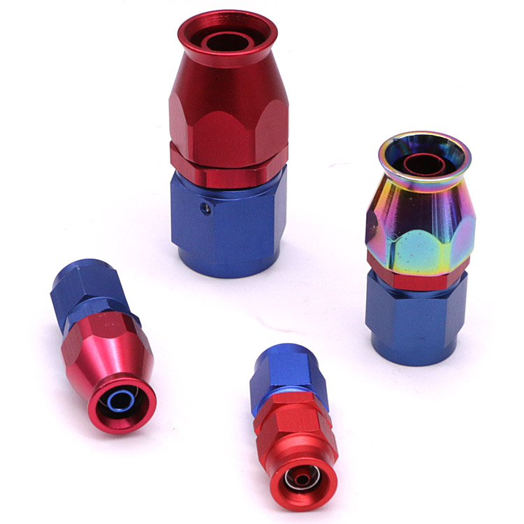
AN8 Straight PTFE Hose End Fitting for PTFE Fuel Line Fitting Adapter Black Blue Red


 +86 15099911516