15 years one-stop China custom CNC machining parts factory

Hey there I’m VMT Sam!
With 25 years of CNC machining experience we are committed to helping clients overcome 10000 complex part-processing challenges all to contribute to a better life through intelligent manufacturing. Contact us now
 0 |
Published by VMT at Jun 20 2026 | Reading Time:About 3 minutes
0 |
Published by VMT at Jun 20 2026 | Reading Time:About 3 minutes


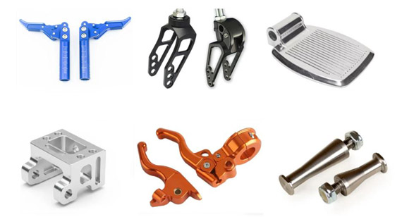
For CNC-machined racing parts, such as core components like pedals, caliper brackets, and gear shifters, any appearance of color discrepancies, alignment hole drift, or batch-to-batch tactile differences will inevitably lead to a poor user experience or even potential hazards once assembled. Ultimately, these defects directly impact brand premium, return rates, and customer retention.
CNC racing parts suit racing aftermarket brands doing small-batch, high-iteration, tight-tolerance custom production, covering engine bay, drivetrain/shift, brake/pedal, suspension/chassis, cockpit controls, and exterior styling — six part categories. 7075, titanium, and stainless are the three main materials; 5-axis simultaneous CNC + strict CMM inspection delivers consistent-look, stable-fit, low-after-sales parts in 2–4 weeks.
CNC machining stands out as the optimal process for these custom components: it seamlessly handles everything from single prototypes to small-batch production, maintains stable per-piece costs, allows for rapid design iterations, and achieves a quantifiable balance between material strength and lightweight design. This versatile combination of capabilities is something injection molding, die casting, stamping, or 3D printing can rarely deliver simultaneously.
This article explores the machining processes, types, and applications of CNC racing components, while offering practical references for DFM optimization. At the end of the text, we have included a practical case study from an Italian client served by VMT for your direct benchmarking and evaluation.

Selecting a custom manufacturing process typically requires balancing four core constraints: small-batch (or even one-off) production, high-frequency design iteration, exceptional aesthetic and dimensional consistency, and long-term reliability. Combined, these factors make CNC machining the irreplaceable, optimal solution for modern engineering projects.
Asset-Light and High Agility: Perfectly Matching Small-Batch Demand
In many innovative projects, the demand within a single product cycle may range from only 100 to 2,000 pieces, with the next generation facing rapid redesigns. CNC machining requires no hard tooling (molds/dies), meaning the per-piece cost for prototyping remains virtually identical to that of small-batch production. In contrast, traditional processes like die casting, injection molding, and stamping rely heavily on expensive and time-consuming mold development. Without sufficient volume, high tooling amortization eats away the entire profit margin.
High Precision and Robust Stability: Avoiding Batch-to-Batch Dimensional Drift
CNC machining ensures excellent repeatability across parts in terms of appearance, dimensions, and surface finish. A major pain point in production is "the first 100 pieces are perfect, but the next 100 begin to warp." Modern CNC processes address this by leveraging tool life management and in-process measurement systems, confining batch-to-batch dimensional drift strictly within ±0.01 mm to guarantee uncompromised, consistent quality.
Defect-Free and Predictable: Safeguarding Long-Term Durability
From a material reliability standpoint, CNC parts are machined out of solid stock (plates or bars), rendering them free of internal porosity, voids, or structural looseness. This leads to a highly predictable stress distribution, allowing the fatigue life to be accurately quantified through CAE simulation. Such predictability helps brands effectively mitigate the risk of sudden, batch-wide fatigue failures in the field, keeping the after-sales failure rate safely under control.
Ultra-Short Lead Times: Gaining a Head Start in R&D Iteration
It takes only 1 to 2 weeks from design freeze to having the physical parts in hand—an order of magnitude faster than mold-based processes, which typically take 8 to 16 weeks. This agility seamlessly aligns with the fast-paced development cadence of modern hardware products.
Parts fall into six functional categories and types. Each has different CNC process focus, main materials, and typical precision requirements.
| Category |
Typical Parts |
CNC Process Focus |
Main Materials |
| Engine bay |
Intake manifolds, throttle bodies, fuel rails, cam covers | 5-axis simultaneous, internal runner polish | 6061-T6, 7075-T7351 |
| Drivetrain & shift |
Shift forks, gear hubs, drive shafts, shift mechanism internals | High-precision grinding, post-heat-treat machining | 17-4 PH, 4140 |
| Brake & pedal |
Caliper brackets, brake pedals, brake line fittings | High stiffness, ultimate safety, assembly stability | 7075-T7351, titanium |
| Suspension & chassis |
Control arms, steering knuckles, links, shock tower tops | Topology optimization, lightweighting, fatigue resistance | 7075-T7351, titanium, 6061-T6 |
| Cockpit controls |
Steering wheel quick-release, shift mechanism, pedals, seat brackets | Assembly precision, grip feel, appearance | 7075-T7351, titanium, stainless |
| Exterior styling |
Decorative caps, fuel filler caps, badges, sill plates | Mirror finish, PVD, color consistency | 6061-T6, stainless, zinc alloy |
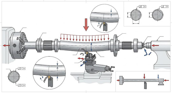
CNC racing part manufacturing involves four core processes, each tied to a set of key quality metrics. Understanding the process-to-metric relationship is the foundation for aligning technical specs with CNC suppliers.
| Process |
Application |
Key Quality Metric |
Typical Value |
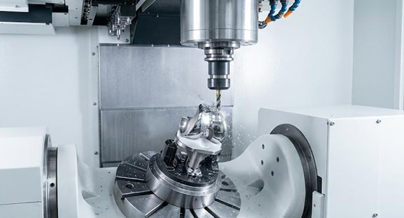
| 5-axis CNC machining |
Complex surfaces, conformal runners, topology-shaped parts | Dimensional tolerance | ±0.02 mm (IT6–IT7) |
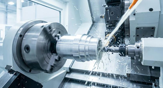
| High-speed precision milling |
Fit faces, appearance faces, highlight edges | Surface roughness | Ra 0.4–0.8 µm |
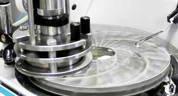
| Precision grinding & EDM |
Post-heat-treat distortion compensation, ultra-hard material finishing | Geometric accuracy | ±0.005 mm |
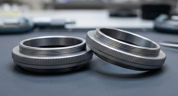
| Surface finishing |
Appearance parts, anti-corrosion parts, brand color consistency | Color difference | ΔE ≤ 1.0 |
Therefore, at the DFM stage, clarify which process each key feature uses, what metric it hits, and how it is inspected. Example: a caliper bracket's critical mounting holes use 5-axis simultaneous CNC + CMM; flatness uses coordinate measurement; appearance surfaces use high-speed precision milling + colorimeter.

Material selection for CNC-machined custom parts in racing and hypercar applications typically focuses on three core dimensions: extreme strength-to-weight ratio, high-temperature/corrosion resistance, and premium aesthetic appeal coupled with brand identity. Depending on the specific operating conditions, the primary material choices and their applications are detailed below:
7075-T7351 Aluminum —Premier Choice for Load-Bearing Structures
6061-T6 Aluminum — Balance of Aesthetics and Versatility
Ti-6Al-4V (Grade 5) Titanium — for Power-to-Weight Performance
17-4 PH (H1025) Stainless Steel —for Drivetrains and High-Strength Fasteners
4130 Chromoly Steel — Engineered for Tubular Frameworks
Application Scenarios: The industry standard for subframes and roll cages. These components are typically welded into shape first, followed by localized, high-precision CNC post-machining for critical mating faces and tolerances.
Advanced Engineering Plastics (PEEK / POM / Glass-Filled Nylon) — Low-Friction and Impact-Absorbing Components
Functional Deployment: PEEK retains its properties at continuous operating temperatures up to 260°C (ideal for hot zones); POM (Acetal) offers exceptional self-lubricating properties; Glass-Filled Nylon excels at impact energy absorption. These materials are widely specified for specialized gears, bushings, and seals.
Five typical part examples to show how CNC process varies across part types.
Case 1: Intake Manifold
Case 2: Shift Fork
Case 3: Brake Caliper Bracket
Case 4: Steering Wheel Quick-Release
Case 5: Sill Plate
Good DFM cuts CNC cost by 20–40% and shortens lead time by 30%. Six core DFM suggestions for racing parts are shown in the following:
Fillets first
Replace all inner and outer sharp edges with R0.5+ fillets. Sharp edges force the tool to slow down at the root, adding 50% machining time and risking chipping. 0.5 mm fillet is formed in one pass with a standard end mill; 0.2 mm fillet needs a ball mill and halves efficiency.
Uniform wall thickness
Keep wall thickness variation within 2:1. Example: a control arm main wall 8 mm, rib thickness 16 mm — 2:1 is single-pass machinable. 3:1+ leaves thin walls under-cut and thick walls tool-vibrating.

Lightening hole patterns, not pockets
Lightweight via regular lightening hole arrays, not pocketed bodies. Ø8 mm lightening holes with ≥ 15 mm spacing, ≥ 8 mm edge distance — lightens weight and preserves stiffness.
Unified locating datums
Each part needs at least two explicit datums (one primary, one anti-error) to avoid multi-axis assembly adjustment. Strongly recommend marking datums on the 3D model at the DFM stage.
Reuse standard features
Bolt holes, pin holes, keyways should use standard sizes (M6, M8, Ø5H7, Ø8H7). Non-standard sizes force a tool change and an extra inspection per part, wasting time and cost.
Allow stock for surface treatment
Type III hard anodize adds 25–50 µm per face, electroless nickel adds 10–25 µm. If the drawing specifies post-treatment dimensions, the DFM stage must tell the CNC shop to reserve the corresponding stock.
A mid-to-high-end Italian customer (focused on premium brake systems, pedals, and shift mechanisms) had their existing CNC supplier hit batch dimensional drift in spring 2026 — critical mounting hole position out of spec, 15% return rate on 200 pieces, warranty claims rising. They needed to switch to a new CNC supplier within 4 weeks, restore supply, and stabilize quality.
Core difficulties. First, the 4-week lead time had to cover first article, batch, inspection, and shipment — the normal CNC flow takes 6+ weeks. Second, the new supplier had to 100% match the original mounting hole positions (mating to existing calipers and chassis plates), no chassis modification allowed. Third, 100% CMM inspection on every shipped piece, with Cpk reports attached. Fourth, anodize color difference had to hit ΔE ≤ 1.0.
Solution
VMT's process team partnered with the customer's engineers on a four-step push:
Results
CNC machining holds an irreplaceable position in the racing custom parts scene — for small-batch, high-iteration, tight-tolerance, strong-appearance-consistency, strong-durability scenarios, it is the optimal solution. From engine bay parts to exterior styling kits, from 7075 to titanium, CNC process + sound DFM design + strict CMM inspection delivers parts that are consistent-looking, stable-fitting, long-durable.
If you are evaluating a CNC custom solution, we offer free process route consultation and material selection advice. Upload your design drawings, and our engineering team will respond with a process route recommendation and material selection.
Why choose custom CNC parts instead of buying off-the-shelf?
Three reasons: brand differentiation (each has exclusive styling, logo, color scheme); performance differentiation (own products can optimize link angle, caliper stiffness per positioning); brand premium (proprietary CNC parts support 30–50% end-user price premium).
What is the typical lead time for CNC racing parts?
Single-piece prototype 5–10 working days, 5–50 piece small batch 10–15 working days, 100–2000 piece batch 2–4 weeks. Projects with topology optimization and CAE add 1–2 weeks. VMT offers a 5–7 working day express channel for racing prototypes.
7075-T7351 vs 7075-T6 in racing parts: how to choose?
T7351 is a special heat-treated condition (solution + over-age) with far better stress corrosion and exfoliation corrosion resistance than T6, with marginally lower strength. Load-bearing racing parts strongly recommend T7351 to avoid long-term stress corrosion failure.
Why can't CNC parts use 3D printing?
Metal 3D-printed parts have two limitations: internal defect rate is higher than CNC machined (typical porosity 0.1–0.5%), creating failure risk under high-cycle load; and single-piece print time is 20–100 hours with uncontrollable cycle time. For after-sales-sensitive scenarios, CNC machined parts are more reliable for race-grade validation.
What kind of quality report is needed?
At minimum: First Article Inspection report (AS9102 format), batch CMM inspection data, Cpk report, surface treatment inspection report (color, film thickness, salt spray), Certificate of Conformance. VMT provides all of these by default; complex projects also include CAE report and fatigue life report.
Can CNC racing parts include topology optimization?
Yes. VMT partners with multiple CAE teams to provide end-to-end topology optimization, CAE simulation, CNC machining, and inspection. Typical projects achieve 30–40% weight reduction while 20–30% stiffness gain through topology optimization. The caliper bracket case in Section 7 of this article is a typical example.
The technical information and manufacturing advice shared on the VMT website are for general guidance only. While we strive for accuracy, VMT does not guarantee that the processes, tolerances, or material properties mentioned are applicable to every specific project. Any reliance you place on such information is strictly at your own risk. It is the buyer's responsibility to provide definitive engineering specifications for any production orders. Final specifications and service terms shall be subject to the formal contract or quotation confirmed by both parties.

 +86 15099911516


 Read more