15 years one-stop China custom CNC machining parts factory

Hey there I’m VMT Sam!
With 25 years of CNC machining experience we are committed to helping clients overcome 10000 complex part-processing challenges all to contribute to a better life through intelligent manufacturing. Contact us now
 2101 |
Published by VMT at Apr 18 2022
2101 |
Published by VMT at Apr 18 2022


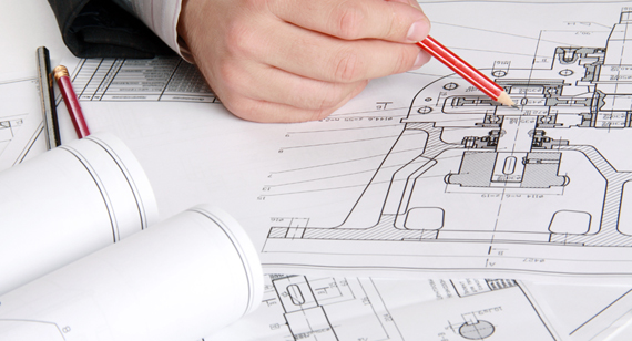
Anyone who is engaged in CNC machining and manufacturing industry starts by drawing the simplest CNC machining parts diagram! The following is an introduction by VMT. From the perspective of mechanical processing and manufacturing, how to cultivate design capabilities and how to draw a good drawing of CNC machining parts?
For example, surveying and mapping a simple CNC machined part, helping others to disassemble and draw the part drawing from the component drawing, etc. These are all stages that a novice must go through. However, even a simple CNC machining part drawing is full of errors: or the dimensioning of the CNC machining vertical parts is incomplete, or the tolerance labeling is inappropriate, or there is a closed dimension chain, or the technical requirements are incorrect, etc. Therefore, the machinery manufacturing industry has always required a long period of accumulation and learning. The foundation is very important, let's start by drawing a drawing of CNC machining parts!
The drawing that expresses the part is called the CNC machining part drawing. It is the basis for the manufacture and inspection of CNC machined parts, the basis for the production of process routes by the process department, and the basis for the inspection by the quality inspection department.
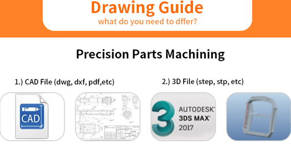
1) Contents of CNC Machining Parts Drawing
The first thing you should know is what should be included in a complete CNC machining part drawing.
1. Graphics: Use a set of views (including views, sectional views, cross-sectional views, etc.) to fully, clearly and simply express the structural shape of the CNC machined part.
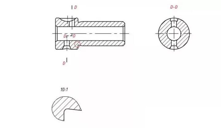
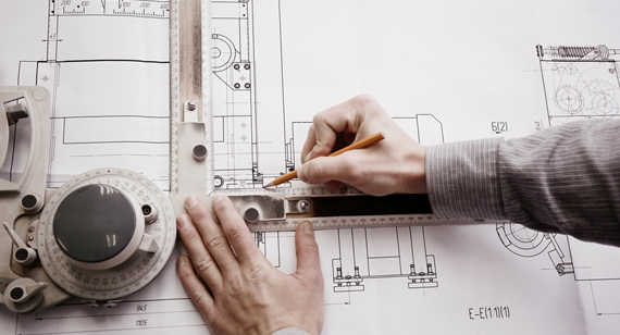
2. Dimensions: Use a set of dimensions to completely, clearly and reasonably mark the structural shape of the parts and the size of their mutual positions.
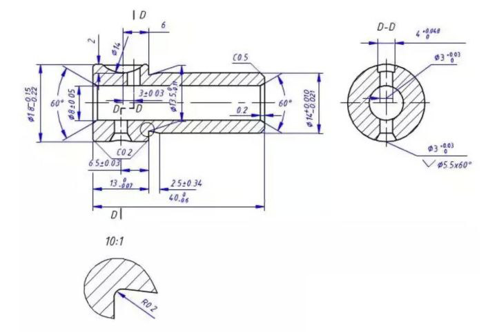
3. Technical requirements: Use some prescribed symbols and words to concisely give the technical requirements that the parts should meet during manufacture, inspection and use. Including roughness, dimensional tolerances, geometric tolerances, datum symbols, technical requirements, etc.
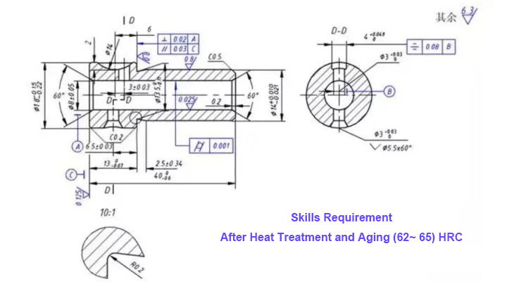
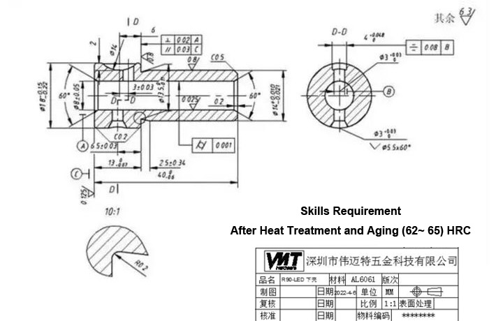
4. Title bar: Use the title bar to fill in the name of the part, the material, the scale of the drawing, the name and date of the drafter and the checker, etc. (The title bar used in this drawing is a simplified version, and only the full version is used in the project).
2) Part Structure Analysis Method
Anyone in the design industry starts out with imitation. Imitate the appearance of others, learn their design ideas, and continuously accumulate experience. The structural analysis of CNC machining parts is to analyze the function of different structures of parts from the design requirements and process requirements. VMT suggests that you not only need to know what the part looks like (simple mapping), but also know why it is designed this way (design ideas), so that you can improve your design ideas instead of blindly imitating them.
1. From the perspective of design requirements, CNC machined parts can play the functions of support, accommodation, transmission, coordination, connection, installation and positioning in the machine, which is the basis for determining the main structure of CNC machined parts.
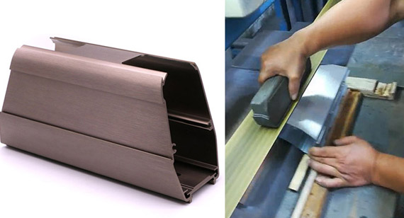
2. From the perspective of process requirements, in order to make the blank manufacturing, processing, measurement, assembly and adjustment of the parts smooth and convenient, structures such as rounded corners, draft angles, and chamfers should be designed. This is the decision of CNC machining parts. basis of local structure.
3. From the perspective of practicality and aesthetics, not only the product is required to be usable, but also economical and aesthetically pleasing, and the structural shape should be considered from the aesthetics point of view.
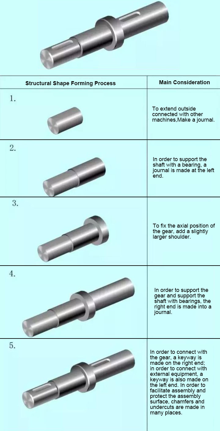
3) Example 1 of Structural Analysis of CNC Machining Parts
The picture below shows the driven shaft of a reducer, which is mainly installed in the bearing, supports the gear to transmit torque, and is connected to external equipment.
We analyze the role of its various features, as well as design ideas.
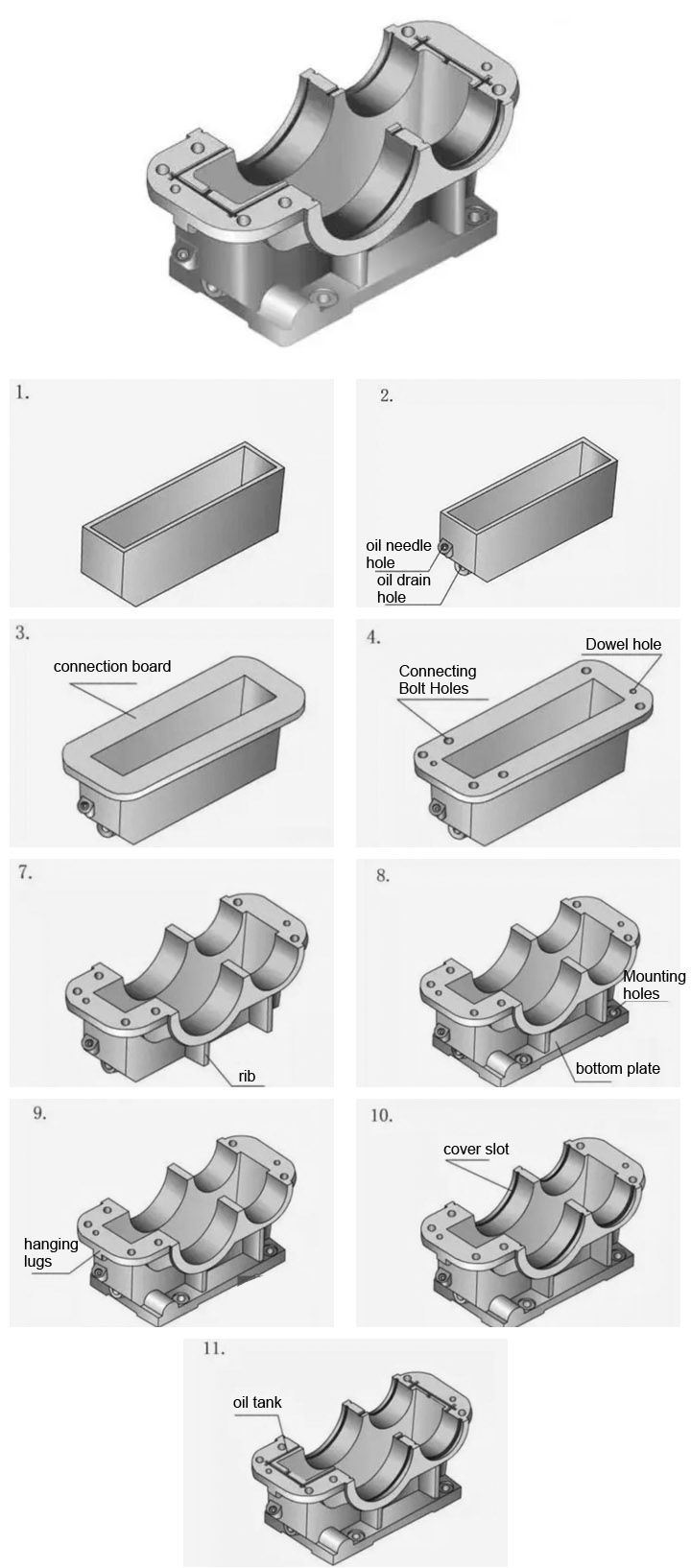
4) Example 2 of Part Structure Analysis
The picture below shows the base of a gearbox, which is a more complex CNC machining part. In the school curriculum design, there must be a design of a reducer. Now analyze the role of each feature of the gearbox base.
In the machinery manufacturing industry, if you want to improve your professional skills quickly after joining the job, following a good professional senior master is definitely the most efficient way, and it is also the best choice for a person to grow. Of course, this requires luck. From my personal experience, at least half of all my professional abilities are due to luck.
The above is a brief introduction of VMT on how to draw a CNC machining part diagram. If you have any questions, please contact us. As a precision CNC machining supplier, VMT provides customers with custom CNC machining parts services and high-precision aluminum parts processing. If you need it, you can contact us immediately and serve you 24 hours a day.

 +86 15099911516


 Read more