16 years one-stop China custom CNC machining parts factory

Hey there I’m VMT Sam!
With 25 years of CNC machining experience we are committed to helping clients overcome 10000 complex part-processing challenges all to contribute to a better life through intelligent manufacturing. Contact us now
 756 |
Published by VMT at Aug 14 2021
756 |
Published by VMT at Aug 14 2021


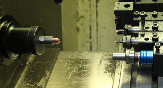
When starting a new project, the best way to communicate is to draw drawings and take photos of samples. For engineers, understanding the basic principles of drawing is the first step of the project. Only in this way can they understand the design intent of CNC machining parts.
Since we can support fast proofing, our customers upload or send documents and drawings to customer service or email to make communication more convenient. Not all technical engineers are senior engineers and can clearly draw the drawings they want. This will increase customer time and communication costs and cause more trouble. We have 10 senior engineers, who can plan the appropriate format, clear drawings and delivery time for you. So VMT has compiled the basic knowledge of drawing technology for everyone.
I hope to help you better understand the basis and importance of drawing of CNC parts. In addition, we will also add hints for you to allow you to do a good job of drawing engineering drawings, so that you can communicate your ideas and designs more clearly, saving time and costs.
What is a CNC part engineering drawing?
When starting a new CNC machining project, the language expression will be unclear. Therefore, we regard engineering product details and technical drawings as the definition standard. Basically, it is a technical document used by engineering circles to accurately express the shape, size and related technical requirements of CNC parts.
Engineering drawing is not only a drawing file used to express, it is a description of technical requirements and manufacturing process. The designer's engineering concept is accurately communicated. Therefore, material specifications, restrictions, acceptable changes, etc. can be drawn in the form of drawings. There are many types of drawings, the most common formats are Stp, DWG and 3DM.
Why draw the drawings?
According to the above description, we draw drawings to better understand the name, tolerance, size, part number and surface treatment process requirements of CNC parts drawings. Convenient and quick production and waste time cost.
How to draw CNC parts drawings?
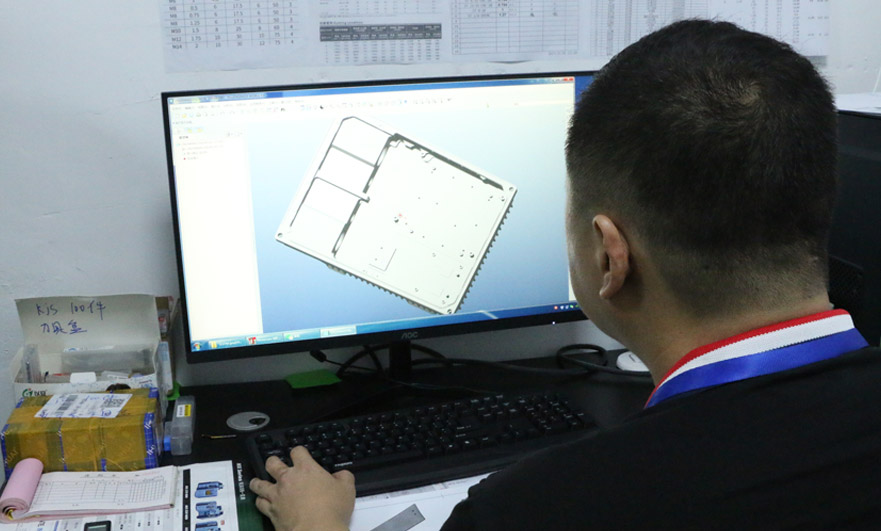
In the age when computers were not popular, people often used drawing boards, rulers, protractors, calipers, etc., which were called hand-drawn engineering drawings. Drawing in this way usually takes longer and is prone to errors. Therefore, as the times change, in order to draw CNC parts engineering drawings more quickly and accurately, we have entered the era of information drawing. The advent of computer-aided design (CAD) software has made things easier.
Compared with manual drawing, this software has many advantages. So can we start from scratch through CAD? drafting paper. In order to describe our CNC parts more intuitively, we can make a 3D model and adjust and modify the size according to the 3D model. Compared with CAD programs, 3D models will be easier to update drawings for modification.
What are the components of the drawing?
Creating drawings of CNC parts to optimize the production process requires a basic understanding of technical drawings. The element composition of drawings can basically be divided into lines, views, isometric views, cross-sectional views, orthogonal views, detailed views, auxiliary views, aspects and information blocks.
Precautions for Engineering Drawing
1. The place to pay attention to is the line type. We know some contour lines or visible transition lines. We use thick solid lines. We use thin solid lines as the dividing line between the dimension line and the polished line. Must be distinguished when applying;
2. For some special tags, you must remember to add a prefix. If they do not have these prefixes, the meaning will be different. For example, add m before the thread and Φ before the circle;
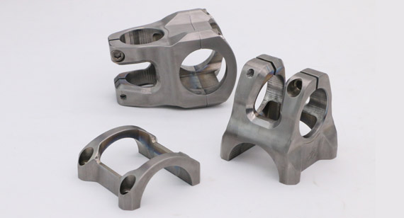
3. The layout of the views we use should be reasonable, not too compact or too loose, as shown in the figure, here we use three general views to represent a connection;
4. For symmetrical CNC part graphics, a center line must be added. In many cases, when drawing graphics, they often forget to add the center line, which means it is different;
5. Don't forget to write technical conditions other than graphics in the upper right corner, as well as the surface roughness requirements of CNC parts, these small details must be paid attention to;
6. The content of the title bar must be filled in completely, especially the proportional relationship must be written correctly.
Pay attention to the relationship between scale and size
Summarize
The drawing of engineering drawings is an important aspect of an engineer's work. Because 20% of the design work time is on drawings. This helps to accurately express the shape, size and processing requirements of CNC parts. During production, it helps to ensure that the manufacturer of CNC machined parts can manufacture in accordance with your drawings.

 +86 15099911516


 Read more