16 years one-stop China custom CNC machining parts factory

Hey there I’m VMT Sam!
With 25 years of CNC machining experience we are committed to helping clients overcome 10000 complex part-processing challenges all to contribute to a better life through intelligent manufacturing. Contact us now
 118 |
Published by VMT at Nov 03 2026 | Reading Time:About 8 minutes


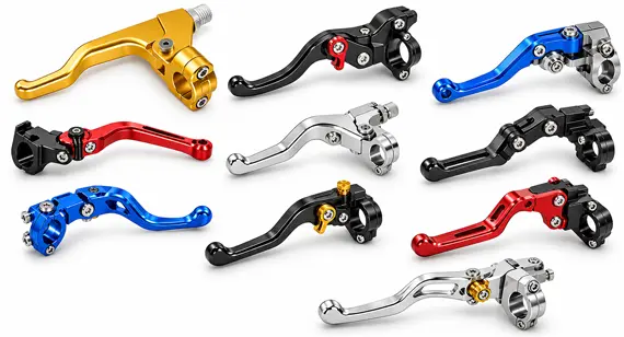
When developing custom CNC motorcycle brake and clutch levers, the key is not simply to achieve the desired appearance or lightweight structure. It is equally important to ensure accurate geometric relationships and reliable assembly fits in critical functional areas, such as pivot holes, bearing seats, and actuation contact surfaces, while considering material properties, surface finishing, and manufacturability for batch production.
Although relatively small, motorcycle levers directly affect rider control, assembly precision, and operational safety. Compared with standard levers, CNC machining offers greater design flexibility in lever geometry, pivot structures, adjustment mechanisms, materials, and surface finishes, supporting different street, off-road, and racing applications.
This article also features a project for a US motorcycle parts manufacturer that required 2,500 custom 6061-T6 aluminum folding levers with smooth R-radius profiles and tight bearing press fits. By adopting an extrusion + CNC finishing process and coordinating engineering and production requirements in advance, our on-demand manufacturing team achieved an 18% reduction in machining costs and completed delivery within 7 days.
CNC motorcycle brake and clutch lever designs differ in lever length, pivot structure, actuation method, and adjustment mechanisms. Therefore, it is important to first identify the lever design, mounting method, and actual operating environment.
Common types of CNC motorcycle brake and clutch levers include the following.
CNC Front Brake Lever Blades
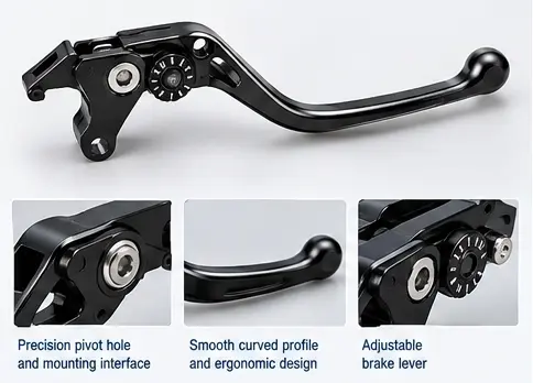
The front brake lever is an important operating component of a motorcycle's braking system. Its design should take into account the pivot hole position, lever length, master cylinder actuation contact point, and installation clearance around adjacent components. The lever should not be designed based on its external shape alone.
| Design Consideration | Recommended Key Parameters |
| 1. Pivot Hole Position | Diameter: Ø6.00 mm or Ø8.00 mm Tolerance: +0.015 / -0.000 mm |
| 2. Lever Length | Long version: 160–175 mm Short version: 135–145 mm |
| 3. Master Cylinder Contact Geometry | Pivot-to-contact center distance: 18.00 mm or 20.00 mm Contact surface: Convex arc, R5.0–R8.0 mm |
| 4. Clearance Around Adjacent Components | Handlebar clearance: ≥ 10 mm Handguard clearance: ≥ 15 mm |
Note: The dimensional values listed above are preliminary engineering reference recommendations. Actual dimensions and tolerances should be determined based on component geometry, mating interfaces, assembly requirements, and applicable engineering practices. For general dimensioning and geometric tolerancing principles, refer to ISO 286-1.
CNC Clutch Lever Blades
Custom CNC clutch levers are primarily used to operate the clutch release mechanism. Common designs include cable-operated and hydraulic clutch levers.
Cable-operated clutch levers need to accommodate the cable retaining slot, cable barrel position, adjustment nut, and cable movement clearance. Hydraulic clutch levers, on the other hand, require the pushrod contact position and movement geometry to be determined according to the specific system.
These functional interfaces directly affect lever geometry and machining accuracy.
| Clutch Type | Key Design Area | Recommended Key Parameters |
| Cable Type | Cable Barrel Slot | Diameter: Ø8.10–Ø8.5 mm Depth: 9.50–10.50 mm |
| Cable Wire Slot | Slot width: 2.50–3.00 mm | |
| Cable Path | Swing clearance angle: ≥ 15° | |
| Hydraulic Type | Master Cylinder Actuation Geometry (Leverage Ratio) | Pivot-to-pushrod contact distance: 16.00–18.00 mm |
| Pushrod Contact Geometry | Convex contact surface: R5.0–R8.0 mm Alternatively, a locating blind hole, depending on the system |
Note: These specifications have been compiled with reference to common Japanese cable-operated systems and hydraulic systems from manufacturers such as Brembo and Magura. They are intended for design reference only.
Foldable Brake & Clutch Levers
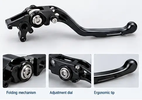
CNC foldable levers typically use a separate pivot, spring, or other return mechanism to allow the lever to fold in a specific direction for different application requirements.
Key design considerations include:
For off-road applications where drops or impacts are more likely, structural and functional validation should also be performed based on the expected loads. The addition of a folding mechanism alone does not guarantee impact resistance.
| Design Consideration | Recommended Key Parameters |
| 1. Folding Pivot Pin Fit | Pivot pin diameter: Ø5.0–Ø6.0 mm Fit tolerance: H7/h6, close fit |
| 2. Extended Positioning Structure (Ball Detent) | Steel ball size: Ø4.0 mm or Ø5.0 mm Built-in high-resilience positioning spring |
| 3. Stopper Interface | Contact area: ≥ 50 mm² Structure: Stepped or dovetail-style hard stop |
| 4. Return Spring Space | Spring groove depth: 12–15 mm Clearance allowance: 0.5 mm on one side |
| 5. Running and Pinch-Prevention Clearance | Rotational clearance: 0.15–0.25 mm Load-bearing section thickness: ≥ 10 mm |
Note: These values are for reference and are intended to minimize the risk of insufficient stopper-face strength or an excessively loose pivot-pin fit.
CNC Off-Road & Dirt Bike Levers
CNC off-road and dirt bike levers must accommodate demanding operating conditions, including mud, sand, vibration, impact, and frequent operation.
Depending on the application, the design can incorporate folding mechanisms, optimized cross-sections, mud-clearance features, and corrosion-resistant surface treatments. Weight can also be reduced through appropriately designed grooves and material removal while maintaining the required structural integrity.
| Key Design Area | Recommended Custom Machining Specifications | Application Purpose |
| 1. Cross-Section and Break Point | Root thickness: ≥ 12 mm Add an R1.5–R2.0 mm breakaway groove at the outermost one-third of the lever |
Designed to fold or bend without completely breaking |
| 2. Mud Clearance | Increase pivot/folding joint clearance to 0.3–0.4 mm Machine a 1.5 mm through-channel inside the pivot shaft for mud drainage |
Prevents mud and sand from jamming the mechanism |
| 3. Lightweight Structure and Grip Texture | Add I-beam-style relief pockets to non-load-bearing areas Machine transverse anti-slip grooves on the gripping surface to a depth of 0.5 mm |
Balances structural strength and grip |
| 4. Surface Finish | Hard anodizing Coating thickness: ≥ 30 μm |
Helps resist gravel and stone impacts |
| 5. Anti-Vibration and Fastener Retention | Reserve a Ø1.5 mm safety-wire hole in the fastener Alternatively, apply medium- or high-strength threadlocker during assembly |
Helps prevent loosening under high-frequency vibration |
CNC Short & Long Levers
Lever length affects grip position, operating leverage, and installation clearance.
Short levers are generally suitable for compact designs and riders who prefer two- to three-finger operation, with typical lengths of 135–145 mm.
Long levers provide a wider hand contact area and are generally suitable for four-finger or full-palm operation, with typical lengths of 160–175 mm.
CNC Lightweight Racing Clutch Levers
Racing levers often have higher requirements for weight, structural rigidity, and operating geometry.
You can reduce unnecessary material by optimizing the cross-section, adjusting local wall thicknesses, and incorporating weight-reduction pockets. However, stress concentration, machining deformation, and structural strength validation must also be taken into account.
CNC Length-Adjustable Levers
Length-adjustable levers typically use sliding structures or adjustment mechanisms to change the rider's grip position.
In addition to controlling the basic dimensions, the following factors should also be considered:
For most CNC aluminum motorcycle lever projects, 6061-T6 and 7075-T6 are two materials worth comparing.
For example, 6061-T6 can be a preferred option for conventional street motorcycle levers. For designs with greater sensitivity to weight and strength, 7075-T6 aluminum or titanium alloys can also be considered.
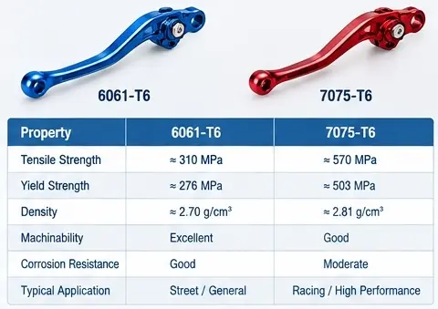
For off-road applications, expected impact loads, structural fatigue, and corrosion exposure should be taken into account. Racing applications require a balance between weight, structural rigidity, and actual operating requirements.
Ultimately, material selection should be based on the product drawings, load conditions, structural validation, and budget rather than assuming that one material is suitable for every motorcycle lever.
Selecting Materials Based on Operating Environment and Functional Requirements
You can evaluate the following factors when selecting materials for CNC motorcycle brake and clutch levers:
| Selection Factor | Specific Requirements or Application | Recommended Material | Reason for Recommendation |
| Operating Environment | Street motorcycles | 6061-T6 Aluminum | Offers a balanced combination of machinability, strength, and corrosion resistance for conventional custom levers |
| Off-road / Dirt bikes | 6061-T6 or 7075-T6 Aluminum | Material can be selected according to expected impact loads and structural requirements, with particular attention to impact-resistant design and validation | |
| Racing motorcycles | 7075-T6 Aluminum or Ti-6Al-4V Titanium | Suitable for designs requiring a higher strength-to-weight ratio and lightweight construction | |
| Weight and Structural Strength | Standard strength with a balance of weight and cost | 6061-T6 Aluminum | Offers balanced overall properties and is suitable for many conventional custom projects |
| High strength and lightweight requirements | 7075-T6 Aluminum | Provides a high strength-to-weight ratio for high-performance structures | |
| Specialized high-strength, lightweight, and corrosion-resistant requirements | Ti-6Al-4V (Grade 5) Titanium | Offers a high strength-to-weight ratio, although material and CNC machining costs are higher | |
| Structural Function | Fixed levers without complex moving mechanisms | 6061-T6 or 7075-T6 Aluminum | Selection depends on strength, weight, and cost requirements |
| Folding levers | 6061-T6 or 7075-T6 Aluminum; 17-4PH stainless steel pivot pins | Aluminum is used for the lever body, while stainless steel can be used for wear-resistant connection components such as pivot pins | |
| Sliding or length-adjustable levers | 6061-T6 or 7075-T6 Aluminum; 303 or 304 stainless steel | The main body and auxiliary components can be selected according to sliding-interface fit, wear, and load requirements | |
| Surface Treatment | Colored anodizing (black, red, gold, blue, etc.) | 6061-T6, 6063, or 7075-T6 Aluminum | Suitable for aluminum anodizing, subject to confirmation of final color and consistency based on the alloy and process |
| Hard anodizing | 6061-T6 or 7075-T6 Aluminum | Suitable for designs requiring higher surface hardness and wear resistance; coating effects on mating dimensions must be considered | |
| Special coatings such as PVD and DLC | Stainless steel, titanium, and aluminum substrates validated for the coating process | Selection depends on coating compatibility, substrate, and functional requirements | |
| Nickel plating, chrome plating, or other metallic finishes | Suitable stainless steel or aluminum substrates | Selection depends on coating adhesion, corrosion resistance, and final dimensional requirements | |
| Production Quantity and Manufacturing Route | Prototyping and design validation | Solid 6061-T6 or 7075-T6 aluminum billet | Avoids the need for an initial extrusion die investment and makes design modifications easier |
| Small-batch custom production | 6061-T6 or 7075-T6 Aluminum | The CNC machining route can be selected according to part geometry, material utilization, and machining time | |
| Large-volume production and long-term repeat orders | 6061-T6 or 6063 extruded profiles + CNC finishing | When the part cross-section is suitable for extrusion, this route can reduce machining allowances and improve material utilization | |
| Specialized high-performance batch projects | 7075-T6 Aluminum or Titanium | Final selection should consider order quantity, material cost, machining capabilities, and performance validation requirements |
As discussed in the material selection section, surface treatment is also an important consideration when selecting materials. In addition to the treatments already mentioned, several other finishes and combinations are available to meet different appearance and tactile requirements:
Dimensional Design: How Does Surface Finishing Affect Bearing and Pivot Fits?
This is an easily overlooked detail in CNC motorcycle lever manufacturing.
For example, if a bearing needs to be press-fitted into the lever body, checking the bearing bore only after CNC machining while ignoring the subsequent anodizing or other coating processes may result in a final bore diameter that does not meet the required fit.
The following table provides practical recommendations for understanding how surface finishing affects critical mating dimensions on CNC motorcycle levers.
| Component Area | Common Surface Treatment | Recommended Processing and Dimensional Control |
| Bearing Press-Fit Bore | Hard anodizing (Type III) | To maintain a precision press fit, masking the bearing bore is generally recommended to prevent the oxide layer from affecting the bore diameter. If the bore itself also requires hard anodizing, use a 25 μm coating thickness as a calculation example and allow approximately 25 μm of diametral compensation. Inspect the final dimensions after anodizing. |
| Pivot Bore | Hard anodizing or standard anodizing | For pivot bores with strict dimensional accuracy and rotational-fit requirements, select masking or dimensional compensation according to the functional requirements. If the anodized layer must be retained, calculate the machining dimensions backward from the required final bore diameter, then inspect the bore after finishing using an internal measuring instrument or dedicated gauge. |
| Threaded Holes | Anodizing or hard anodizing | Mask precision threaded holes where necessary to prevent the anodized layer from affecting thread engagement and effective dimensions. Use thread plug gauges after finishing. If post-finishing tapping is selected, note that it will remove the coating locally. |
| Sliding Interfaces and Adjustment Slots | Hard anodizing | Allow for coating growth in the sliding clearance to prevent binding after finishing. For example, with a 25 μm coating, each surface may experience approximately 12.5 μm of outward dimensional growth. Calculate the final clearance based on the actual treatment of both mating surfaces. |
| Bearing Faces and Datum Surfaces | Anodizing or hard anodizing | If flatness, mounting height, or axial clearance requirements are strict, local masking is recommended. If these surfaces are treated, include coating thickness in the dimensional stack-up and perform post-treatment inspection. |
| Lever Cosmetic Surfaces and Radii | Bead blasting + anodizing or hard anodizing | Allow for the specified coating thickness during machining. For example, with a 25 μm coating, two opposing external surfaces may each grow outward by approximately 12.5 μm, increasing the overall dimension by approximately 25 μm. Avoid sharp edges and use appropriate radii to improve coating uniformity. |
| Pivot Pins and Moving Components | Hard anodizing or other wear-resistant treatments | Aluminum contact surfaces can be treated according to wear-resistance requirements. Steel pivot pins and other non-aluminum components should be evaluated separately to prevent unsuitable components from being exposed directly to the anodizing process. |
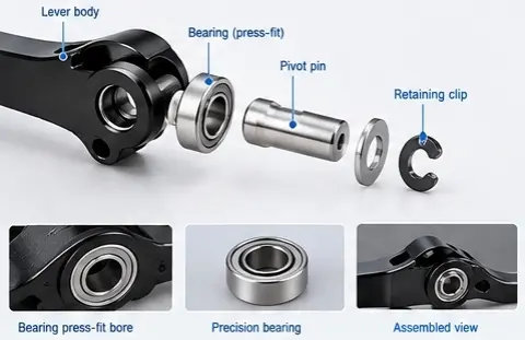
CNC-machined motorcycle brake and clutch levers have numerous exposed surfaces, curved R-radius profiles, and hand-contact edges. Consistent curve transitions, edge finishing, and surface textures are therefore essential to achieving the desired appearance and comfortable ergonomics.
| Inspection Area | Common Design Issues | DFM Recommendations |
| Surface Transitions | Abrupt transitions between different surfaces, visible lines, uneven areas, or unnatural seams | Use tangent-continuous surface transitions (G1) in the 3D model. For areas with higher cosmetic requirements, consider curvature continuity (G2) and avoid joining multiple small, discontinuous arcs. |
| Radii and Curved Profiles | Inconsistent R-radius dimensions or asymmetrical local curves that result in an uneven appearance | Specify critical R-radius dimensions and profile tolerances in the 2D drawing. Keep adjacent radii consistent where possible. Use suitable ball-end cutters or contour machining toolpaths, and verify the actual geometry through profile inspection. |
| Lever Edges and Chamfers | Excessively sharp edges, burrs, sharp corners, or inconsistent chamfers | For non-functional edges, consider C0.2–0.5 mm chamfers or suitable radii according to grip requirements as an initial design reference. Avoid sharp edges in hand-contact areas. Do not apply arbitrary chamfers to bearing holes, pivot holes, or locating surfaces, as this may affect assembly. |
| CNC Tool Marks and Surface Scratches | Visible tool marks, toolpath transition marks, scratches, or localized machining traces on cosmetic surfaces | Plan dedicated finishing toolpaths for cosmetic surfaces and keep tool movement and cutting directions consistent where possible. Minimize unnecessary re-clamping, and specify surface roughness requirements or sample-based acceptance criteria for visible surfaces. |
| Blasting and Anodizing Consistency | Uneven blasting textures, color variation, or inconsistent gloss levels within the same production batch | Standardize the blasting media, grit size, and process parameters. Confirm the alloy and surface preparation requirements before anodizing. Use approved color samples for reference and maintain consistent finishing conditions throughout the batch. |
| Logo and Laser Marking | Misaligned logos, unclear lines, or marking effects that do not meet expectations after anodizing | Specify the logo position, size, and orientation from clearly defined drawing datums. Decide in advance whether the logo should be engraved before anodizing or laser-marked after finishing. Produce samples to confirm the font, line width, depth, and final contrast. |
There are two common manufacturing routes for CNC motorcycle brake and clutch levers. One involves machining directly from solid aluminum billets, while the other uses extrusion to produce a near-net-shape blank, followed by CNC finishing.
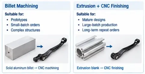
Choosing the More Cost-Effective CNC Motorcycle Lever Manufacturing Route
Option 1: Prototyping, Small-Batch Orders, or Complex Structures — Prioritize Solid Billet CNC Machining.
Solid billet CNC machining is generally more suitable when order quantities are small, product designs are still being validated, or the lever has complex three-dimensional surfaces, significant cross-section variations, or irregular pockets.
This is because solid billet machining typically does not require additional extrusion die investment or waiting for dedicated profile development. For smaller orders (a recommended reference range of 1–3,000 pieces), it can avoid increasing unit costs by spreading die expenses across a limited number of parts. It also makes subsequent design modifications easier.
Option 2: Mature Designs, Large-Batch Production, or Long-Term Repeat Orders — Prioritize Evaluating Extrusion + CNC Finishing (Usually Aluminum).
When a motorcycle lever has a relatively consistent main-body cross-section and its basic profile can be formed through extrusion, the extrusion + CNC finishing route is generally more favorable for reducing batch production costs.
For example, if the lever body has a long and relatively uniform cross-section, an aluminum extrusion can first produce a blank close to the final part shape. CNC machining can then complete precision features such as pivot holes, bearing seats, adjustment slots, and other functional interfaces.
When order quantities are sufficiently large (a recommended reference quantity of 5,000 pieces or more), or when repeat orders are expected, the initial extrusion die investment can be distributed across more parts, helping reduce the overall unit manufacturing cost.
Our engineering team adopted an extrusion + CNC finishing process and completed 2,500 custom 6061-T6 CNC folding motorcycle brake and clutch levers, achieved an 18% reduction in machining costs, and delivered the order within 7 days.
A US motorcycle parts manufacturer planned to order 2,500 custom 6061-T6 aluminum folding brake and clutch levers. The customer provided 3D design files and specified an overall lever length of approximately 155 mm, a smooth curved profile in the gripping area, consistent R6–R8 external radii, and edges without noticeable sharp corners. For the appearance, the customer requested fine bead blasting followed by matte black anodizing to achieve a uniform, deep black metallic finish, with the brand logo laser-marked on the lever surface. For dimensions, general machining tolerances were required to be within ±0.05 mm, while the bearing mounting holes and pivot holes required separately specified precision tolerances of ±0.01 mm based on the actual assembly requirements.
The project involved two main challenges. First, the lever body had a relatively long curved outer profile, and the multiple R-radius transitions needed to remain smooth and natural. Visible toolpath transition marks, asymmetrical local curves, and uneven surface textures after blasting had to be avoided. Second, the bearings needed to be press-fitted into the lever bodies, making it essential to control the bearing bore diameter, roundness, and positional relationships. During the initial engineering evaluation, a bearing bore roundness target of 0.01 mm was considered. The final fit tolerance was to be determined based on the actual bearing outside diameter, bore diameter, and required interference. At the same time, the black anodized coating could affect mating dimensions, so masking solutions for the bearing bores and other precision interfaces had to be planned in advance.
Based on the order quantity of 2,500 pieces and the part geometry, our on-demand manufacturing engineering team selected a 6061-T6 aluminum extrusion + CNC finishing route. The extruded blank was designed to approximate the main lever-body profile, reducing the amount of material removal required. CNC machining was then used to complete the curved outer profile, R-radius features, bearing seats, pivot holes, and folding connection structures. During machining, general external dimensions were controlled according to the ±0.05 mm reference tolerance, while the bearing bores underwent dedicated dimensional inspections to verify the required fit. Surface finishing consisted of fine bead blasting followed by Type II black anodizing, with a reference coating thickness of 10–15 μm. The bearing bores, pivot mating surfaces, and threaded holes were masked as required by their functional requirements to prevent the coating from affecting final assembly dimensions. The laser logo was applied after anodizing to maintain clear markings and brand identification.
Ultimately, the project completed all 2,500 6061-T6 aluminum folding brake and clutch levers. Compared with the previously evaluated approach of machining entirely from solid aluminum billets, the extrusion + CNC finishing route reduced the amount of material removed from the main body and shortened some rough-machining operations, resulting in an approximately 18% reduction in machining costs. The 7-day production and delivery period started after final drawing and process approval, with materials and production conditions ready, and did not include international transportation. By controlling the curved profiles, bearing mating dimensions, and surface treatment areas separately, the project met the customer's requirements for consistent appearance, ±0.01 mm critical-interface assembly tolerances, and rapid batch delivery.
A reliable CNC motorcycle brake and clutch lever requires more than a refined external profile. It also depends on appropriate material selection, accurate pivot geometry, reliable bearing fits, and suitable surface finishing processes. For custom motorcycle control component development, conducting a DFM review early, defining functional mating dimensions, and selecting the right CNC machining route based on production quantity can help reduce manufacturing difficulties, control production costs, and improve consistency in batch production.
Are you developing custom CNC motorcycle brake levers, clutch levers, or other components but are facing challenges with bearing fit control, bore dimensional changes after anodizing, or choosing between solid billet and extrusion machining routes? Send your drawings to our engineering team, and we can evaluate critical dimensions, tolerance and fit requirements, DFM manufacturability, and machining costs, and provide a suitable manufacturing solution and quotation.
Send your 2D drawings, 3D CAD models, material, lever type, pivot and bearing requirements, tolerance requirements, surface finish, prototype quantity and production quantity. VMT will review DFM, material selection, solid billet or extrusion + CNC routing, critical fits, surface-treatment allowances, inspection and quotation requirements.
All information and uploaded files are secure and confidential.
1 Tell us what you need
2 Get solution & quote
3 Approve production
Email: inquiry@vimetal.com.cn
Q1: Which Aluminum Alloy Is Best for CNC Motorcycle Brake Levers?
6061-T6 and 7075-T6 are two aluminum alloys worth considering.
6061-T6 offers a balanced combination of machinability, strength, and corrosion resistance, making it suitable for many conventional custom projects. 7075-T6 provides a higher strength-to-weight ratio and can be used for designs with more demanding structural strength and lightweight requirements.
However, the final material selection should be based on the product structure, actual loading conditions, surface finishing requirements, and cost.
Q2: Does Anodizing Affect Bearing Fits on Motorcycle Levers?
Yes.Anodizing changes the final surface dimensions of aluminum components. Therefore, the dimensional effects of the oxide layer must be considered in advance for bearing seats, pivot holes, and other precision mating areas.
Depending on the specific design, the engineering team can select dimensional compensation, local masking, or other suitable processing methods, followed by inspection of the final dimensions after surface finishing.
Q3: What Requirements Should Be Specified in Custom CNC Motorcycle Lever Drawings?
Custom CNC motorcycle lever engineering drawings should ideally include the material grade, critical dimensions, tolerances, mating requirements, surface finish, logo position, and any special technical requirements.
If the component involves press-fit bearings, folding mechanisms, or length-adjustment structures, the corresponding assembly and functional requirements should also be clearly specified to support the manufacturer's DFM review.
Q4: How Does Your Factory Reduce CNC Motorcycle Lever Machining Costs?
Based on your drawings and specific application environment, we can optimize the following areas or provide corresponding DFM recommendations:
These design adjustments can help reduce unnecessary machining operations, material waste, and rework risks.
Q5: Can CNC Motorcycle Levers Achieve a Machining Tolerance of ±0.005 mm?
This is a relatively tight tolerance requirement.
For certain critical machined features with appropriate design and process conditions, high-precision machining to ±0.005 mm can be evaluated based on the drawing requirements.
However, ±0.005 mm should not be treated as a universal machining tolerance for every lever dimension, every hole, or dimensions after surface finishing. For functional interfaces such as bearing holes and pivot holes, the achievable dimensions and inspection standards should be confirmed separately during the project review.
Q6: How Do You Ensure the Quality of CNC Motorcycle Levers?
Quality control needs to cover the entire manufacturing process rather than focusing solely on final cosmetic inspection.
We manage quality through the following stages:
For safety-related brake and clutch components, appropriate structural and functional validation is also carried out according to the product application and applicable requirements.


 +86 15099911516




 Read more