16 years one-stop China custom CNC machining parts factory

Hey there I’m VMT Sam!
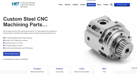
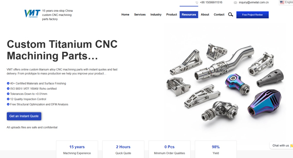
With 25 years of CNC machining experience we are committed to helping clients overcome 10000 complex part-processing challenges all to contribute to a better life through intelligent manufacturing. Contact us now
 71 |
Published by VMT at May 24 2026 | Reading Time:About 4 minutes
71 |
Published by VMT at May 24 2026 | Reading Time:About 4 minutes


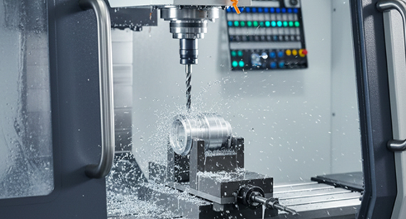
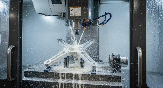
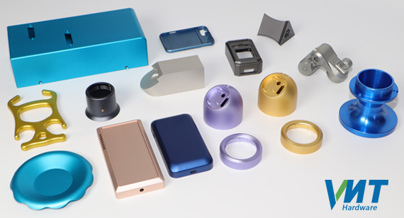
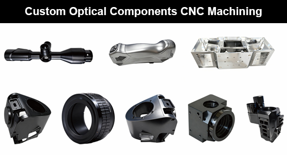
Camera lenses—from smartphone modules to professional cinema optics—depend on precisely engineered mechanical components to achieve optical performance. Lens barrels, mounts, aperture mechanisms, and optical stands, each require micron-level precision to maintain alignment, ensure smooth focusing, and deliver sharp images.
It is surely you can design the perfect camera lens parts when sitting in the office. But when the custom parts' drawings were delivered to the CNC machining factory, something wrong could happen. Due to the out-of-concentricity of the lens barrel or clamping deformation of thin-walled parts, lenses may suffer from slight decenter or tilt after assembly, leading to blurry edges and astigmatism in your final products.
Additionally, you need to pay attention to more camera lens parts manufacturing issues—Does the outdoor temperature difference matter, even if the lens parts perform perfectly in a constant temperature laboratory. If the surface treatment is improper (such as substandard anti-reflective anodizing), it generates internal stray light, does it affect the performance? Did your supplier conduct precise inspections like CMM (Coordinate Measuring Machine) before shipping to ensure the tolerances are met? And so on.
This guide covers the design considerations, materials, manufacturing processes, and quality requirements for camera lens precision components, providing you with a comprehensive understanding of camera lens parts manufacturing and helping you avoid common pitfalls.
1.1 Camera Lens Types, Key Components, and Application Market
Different imaging applications dictate completely different manufacturing complexities and hardware requirements. The table below outlines the core components based on lens types:
| Lens Type |
For Which Product? |
Critical Components |
Application Market |
| Smartphone Lenses |
Phones, Tablets | Miniature Voice Coil Actuators (VCM), Plastic or metal barrels | Consumer Electronics |
| DSLR/Mirrorless Lenses |
Professional Photography | Metal barrels, Auto-focus motors, Image stabilization units | Professional Photography |
| Cinema Lenses |
Movie Production | Precision gear drives, T-mounts, Manual focus mechanisms | Cinema & Broadcast |
| Surveillance Lenses |
Security, Monitoring | Waterproof seals, IR-corrected optics | Security & Infrastructure |
| Medical Endoscopes |
Endoscopes, Microscopes | Miniature housings, Biocompatible materials | Medical & Life Sciences |
| Industrial Vision |
Machine Vision, Inspection | High-precision chassis, Repeatable positioning mounts | Industrial Automation |
| Automotive Lenses |
ADAS, Dashcams | Ruggedized housings, Temperature-stable mounts | Automotive |
1.2 Camera Lens Component Architecture

To achieve optimal optical alignment, well-performed camera lens rely on a complex, multi-layered mechanical structure. Here is the clear breakdown of custom CNC camera lens components:
Camera Lens Components Architecture Includes:
Lens Barrel Assembly

Optical Element Holders & Support
Aperture & Iris System
Focusing Mechanisms
Image Stabilization (IS) System
Lens Mount Components
Accessories & Fittings
2. Engineering Design Requirements and Critical Tolerances for Camera Lens Parts
2.1 Optical Alignment Requirements
When multiple lens elements are housed within a metal structure, a deviation of just a few microns can cause asymmetric astigmatism, edge-to-edge sharpness to collapse, or local blurring. It’s important for you to learn about these following alignment boundaries, so as to ask your suppliers to manufacture precision lens parts with these tolerances.
2.2 Interface Tolerances for Crucial and Non-crucial Surface
Although it's important for key surface with an ultra-tight ±5μm tolerance, some other not-so-necessary surface don' t need this ultra-tight tolerance. Understanding this difference can help you save much machining cost. Here' s a clear table for your reference:
| Interface |
Tolerance |
Insight |
| Barrel ID (lens fit) |
±5μm | Element centering: This is the critical lens fit area. It must be ultra-tight to ensure flawless lens element alignment without pinching or crushing the glass. |
| Helicoid thread |
±0.01mm | Smooth focus travel: Controls the multi-start thread engagement. Tight lead control eliminates focus play, backlash, and tactile "grittiness." |
| Mount register |
±0.01mm | Flange focal distance: Secures the exact register distance to the sensor. If this exceeds the limit, the lens will fail to focus at infinity. |
| Filter thread |
±0.02mm | Accessory compatibility: Ensures easy accessory attachment, allowing standard filters to thread on smoothly without binding or seizing. |
| Blade pivot |
±0.02mm | Smooth iris operation: Ensures smooth aperture blade movement and precise positioning for consistent exposure control. |
2.3 Best Design Tips for Specific Environmental Requirements
You surely don't want the camera lens parts performs well in a mild indoor uses but performs poorly when in a changed environment like a vibrating drone, or a freezing outdoor. So, please pay attention to these tips to avoid pitfalls:
| Environment |
Requirement |
Design Tips |
| Temperature |
-40℃to +85℃ (auto) | Material selection & thermal management: For example, due to CTE mismatches between aluminum(len parts) and glass(lens), please calculate precise expansion gaps to prevent image blur or glass cracking. |
| Humidity |
0-95% RH | Sealed bearings & hydrophobic greases: Utilizing specialized O-ring grooves and moisture-barrier damping greases to lock out water vapor. |
| Vibration |
MIL-STD-810G (auto) | Damped mounts & locked mechanisms: Implementing thread-locking structures and spring preload mechanisms to prevent optical shift under harsh vibration. |
| Dust / Moisture |
IP64+ (surveillance) | Gasket seals & protected mechanics: Precision machining of custom gasket profiles and sealing steps for outdoor weatherproofing. |
| Shock | 1000g (consumer) | Spring mounts & impact absorption: Designing ruggedized internal shock-absorbing component interfaces to withstand accidental drops. |
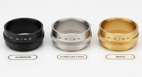
3.1 Lens Barrel Materials ( Example of Camera Lens Parts)
Because there are so many precision parts for camera lens, here I just take the most typical “ Lens Barrels” as the example:
| Material |
Properties |
Applications |
Trade-offs |
| Aluminum 6061 |
Good machinability, anodizable | Standard lens barrels | Cost-effective |
| Aluminum 7075 |
High strength, aerospace | Premium lenses | Higher cost |
| Stainless 303 |
Corrosion resistant | Weather-sealed lenses | Heavier |
| Brass C360 |
Machinable, durable | Filter threads, rings | Lower strength |
| Polycarbonate |
Lightweight, moldable | Consumer lenses | Lower precision |
| Magnesium Alloys |
Ultra-lightweight | Mobile phone lenses | Corrosion concern |
3.2 Optical Element Materials
The following matrix outlines the key properties and applications of common lens element materials— better for you to understand the substrates housed within the CNC components:
| Material |
Properties |
Applications |
| Optical glass |
Borosilicate, crown glass | Lens elements |
| Crystal (quartz, sapphire) |
UV/IR applications | Special optics |
| Germanium |
IR transmission | Thermal imaging |
| Plastic (PMMA, PC) |
Cost, weight | Consumer optics |
3.3 How will You Choose the Suitable Materials?
When determining the optimal material for these optical hardware, follow these below simple rules, or you are welcomed to consult with us:
4.1 Essential Surface Treatments for Camera Lens Parts

These are what you can ask the CNC machining factory to do with your custom lens parts’ surface. The table below outlines the primary surface treatments used for specific lens components:
| Treatment |
Purpose |
Application |
| Black anodizing |
Anti-reflection, light absorption | Interior barrel surfaces |
| Nickel plating |
Corrosion resistance | Brass components |
| Black oxide |
Anti-reflection | Steel components |
| Precision polishing |
Mirror surfaces | Reflective elements |
| Hard anodizing |
Wear resistance | Helicoid threads, sliding surfaces |
4.2 Interior Surface Requirements for Camera Lens Parts
To optimize light control and prevent internal reflections inside the optical chassis, ensure the following specifications are met:
4.3 Mechanical Surface Requirements for Camera Lens Parts
For moving parts and mating interfaces, precise control of surface roughness determines the overall tactile feel and alignment stability of your camera Lens components:
| Surface |
Roughness Requirement |
Purpose |
| Helicoid thread |
Ra 0.2-0.4μm | Smooth focus travel |
| Bearing race |
Ra 0.1-0.2μm | Low friction |
| Mount flange |
Ra 0.4-0.8μm | Flat seating |
| Filter thread |
Ra 0.8μm max | Leak-free seal |
5.1 Precision Machining Overview
The table below specifies the typical manufacturing processes and strict tolerance thresholds required for precision lens components during precision cnc machining:
| Component |
Typical Processes |
Tolerances |
| Lens barrel |
CNC turning, boring | ±5μm |
| Helicoid |
CNC lathe, thread grinding | ±0.01mm |
| Lens mount |
4-axis CNC, milling | ±0.01mm |
| Retaining ring |
CNC turning, threading | ±0.01mm |
| Spacer ring |
CNC turning, lapping | ±0.02mm |
| Filter ring |
CNC turning | ±0.01mm |
5.2 Machining Flow For Lens Parts—Taking The Lens Barrel As The Example
To ensure consistent micron-level precision, standard lens barrel production must follow a strict, multi-stage manufacturing sequence:
5.3 Helicoid Design for Smooth Focus
Achieving a premium tactile feel and zero-backlash motion during manual focusing requires strict control over thread geometry, engineering design, and production methods:
| Category |
Design Specification |
Performance Target |
| Thread Geometry |
Lead accuracy
Pitch variation Surface finish Hardness |
±0.01mm < 5μm Ra 0.2-0.4μm 60+ HRC (Hard anodized) |
| Design for Smoothness |
Multi-start thread Bearing design Lead consistency Lubrication |
2-4 starts for balanced torque Preloaded ball bearing to eliminate backlash Constant lead variation across travel Low-viscosity grease for optical hardware |
| Manufacturing Methods |
Turning + Grinding Precision CNC Machining Forming |
Best method for premium cinema/photography optics Good, reliable method for standard production runs Best suited for high-volume consumer applications |
5.4 Quality Assurance Protocols
Before final delivery, camera lens components are quite necessary to undergo a rigorous series of metrology tests to verify both dimensional adherence and functional smoothness:
| Test Type |
Inspection Method |
Target Quality Standard |
| Dimensional |
CMM (Coordinate Measuring Machine), air gauges | ±5μm |
| Concentricity |
Talyrond roundness tester, coordinate measuring | < 5μm |
| Thread fit |
Go/No-Go thread gauge testing | ±0.01mm |
| Surface finish |
Profilometer scanning | Ra 0.1-0.8μm |
| Helicoid smoothness |
Manual tactility operation check | Smooth movement, no galling |
| Torque measurement |
Digital torque wrench verification | Consistent rotational values |
Implementing optimal and practical Design for Manufacturing (DFM) guidelines can help you optimize the production yield for camera lens parts and prevent unnecessary budget blowouts.
6.1 Top DFM Guidelines
It’s not necessary for all interfaces to use ultra tight tolerance.
6.2 Cost Reduction Strategies
Apply these straightforward production strategies to optimize your procurement budget:
| Strategy |
When to Use |
Budget Savings |
| Tolerance relaxation |
Non-critical mechanical features & exterior walls | 15–25% |
| Batch anodizing |
Ordering multiple parts or assemblies together | 20–30% |
| Thread standardization |
Using common pitches across your lens chassis | 10–20% |
| Die casting + CNC |
High-volume production scales exceeding 5,000 units | 30–50% |
| Material substitution |
Swapping 7075 for 6061 when budget is the primary driver | 15–30% |
High-Precision Professional DSLR Lens Mount

A leading camera manufacturer approached VMT CNC Machining Factory to solve a production bottleneck for their high-end 70-200mm telephoto lens. The project required the mass production of an F-mount compatible lens mount that could maintain a strict register distance of 46.5mm ±0.01mm. Additionally, the design demanded integrated slots for 9 gold-plated data contact points to handle high-speed autofocus transmission, alongside a robust weather-sealed structure to support heavy glass elements during rugged outdoor field use.
To meet these rigorous specifications, we developed a streamlined, multi-step CNC manufacturing workflow utilizing aerospace-grade aluminum 7075-T6 to maximize structural yield strength. We implemented high-speed 4-axis CNC milling to process the complex interlocking mount flanges in a single setup, eliminating positional errors. This was followed by precision grinding on the register seating surface to achieve sub-micron flatness, a Type III hard anodizing treatment with custom-machined gasket grooves for superior weatherproofing, and the precise integration of gold-plated electrical contacts.
The final production run surpassed the client’s original benchmarks, achieving a consistent register tolerance of ±5μm, which exceeded the initial requirement by 50%. Electrical testing confirmed a stable contact resistance of under 100mΩ, ensuring flawless camera-to-lens communication. By optimizing tool paths and machining cycles, VMT successfully minimized material waste, bringing the unit cost down to an economical 4.50 while scaling capacity to deliver 50,000 units per month.

Achieving perfection in camera lens parts’ manufacturing requires a careful consideration between theoretical design and practical manufacturing. When dealing with micron-level alignment tolerances, complex multi-start threads, and demanding light-control surfaces, your choice of machining partner makes all the difference.
By applying smart DFM principles, choosing the right material matrices, and optimizing your surface treatments, you can dramatically lower production costs while maintaining flawless optical performance. At VMT, we combine multi-axis CNC expertise with rigorous ISO-certified metrology to bring your high-precision optical components to life—from the first prototype to high-volume mass production.
Related Camera Lens Components
Beyond the core components covered in our main sections, we also manufacture:
| Component |
Description |
| Lens Mounts | F-mount, E-mount, PL-mount, custom |
| Lens Barrels | Aluminum, brass, plastic |
| Helicoid Units | Manual focus assemblies |
| Aperture Assemblies | Iris diaphragms, blade sets |
| Filter Threads | M52, M58, M77, custom |
| Retaining Rings | Spring-loaded element retention |
| Spacer Rings | Precision element spacing |
| Focus Rings | Gear rings, friction rings |
Get Started
VMT engineers have extensive experience manufacturing precision camera lens components for consumer, professional, cinema, automotive, and medical applications. Contact us:
Information to Include
For fastest response, provide:

Q1: What specific metrology equipment does VMT use to verify sub-micron lens tolerances?
We utilize high-precision Coordinate Measuring Machines (CMM) accurate to ±2μm, Talyrond roundness testers for concentricity, and dedicated optical coordinate measuring systems alongside profilometers to verify exact surface roughness.
Q2: Can VMT handle specialized materials like Titanium or Magnesium for aerospace and mobile optical housing?
Yes. Beyond aluminum, we are fully equipped to machine Titanium, Magnesium AZ31 , and advanced engineering plastics like PEEK and Polycarbonate.
Q3: Do you offer advanced internal coatings like Tungsten Disulfide for helicoid threads?
Yes, we provide Type II and Type III hard anodizing, nickel/chrome plating, black oxide, and specialized anti-friction coatings like Tungsten Disulfide to guarantee exceptionally smooth, wear-resistant focus travel.
Q4: How does VMT ensure quality control before a batch begins mass production?
We strictly adhere to ISO 9001:2015 standards and perform a mandatory First Article Inspection (FAI). Mass production only initiates once the initial prototype sample passes full dimensional and functional qualification(by CMM Inspection) .
Q5: What is your standard turnaround time for a detailed DFM review and quotation?
Once you submit your 2D/3D CAD drawings and specifications, our engineering team performs a thorough Design for Manufacturability (DFM) and tolerance analysis to deliver a detailed quote within 24 hours. (Please assure custom parts with 3D drawings; standard parts can be the 2D drawings ).
Q6: Does VMT offer clean-room assembly for complete optical-mechanical components?
Yes. In addition to precision 4/5-axis milling and CNC turning, we provide clean-room assembly services to ensure that lens elements, retaining rings, and barrels are integrated without dust contamination.
The technical information and manufacturing advice shared on the VMT website are for general guidance only. While we strive for accuracy, VMT does not guarantee that the processes, tolerances, or material properties mentioned are applicable to every specific project. Any reliance you place on such information is strictly at your own risk. It is the buyer's responsibility to provide definitive engineering specifications for any production orders. Final specifications and service terms shall be subject to the formal contract or quotation confirmed by both parties.

 +86 15099911516


 Read more