16 years one-stop China custom CNC machining parts factory

Hey there I’m VMT Sam!
With 25 years of CNC machining experience we are committed to helping clients overcome 10000 complex part-processing challenges all to contribute to a better life through intelligent manufacturing. Contact us now
 52 |
Published by VMT at May 23 2026 | Reading Time:About 3 minutes
52 |
Published by VMT at May 23 2026 | Reading Time:About 3 minutes


Can you imagine this mess? Your carefully designed hydraulic manifold blocks are finally assembled on the production line. Suddenly, a tiny internal leak or external seepage occurs, causing the pressure of the entire system to fail. This leaves you scrambling to find a new, competent supplier—dragging down your project timeline, wasting valuable time, and draining your budget. This is exactly where pressure testing for CNC parts becomes absolutely critical.
This comprehensive guide will break down everything you need to know—from basic definitions, testing types and processes, when to test, to factory case studies. Whether you are trying to determine if your current project needs testing or looking for a guide on how to execute it correctly, this guide is for you.
Simply put, this is a wat to test where a gaseous or liquid medium is injected into the internal channels of your prototype or production parts under specific pressure. The goal is to verify both their leak-proof sealing performance and their overall structural integrity before the final assembly.
Take a hydraulic manifold block as a classic example. During the initial production stage, the part is often cast into its rough shape, which typically leaves a dimensional tolerance error of 0.1 mm to 0.5 mm. However, to prevent fluid or gas leakage, the critical areas where components and threads are installed must undergo precise CNC machining to achieve strict tolerances of 0.005 mm to 0.01 mm.
Consequently, these precision-machined installation zones are exactly where pressure testing is applied (the most common situation). Errors such as microscopic burrs at intersecting internal channels, subtle tool marks within sealing grooves, or even a microscopic pitch deviation in the threads—can lead to failures. Pressure testing is right for this prevention before you receive goods.
SITUATION 1: FOR CNC MACHINED CASTINGS
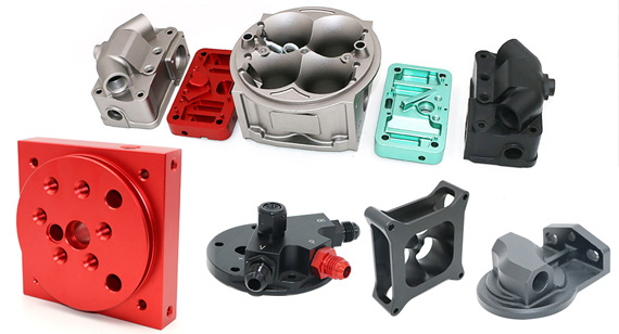
Most CNC parts requiring pressure testing are CNC machined castings. For these components—such as hydraulic manifolds, cylinders & pistons, servo valve bodies, aircraft fuel pump components, and ultra-high vacuum (UHV) chambers—the testing primarily focuses on verifying airtightness, detecting micro-cracks, or conducting high-pressure static and dynamic pressure tests.
SITUATION 2: FOR CNC MACHINED PRECISION PARTS
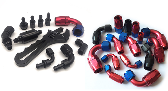
On the other hand, there is a distinct category of precision components that must be manufactured entirely via CNC machining from solid stock. These include flanges & high-pressure fittings, valve cores & seats, rocket propulsion fittings, and high-performance liquid chromatography (HPLC) pump heads. For these CNC machined parts, pressure testing is holding objectives: to verify zero-leakage under extreme high pressure, ensure durability under dynamic cyclic pressure environments, and conduct ultra-high-pressure airtightness and destructive burst testing.

Not every CNC precision part or CNC cast part requires pressure testing—adding it unnecessarily only inflates your production budget. However, you should integrate pressure testing into your project roadmap when facing the following critical scenarios:
Before moving into mass production, testing your prototype is vital to validate the internal architecture of a new design. It ensures that wall thicknesses between interlocking fluid channels (such as complex manifolds) are structurally sound and safe from bursting under operational stress.
High-Risk Applications
If your components are destined for high-risk, high-performance environments, pressure testing is non-negotiable. Classic examples include liquid cooling plates for electric vehicles (EVs), medical fluid control valves, aerospace fittings, and high-pressure hydraulic systems where a single leak could cause unpredictable failure.
Before or After Surface Treatment
Timing your test matters financially. Testing before surface treatments like anodizing, plating allows you to catch defective parts early, preventing you from wasting additional machining hours and processing costs on a scrap component. Conversely, testing after treatment verifies that the coating process hasn't compromised critical thread tolerances or altered the precision of sealing surfaces.
To understand pressure testing comprehensively and clearly, you can separate it into two dimensions: the objective of the test (what you are testing for) and the method used (how you execute it).
Leak vs. Proof vs. Burst Testing—What You Are Testing For
These three ones entirely depend on your purposes, and here' s a clear table to show:
| Test Type | Pressure Range |
Primary Objective |
Non-Destructive? |
| Leak Testing |
Standard working pressure | Verifies airtightness and fluid-tightness; hunts for microscopic paths where gas or liquid might escape. | Yes |
| Proof Testing |
1.5x to 2x working pressure | Validates structural integrity; ensures the component can handle sudden pressure spikes without permanent deformation. | Yes |
| Burst Testing |
Critical failure threshold (Maximum pressure) | Destructive testing; pushes the part until it physically ruptures to verify safety margins during the prototyping phase. | No (Sample testing only) |
Pneumatic Leak Methods—How You Execute It
When your project specifies pneumatic leak testing (using compressed air or nitrogen), the method chosen directly impacts your cost, speed, and accuracy. Here are the three industry-standard methods you can choose:
Air Under Water (Bubble Testing)
This is the most straightforward visual method. The machined part is pressurized with air and submerged in a water tank. It is highly cost-effective and perfect for a quick, baseline screening to catch large, obvious leak paths by watching for escaping bubbles.

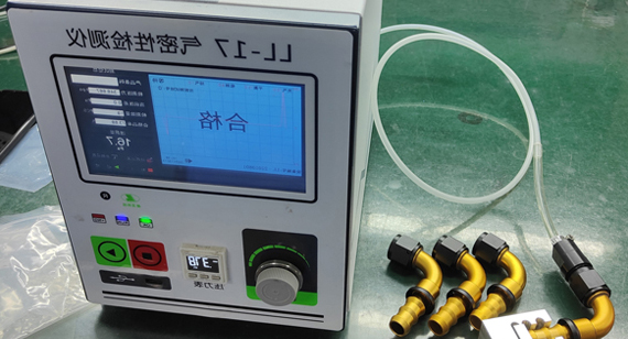
Air Decay (Pressure Decay Testing)
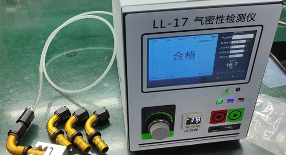
For high-precision components, manual bubble-watching isn't enough. In an air decay test, charge the part with air, seal the supply valve, and monitor the internal pressure over a fixed dwell time using digital transducers. This provides a highly accurate, quantitative analysis capable of detecting invisible micro-leaks (10-5mbar·L/s).
Mass Flow Testing
Instead of measuring a drop in pressure, mass flow testing measures the actual volume of air required to keep the part at a constant, stable pressure. If you need high-volume precision procurement orders to be tested, you can consult suppliers for this method—which is exceptionally fast and highly repeatable.
To ensure the highest accuracy and protect your parts, keep these five top tips in mind:
Tip 1: Demand Zero-Damage Fixturing (Protect Sealing Surfaces)
High-pressure testing requires firm clamping to prevent parts from launching under pressure, but traditional steel clamps can damage precision surfaces. Always insist on custom soft jaws or polyurethane-lined fixtures. These materials securely hold the component under pressure without leaving clamp marks or damaging critical sealing faces and O-ring grooves.
Tip 2: Implement Dual-Stage Air Filtration (Keep the Medium Bone-Dry)
If you are performing high-sensitivity Air Decay or Mass Flow testing, standard factory compressed air will skew your data. Moisture and vaporized oil droplets in the air line interfere with precision digital sensors. Ensure the testing setup utilizes a dual-stage, 0.01-micron coalescing filter to guarantee the test medium is completely dry, preventing false passes or sensor contamination.
Tip 3: Swap Mechanical Gauges for Digital Pressure Transducers
Do not rely on old-school dial gauges for precision validation; they lack the resolution to catch micro-leaks. Move to digital pressure transducers with a resolution down to 1 Pa. This high-level sensitivity allows you to track and log the exact pressure drop curve during the critical dwell time, giving you automated, unalterable data for quality assurance.
Tip 4: Use Gradual, Multi-Stage Pressurization
Never spike the testing pressure instantly. Rapid pressurization creates a massive fluid shockwave that can cause internal channels to flex or experience transient elastic deformation, leading to false leakage readings. Instead, design a gradual, stepped pressure profile (e.g., holding at 30% and 70% before hitting 100%) to let the material stabilize.
Tip 5: Mandate Post-Test Rinse, Bake, and Rust Prevention
If you choose hydrostatic (water) testing, the work does not end when the pressure drops. Leftover tap water causes immediate oxidation inside precision internal threads. Always follow a strict post-test routine: rinse the parts with de-ionized (DI) water to remove mineral deposits, run them through a baking oven for complete moisture extraction, and immediately apply rust-preventative packaging.
Completing the Machining and Pressure Testing of 0.005mm Tolerance for High-Pressure Valve Cores
The clients approached us with their high-pressure fluid parts issues. Their previous supplier failed to meet field reliability standards for custom valve cores. The component required an ultra-tight dimensional and tolerance of ±0.005mm to ensure a flawless seal with the valve seat under 35 MPa working pressure. While these parts passed basic dimensional sampling under traditional calipers, they exhibited fluid bypass and internal leakage during final assembly pressure tests, resulting in expensive system scrap rates and disrupted project timelines for the procurement team.
We utilized premium 440C stainless steel billets (must pass Mill Test Certificate, MTC) and then deployed multi-axis high-precision CNC turning centers coupled with a specialized cylindrical grinding process in a temperature-controlled workshop. This strict thermal control stabilized the metal's micro-expansion, successfully achieving the critical ±0.005mm tolerance while refining the sealing lands' surface finish to an exquisite Ra 0.2 μm. Furthermore, we eliminated microscopic burrs at the intersecting oil ports via automated micro-deburring, removing any sharp edge that could scratch the mating seals during high-pressure cycles.
To protect the finished 0.005mm surfaces from any physical marring, we engineered custom synthetic Delrin fixtures that sealed the valve cores safely without steel-to-steel contact. Every single component underwent a 100% automated, multi-stage hydrostatic test, ramping up gradually to a 1.5x proof pressure of 52.5 MPa with a digital dwell time monitored by 1 Pa resolution pressure transducers. The digital logs yielded a 100% pass rate with zero pressure decay. By partnering with VMT, the client achieved a zero-defect field installation rate, saving over $45,000 in monthly rework costs.

By understanding the nuances of pressure testing, you can confidently protect your design, budget, and trust from customers. This comes down to navigate the complexities of pressure testing: You do not want to risk failures by skipping it, but you also shouldn't inflate your production budget with unnecessary testing when it isn’t required. Striking the right balance keeps your project lean and your timelines on track. For the other aspect, you should ensure that the types and levels of testing that implement are truly robust. Relying on a superficial factory test can create a false sense of security, only for the component to fail later in the field. I believe you surely don't want that kind of situation to happen, leading to expensive product recalls and many claims.
If you want to eliminate these risks and ensure your next project achieves zero-leak precision, partner with VMT CNC Machining Factory to manufacture, test, and validate your critical components with absolute confidence.

What is the difference between air decay and mass flow leak testing for CNC parts?
Air decay measures the drop in pressure inside a sealed part over time, which is highly cost-effective and precise for small volumes. Mass flow testing, on the other hand, measures the continuous rate of air entering the part to maintain constant pressure. Mass flow is faster and ideal for high-volume production runs of complex CNC manifolds.
Why should I choose a solid billet over a casting if my part requires high-pressure proof testing(CNC castings vs CNC precision parts)?
Cast parts inherently suffer from internal porosity (microscopic air pockets), which can rupture or leak under high pressure. CNC machining from solid extruded or forged billets eliminates porosity entirely, ensuring consistent material density and superior performance during 1.5x working pressure proof testing.
Do you perform proof testing or burst testing on custom parts?
For production orders, we perform 100% non-destructive proof testing (usually at 1.5x the rated working pressure) to ensure safety and structural integrity. Burst testing is a destructive method only performed upon customer request during the prototyping phase to verify design safety margins.
Can a part pass an air under water test but fail an air decay test?
Yes. Air under water tests rely on spotting bubbles and are generally effective only for leaks larger than 10-3mbar·L/s. An air decay test is automated and digitally controlled, capable of detecting microscopic leaks down to 10-5mbar·L/s, making it much more reliable for critical fluid systems.
What does "certified pressure testing for CNC parts" mean, and why is it important?
Certified pressure testing means the testing is executed under strict quality standards (such as ISO 9001:2015 or IATF 16949:2016) using calibrated digital equipment. It provides formal, traceable documentation—such as a leak test certificate—proving your component passed precise pressure limits.
Why is "CNC manifold pressure testing" uniquely critical compared to other machined components?
Hydraulic and fluid manifolds feature complex networks of deep, intersecting internal channels. These cross-sections are highly prone to hidden defects like microscopic machining burrs, tool marks in O-ring grooves, or material porosity if machined from castings. Specialized manifold pressure testing—such as air decay or hydrostatic testing—is the must way to catch these internal flaws and guarantee zero-leak performance before the block is fully assembled into a high-pressure system.

 +86 15099911516


 Read more