16 years one-stop China custom CNC machining parts factory

Hey there I’m VMT Sam!
With 25 years of CNC machining experience we are committed to helping clients overcome 10000 complex part-processing challenges all to contribute to a better life through intelligent manufacturing. Contact us now
 46 |
Published by VMT at Nov 17 2026 | Reading Time:About 6 minutes


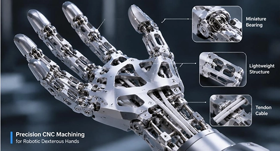
Different robotic hand grasping modes require different mechanical and manufacturing priorities. Pinch grasp depends more heavily on fingertip positioning, miniature joint fits, and backlash control; power grasp requires greater phalanx rigidity and stable thin-wall structures; and adaptive grasp relies on controlled linkage clearances and low-friction tendon routing. For CNC-machined dexterous hand components, these kinematic requirements should be translated into material, tolerance, surface-finish, and machining decisions during the DFM stage to reduce joint binding, tendon wear, structural deformation, and prototype rework.
The grasping performance of custom CNC machined robotic dexterous hands and fingers depends on both kinematic design and precision manufacturing. Pinch Grasp places greater emphasis on fingertip positioning accuracy, miniature pin-hole fits, and joint clearance. Power Grasp relies more heavily on phalanx rigidity, thin-wall machining stability, and load transfer capability. Adaptive Grasp requires controlled linkage clearances, along with appropriate surface quality and transition geometry in tendon routing channels. Considering these machining, tolerance, and surface-finish requirements early in the design process helps reduce prototype assembly issues, shorten development cycles, and improve the operational stability of robotic end effectors.
The case study at the end of this article explains how our manufacturing team recommended switching the proximal and intermediate phalanges to 7075-T651, redesigning the wall thickness, and applying 5-axis micromachining to address tendon wear caused by tool marks and internal drive motor binding resulting from a 0.5 mm shift in the intermediate finger joint pivot position.
CNC machined robotic hands & fingers generally use three foundational grasping modes: Pinch Grasp, Power Grasp, and Adaptive Grasp. Each grasping mode places different mechanical loads on the finger phalanges, joint connections, and transmission systems, resulting in different structural design and manufacturing priorities.
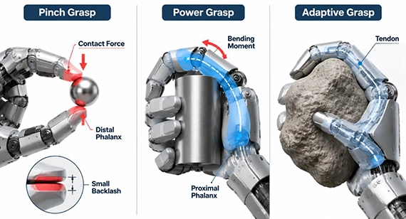
| Grasping Mode | Primary Mechanical Objective | Critical Phalanx Region | Key CNC Machining Priority |
| Pinch Grasp | Precise fingertip contact and controlled joint backlash | Distal phalanx (fingertip) | Tight hinge pin tolerances and flat sensor mounting surfaces |
| Power Grasp | Larger contact area and higher load capacity | Proximal phalanx | Thin-wall pocketing, rib rigidity, and vibration control |
| Adaptive Grasp | Passive compliance around irregular objects with reduced transmission resistance | Intermediate linkages and tendon routing | Burr-free micro channels and consistent linkage pin-hole positions |
1. Pinch Grasp: Fingertip Structures and Miniature Joint Requirements
A pinch grasp uses the distal phalanges to hold small or delicate objects through fingertip contact. Because the contact area is relatively small, clearance and backlash within the kinematic chain can directly affect fingertip positioning accuracy and contact force control.
Distal Phalanx Design and Sensor Housings
The distal phalanx typically accommodates tactile arrays, force sensors, or high-friction gripping pads.
Miniature Pivot Joint Tolerances
Fingertip joints commonly use miniature stainless steel dowel pins or miniature ball bearings to establish rotational connections. Robotic finger joint geometry tolerances should account for bore dimensions, positional relationships, and mating clearances.
2. Power Grasp: Structural Rigidity and Thin-Wall Pocketing
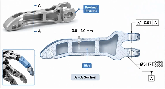
Power grasping wraps the proximal and intermediate phalanges around an object to increase contact area and improve load-bearing capability. Compared with precision pinch movements, this grasping mode places greater demands on overall finger rigidity, bending resistance, and joint load transmission.
Load Transfer and Bending Moment Control
The proximal phalanx typically experiences significant cantilever bending moments under higher gripping loads. Excessive deformation during operation can lead to several problems:
Therefore, robotic finger design should consider not only static strength but also deformation under operating loads and its influence on internal joint alignment.
Thin-Wall Pocketing and Weight Reduction
To reduce the end-effector load and rotational inertia, a weight-reduction pocket design is recommended inside the phalanges while retaining the necessary reinforcing ribs.
3. Adaptive Grasp: Linkage Clearances and Tendon Routing
Adaptive robotic hands use underactuated multi-bar linkages or tendon networks to adjust finger geometry around irregular objects without requiring an individual actuator for every joint. The mechanics of adaptive grasping mechanisms need to balance motion compliance, transmission resistance, and joint clearance.
Multi-Bar Linkage Fits
An underactuated robotic finger relies on passive movement and compliance between linkages. Excessive pin-to-hole clearance can cause finger sagging and reduce motion repeatability. Insufficient clearance can increase rotational resistance and interfere with the finger's return movement.
Internal Tendon Routing Channel Machining
Tendon-driven robotic hands route braided steel wires or ultra-high-molecular-weight polyethylene (UHMWPE, such as Dyneema) cables through internal finger channels.
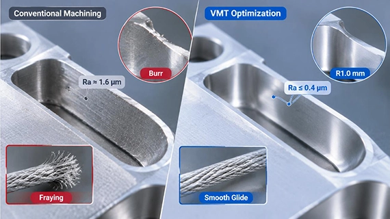
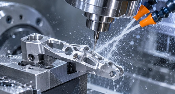
Robotic finger components are generally small, with complex organic contours, internal channels, and mounting interfaces distributed across multiple faces. For parts involving angled bores and complex cavities, conventional 3-axis milling can face limitations in setup efficiency and feature-position control.
Micro-Milling and Miniature Thread Machining
Design for manufacturability (DFM) during the early development of robotic dexterous hands helps reduce repeated design revisions, assembly problems, and unnecessary machining costs. For miniature robotic finger components, material selection, wall thickness, tolerances, and surface treatments should be evaluated together according to their functional requirements. DFM for robotic hand parts should assess not only whether a component can be machined but also whether it can achieve the required assembly accuracy and motion performance.
Common Materials for Custom CNC Machined Robotic Dexterous Hand & Finger Components
Common Practical DFM Practices for Machining Cost Optimization
Precision Machining for a Humanoid Dexterous Hand to Solve Tendon Wear and Internal Drive Motor Binding
A humanoid robotics development company was developing an underactuated five-finger dexterous hand. During functional testing, the 6061 aluminum prototype machined by its previous supplier revealed two major problems:
Because these problems involved internal channel surface quality, thin-wall structural rigidity, and joint alignment accuracy, the customer subsequently approached our engineering team for a reassessment of the material, structure, and machining process to improve the prototype's actual operating performance.
Results
After the improvements, the tendon cable completed 100,000 continuous test cycles without fraying or tension loss. Phalanx deflection was kept below 0.02 mm under maximum gripping loads, while the intermediate joint operated without motor binding. These results restored consistent finger movement and improved grasping repeatability.
In robotic end-effector development, grasping performance depends not only on kinematic design but also on structural rigidity, miniature joint fit accuracy, and the surface quality of internal transmission features. Digital simulations often simplify factors such as rigid-body deformation, joint clearance, and friction in tendon-driven mechanisms. During physical prototype testing, however, issues such as loose fingers, joint binding, structural bending, and reduced effective gripping force can become apparent.
These problems are often related to discrepancies between design requirements and manufacturing results. Achieving flexible and stable grasping requires a balance between kinematic requirements and actual machining capabilities. Converting a CAD design into a reliable physical mechanism requires custom CNC machined robotic dexterous hand and finger components that meet the demands of miniature structures and precision fits.
Are you currently facing manufacturing challenges such as miniature pin-hole and bearing-seat fit deviations, misalignment between dual-clevis hinge bores, thin-wall phalanx deformation, or burrs and surface wear inside tendon routing channels? Contact our engineering team for a free evaluation of dimensional tolerances, fit relationships, material selection, thin-wall structures, and machining feasibility. You can also receive a tailored CNC machining solution, prototype manufacturing support, and an accurate quotation. [We support 2D Drawings (PDF files), 3D Drawings (IGS/STP/STEP files)].
Send your 2D drawings, 3D CAD models, grasping mechanism details, material, joint-fit requirements, hinge and bearing tolerances, tendon-routing features, wall thicknesses, surface finish, prototype quantity and production quantity. VMT will review DFM, 5-axis machining, micromachining feasibility, thin-wall stability, tendon-channel finishing, inspection and quotation requirements.
All information and uploaded files are secure and confidential.
1 Tell us what you need
2 Get solution & quote
3 Approve production
Email: inquiry@vimetal.com.cn
1. What are the main mechanical differences between Pinch Grasp and Power Grasp in robotics?
Pinch grasping uses two or more fingertip contact points to hold an object. It prioritizes fingertip positioning accuracy, contact force control, and minimal joint backlash. Power grasping wraps multiple finger segments around an object to increase contact area, placing greater emphasis on structural rigidity, load transmission, and bending resistance across the phalanges.
2: Should You Choose Titanium or Aluminum for CNC Machined Robotic Hand and Finger Components?
Titanium and aluminum alloys differ in strength-to-weight ratio, thermal conductivity, machinability, and cost. Although both materials are suitable for lightweight design, and aluminum offers advantages in processing, cost, and heat dissipation while titanium offers advantages in strength and corrosion resistance, the appropriate choice ultimately depends on the load requirements, target weight, joint configuration, and manufacturing complexity of each component. For a detailed comparison, see [Titanium vs. Aluminum for Custom CNC Machined Dexterous Robotic Hand & Finger Components].
3: What CNC Machining Processes Are Used to Manufacture Precision Robotic Dexterous Finger Parts?
Manufacturing precision robotic finger parts may involve 5-axis CNC machining, micromachining, thin-wall milling, and precision finishing. The process selection depends on the component geometry, miniature features, tolerance requirements, and internal tendon routing structures. For more details, see [How to Manufacture Precision CNC Parts for Robotic Dexterous Fingers].
4. What CNC machining tolerances are typically required for miniature robotic knuckle pins and bearings?
Miniature pivot bores may use ISO H7 or H6 tolerance grades depending on the required bearing and pin fit. Corresponding pin diameters can be specified using h6 or g6 grades according to bore dimensions, material, and assembly requirements. For dual-clevis hinge designs, bore parallelism can be controlled within 0.01 mm when required by the motion and assembly specifications.
5. What surface finish is recommended for internal tendon channels to reduce friction and wear?
An internal tendon channel surface finish of Ra 0.4 µm or better can be used as a precision finishing target. Rough internal surfaces increase friction and wear as cables move repeatedly under tension. For aluminum components, Type III hardcoat anodizing with PTFE sealing can also be evaluated according to the cable material and actual friction conditions.
6. How should wall thickness be selected for lightweight aluminum robotic finger phalanges?
For structural aluminum alloys such as 6061-T6 and 7075-T6, 0.8–1.0 mm can serve as an initial wall-thickness reference for selected lightweight robotic finger structures. The final dimensions should be validated against phalanx length, loading conditions, rib layout, clamping methods, and machining deformation. Excessively thin walls increase the risk of milling vibration, sidewall deflection, and dimensional variation caused by residual stress release.
The technical information and manufacturing advice shared on the machining-custom.com website are for general guidance only. While we strive for accuracy, machining-custom.com does not guarantee that the processes, tolerances, or material properties mentioned are applicable to every specific project. Any reliance you place on such information is strictly at your own risk. It is the buyer's responsibility to provide definitive engineering specifications for any production orders. Final specifications and service terms shall be subject to the formal contract or quotation confirmed by both parties.


 +86 15099911516




 Read more