Engineering Guide
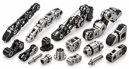
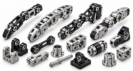
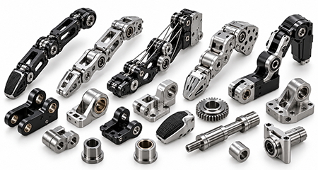
Engineering Guide to Custom CNC Machined Robotic Dexterous Hand & Finger Components
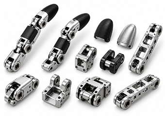
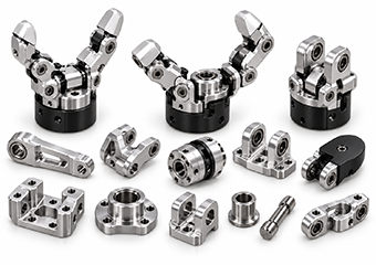
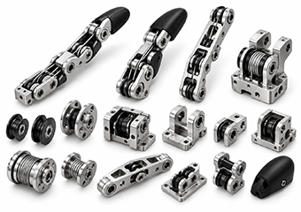
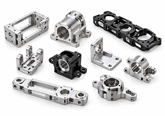
This guide explains how finger geometry, joint datums, transmission design, material, finishing and inspection affect whether a robotic-hand component is merely “within size” or actually ready for assembly and repeat manufacturing.
1. What Should a Robotic Finger Drawing Define First?
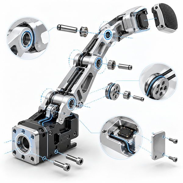
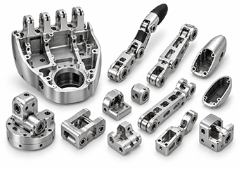
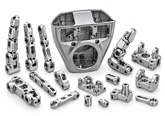
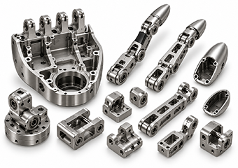
A robotic finger drawing should first separate the features that establish motion and assembly from general geometry. Pivot bores, joint-axis locations, linkage centers, actuator locating features, bearing or bushing fits and pulley interfaces usually have a much stronger effect on the finished mechanism than cosmetic outer profiles.
When every dimension is given the same tight tolerance, the supplier spends machining and inspection time on features that may not improve function. A better RFQ identifies which dimensions locate the finger mechanically, which dimensions only control clearance, and which surfaces are cosmetic. That allows DFM, fixturing and inspection to be organized around the actual motion chain.
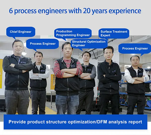
For VMT, this is the starting point for deciding whether a feature should be completed in the same setup, whether CMM verification is needed and whether a finish-sensitive dimension must be evaluated after anodizing or coating.
View Full Robotic Dexterous Hand Engineering Guide
2. Which Datums and GD&T Matter Most?
The most useful datum structure is the one that reflects how the part is located inside the hand. For a joint component, that may be a mounting face plus a pivot axis; for an actuator mount, it may be the motor pilot, locating face and downstream linkage relationship. GD&T should describe these relationships clearly enough that machining and inspection can use the same reference system.
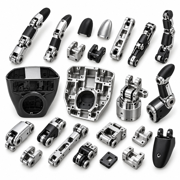
Size tolerance alone cannot describe every functional risk. Position, perpendicularity, parallelism, coaxiality or profile may matter more when several features must align to a common motion axis. Suitable critical dimensions can be controlled to ±0.005 mm after VMT engineering review, but no single tolerance value should be applied to every robotic-hand feature.
3. How Should Lightweight Phalanges Be Machined Without Losing Stability?
Weight reduction is valuable because every gram in a moving finger contributes to inertia, but aggressive pockets and thin walls also reduce machining stiffness. Heavy stock removal can release residual stress; excessive clamp force can temporarily pull the part into tolerance; and deep pockets can increase tool deflection.
A stable route normally separates roughing from final critical-feature machining. Stronger datum areas are preserved long enough to support the part, clamp pressure is controlled, and critical joint geometry is finished after the main stock-removal stage. Where the geometry is sensitive, free-state verification after release provides more useful information than checking only while the part remains clamped.
4. How Do Tendon-Driven and Linkage-Driven Designs Change the Machining Plan?
Tendon-driven designs shift attention toward pulley concentricity, groove geometry, cable clearance and burr control. A cable can be damaged by a small edge defect that would be irrelevant on a non-contact cosmetic surface. Turning or mill-turn is often a logical route for pulleys because the bore and groove can remain related through the rotational setup.
Linkage-driven designs place more emphasis on pivot-center relationships. Correct hole diameter does not guarantee the intended motion if the hole centers drift. Related pivot features therefore benefit from a common datum strategy and positional inspection. The manufacturing plan should follow the transmission architecture instead of treating every component as an isolated CNC part.
5. How Should Material Be Selected for Robotic Dexterous Hand Components?
There is no single “best” robotic-hand material. 6061-T6 is useful for economical lightweight structures and mounts; 7075-T6 increases strength while retaining aluminum's mass advantage; titanium Grade 5 can be reserved for high-load lightweight parts where its higher cost is justified; and stainless or alloy steel can be concentrated in smaller pins, shafts and wear interfaces.
The practical goal is mixed-material optimization: keep moving structures light, place stronger or more wear-resistant material where the load actually demands it, and consider the downstream surface treatment before the final grade is frozen.
6. How Do You Protect Critical Fits During Anodizing, Plating or Coating?
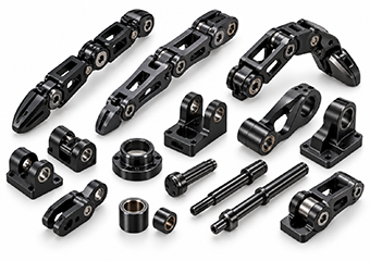
Surface finishing changes the final component condition. Anodizing can reduce the effective diameter of an internal bore, plating adds material to mating interfaces, and hard coatings can change a sliding or press fit even when the machined part was correct before finishing.
The drawing should therefore distinguish cosmetic surfaces from functional interfaces. Depending on the process, VMT can coordinate allowance, masking, plugging and post-finish inspection. For joint bores, actuator pilots, threaded areas and pulley interfaces, the meaningful acceptance condition is the finished part that will actually be assembled.
7. How Should Robotic Finger Parts Be Inspected?
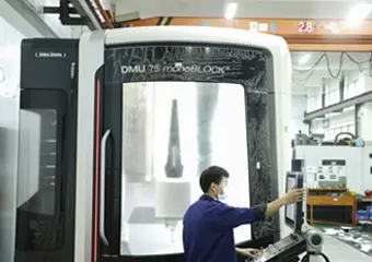
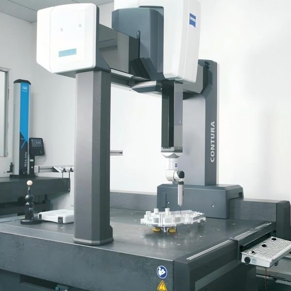
Inspection should follow functional risk. A caliper can confirm an outside dimension, but it cannot fully verify the relationship between several pivot axes, linkage centers and actuator datums. VMT therefore combines conventional gauges, optical measurement and CMM according to the geometry.
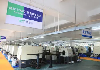
The broader quality system uses 12 control steps across incoming material, first article, in-process and final inspection. Agreed critical features can receive 100% checking. For repeat production, the approved datum structure and inspection points should remain tied to the same drawing revision so the process does not drift between batches.
8. What Affects Cost and What Should Be Frozen Before Repeat Production?
Robotic-hand machining cost is driven less by physical size than by process complexity: number of setups, 5-axis access, small cutters, thin walls, hard materials, tight geometric relationships, CMM time, surface treatment and quantity. One of the most effective ways to reduce cost is to reserve the tightest tolerances for features that actually control motion and assembly.
Before repeat production, freeze the approved CAD/drawing revision, material, surface finish, critical GD&T, masking requirements, inspection method and left/right identification. Once these items are stable, fixture strategy, tooling, machining sequence and inspection checkpoints can be retained instead of being rediscovered on every order.
 +86 15099911516
 inquiry@vimetal.com.cn



 Up to ±0.005 mm for Suitable Critical Joint Features