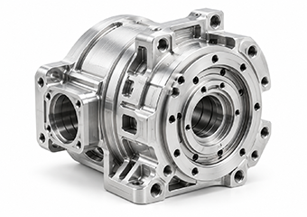
Integrated Rotary Actuator Main Housings
Main bodies combine motor, reducer, bearing and output interfaces; VMT controls the functional axis, thin-wall stability and related datums before final verification.

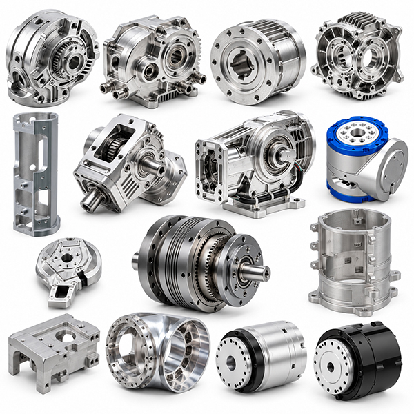
VMT custom CNC machines robotic actuator housings and components with ±0.005 mm precision capability coaxial fit control thin-wall machining CMM inspection and prototype-to-production support.
 0.008–0.01 mm Concentricity Control for Critical Actuator Interfaces
1 mm Thin-Wall Machining with Deformation Control
Single-Setup 5-Axis Machining to Reduce Datum Transfer & Assembly Misalignment
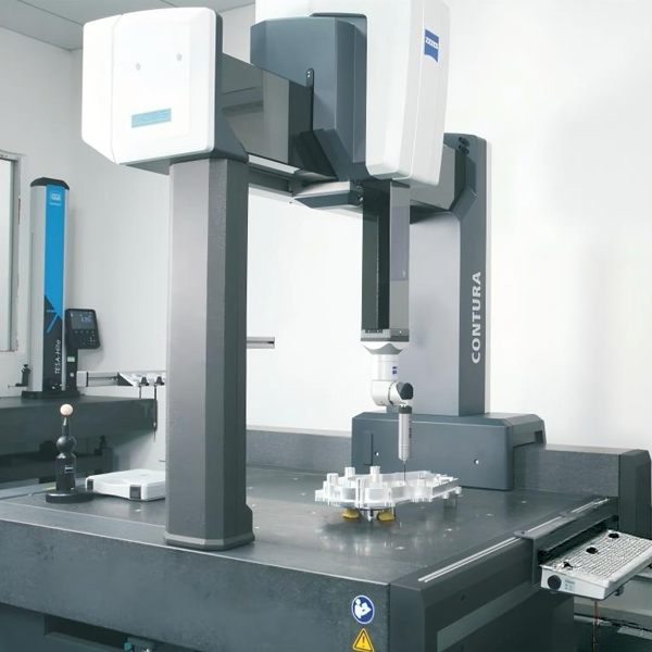
100% Critical Dimension Inspection with CMM Support
Finish-Aware Machining with Masking, Allowance & Post-Coating Fit Verification
1 DayPrototyping Machining
2 HoursQuick Quote
0 PcsMinimum Order Qualities
98%Yield


VMT manufactures drawing-defined robotic actuator housings and mechanical components around the interfaces that determine assembly: motor location, reducer alignment, bearing fits, encoder positioning, output geometry and cable routing. DFM review, multi-axis machining, in-process control, CMM inspection and finish-aware verification support your project from prototype validation to repeat production.
Different actuator components locate different elements in the drive stack. VMT plans machining around each part’s actual assembly role instead of treating every housing as the same type of CNC enclosure.
Main bodies combine motor, reducer, bearing and output interfaces; VMT controls the functional axis, thin-wall stability and related datums before final verification.
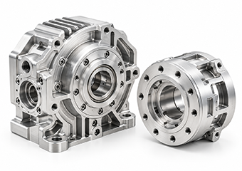
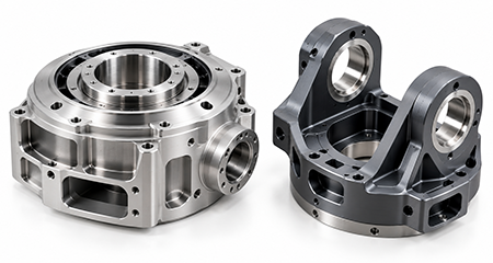
Motor housings locate stator, bearings and mounting interfaces; turning and milling establish circular registers, faces and bolt patterns for repeatable actuator alignment.
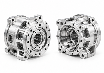
Reducer housings require controlled bores, shoulders, faces and bolt patterns, with the machining route built around one functional datum structure.
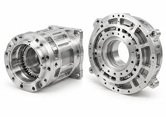
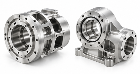
Gear reducer cases support multiple bearing and gear locations; turning, mill-turn or multi-axis machining is selected according to geometry and axis relationships.
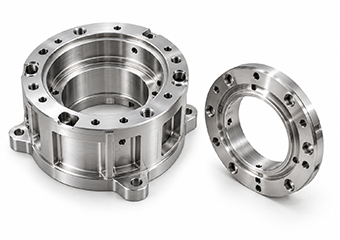
Bearing carriers control seat diameter, shoulders and axial location; VMT treats these features as one functional fit rather than unrelated dimensions.
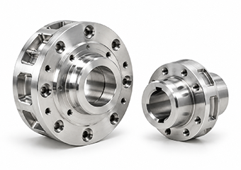
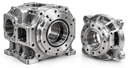
Output interfaces transfer torque into the robot structure; concentric pilots and faces are established before hole patterns, flats and secondary features are added.
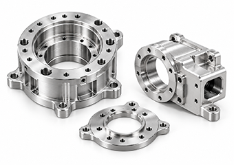
Feedback-side components require stable positioning relative to the rotational axis, including locating features, protective covers and burr-controlled cable openings.
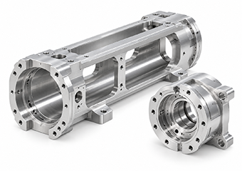
Linear actuator structures may combine screw, guide, motor and mounting interfaces, making bore alignment, end faces, threads and straightness relationships important.
The risk is rarely one isolated tolerance. Actuator performance depends on several bores, shoulders, mating faces and finish-sensitive interfaces staying related after roughing, re-clamping and surface treatment.
A bore can pass diameter inspection while its axis still disagrees with the reducer or bearing centerline, creating runout, difficult assembly or uneven load distribution.
Clamping pressure, cutting heat, residual stress and unbalanced stock removal can move precision interfaces after the housing is released from the fixture.
Bearing fit depends on bore size, roundness, shoulder position and the related face—not diameter alone—so inspection must reflect how the bearing actually seats.
Reducer and output interfaces need accurate locating faces and bolt patterns; repeated datum transfer can create errors that only become obvious during final actuator assembly.
Anodizing and plating can change bearing seats, pilots, threads and contact faces. A good raw-machined part can become too tight or misaligned after coating.
Internal passages and cross-holes can become inaccessible after later operations, and burrs can damage cable insulation or interfere with routing inside compact actuators.
VMT first identifies which bores, pilots, faces and shoulders actually locate the motor, reducer, bearings and output side, then uses those functional relationships to decide the datum strategy, setup sequence, distortion control and finishing plan.
We align the motor register, reducer seat, bearing bores and output pilot to one functional datum; VMT robot-joint machining has controlled concentricity to 0.008–0.01 mm.
This keeps the machining and CMM plan on the same reference structure used by the actuator assembly, reducing the risk that individually acceptable features disagree on the final centerline.
Where geometry allows, related bores, pilots and faces stay in one 5-axis or mill-turn setup; one VMT robot-joint route reduced fixture cost by about 40%.
Fewer re-clamping steps reduce datum-transfer error between motor, reducer, bearing and output interfaces while also simplifying fixture validation.
For thin or heavily pocketed housings, VMT can separate roughing, stabilization and final machining; motor-housing work has combined 1 mm walls, many dimensions within 8 μm and 0.01 mm concentricity.
Critical bores and faces are finished after the structure has released most machining stress, reducing the chance that the housing moves after unclamping.
Bearing seats, pilots, threads and mating faces are protected, compensated or rechecked after coating, with 100% critical inspection available for specified finished fits.
This prevents a housing from passing raw-machined inspection but failing final assembly after anodizing or plating changes the effective fit.
The motor, reducer, bearings, encoder and output interface create one tolerance chain, so DFM and inspection must protect their relationship instead of checking each feature in isolation.
Material selection affects moving mass, stiffness, corrosion resistance, bearing support, finishing and cost. These cards connect each common material to the actuator function it is most likely to support.
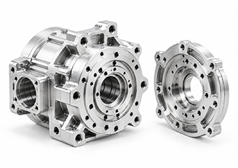
6061-T6 suits actuator housings and covers, combining low weight and machinability with anodizing compatibility to deliver cost-effective, repeatable prototype-to-production assembly.
Get a Quote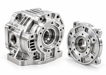
7075-T6 suits high-load compact housings and output interfaces, combining high strength and stiffness with hard anodizing to reduce moving mass while protecting durability.
Get a Quote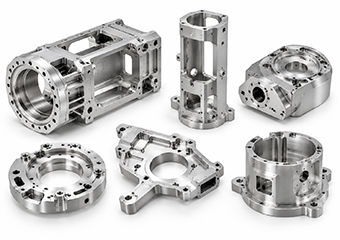
6082-T6 suits structural housings and mounting adapters, balancing strength, corrosion resistance and machinability with anodizing to provide durable, cost-efficient robotic actuator structures.
Get a Quote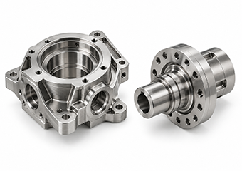
17-4PH suits bearing carriers, shafts and high-load interfaces, combining high strength and corrosion resistance with passivation to support durable, dimensionally stable actuator assemblies.
Get a Quote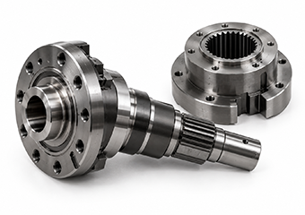
4140 / 42CrMo suits shafts, hubs and high-load drive interfaces, offering strength and wear resistance with grinding or protective finishing for reliable torque transmission.
Get a Quote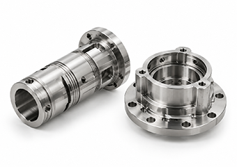
304 / 316 stainless steel suits sleeves, spacers and corrosion-sensitive hardware, combining corrosion resistance and toughness with passivation to deliver reliable service in demanding environments.
Get a Quote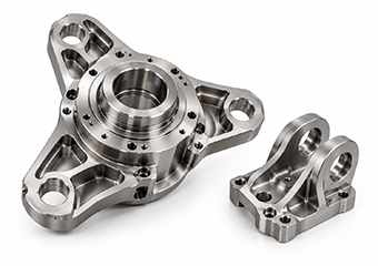
Titanium Grade 5 suits lightweight, high-load flanges and connectors, combining high specific strength and corrosion resistance with suitable finishing to reduce actuator mass without sacrificing strength.
Get a Quote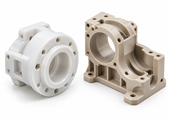
POM / PEEK suits spacers, cable guides and insulating supports, combining low friction or temperature resistance with clean machining to improve isolation, routing and assembly reliability.
Get a QuoteThe finish is part of the dimensional plan, not a cosmetic step added at the end. Bearing seats, pilots, threads, mating faces and grounding areas are reviewed before finishing so the accepted part matches the condition used in assembly.
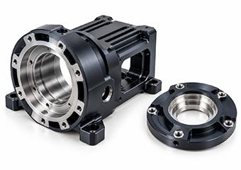
Improves corrosion resistance and color on aluminum housings; critical bores, pilots and contact faces are reviewed for masking or finished-size allowance.
Get a Quote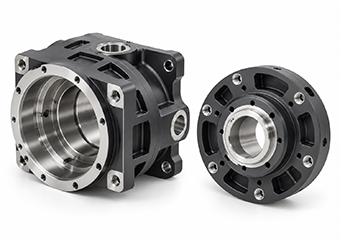
Adds wear-resistant oxide on functional aluminum components, but coating buildup must be planned around bearing seats, threads and high-precision mating interfaces.
Get a Quote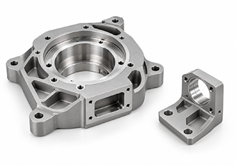
Creates a uniform matte aluminum appearance while machining marks, visible surfaces, masked fits and post-finish dimensional checks are coordinated before release.
Get a Quote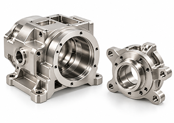
Provides corrosion and wear protection on suitable complex metal geometry, with coating thickness reviewed where bearing fits, bores or threaded features remain functional.
Get a Quote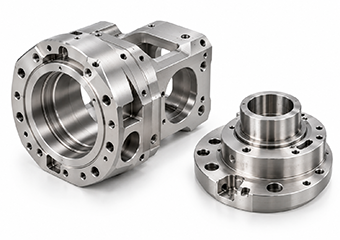
Improves stainless-steel corrosion resistance without adding a thick dimensional coating, making it useful around precision interfaces where fit change should be minimized.
Get a Quote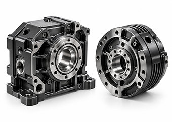
Supports selected wear or friction-sensitive interfaces when substrate compatibility, coating thickness and final fit are reviewed before machining and coating release.
Get a Quote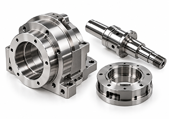
Supports drawing-defined seats, shafts and contact surfaces that need additional surface condition or final dimensional control beyond primary milling or turning.
Get a Quote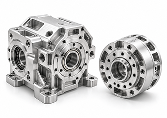
Adds part numbers, revision marks, orientation marks or branding after machining and finishing without intentionally changing critical actuator mating geometry.
Get a QuoteEven when individual dimensions are within tolerance, actuator components can still fail assembly if bearing bores, reducer seats, mounting faces and output pilots do not locate correctly to each other. VMT builds the inspection plan around these functional relationships, with suitable critical dimensions controllable to ±0.005 mm and 100% inspection available when required.
Bearing fit depends on bore size, roundness and shoulder position. VMT checks size with bore gauges or micrometers and uses CMM when the bore and shoulder are controlled from a common datum.
Separate diameters can all pass inspection and still disagree on the rotational axis. VMT verifies coaxial and positional relationships from the drawing datum system with CMM and reduces unnecessary re-clamping.
Reducer and output faces must seat squarely and the bolt pattern must locate from the intended datum. VMT checks these GD&T relationships by CMM or suitable height/position measurement during first article and IPQC.
Anodizing or plating can change bearing seats, pilots and threads after raw machining. VMT plans masking or pre-finish allowance, then rechecks critical bores and uses thread gauges where applicable.
Validate envelope, internal clearance, bearing fit, motor/reducer interfaces, cable routing and assembly access before freezing the design.
Use production-intent material and finishing where needed to verify finished fits and the complete mechanical interface stack.
Stabilize workholding, machining sequence, inspection points, finishing requirements and drawing revision control before volume increases.
Carry the approved program, fixture references, inspection requirements and finishing instructions into later orders to reduce process drift.
VMT supports customers in 62+ countries across robotics, industrial automation, automotive, electronics and medical manufacturing. For robotic actuator projects, we turn drawing-defined concepts into machined housings and components from prototype validation through repeat production, helping control moving mass, bearing and reducer alignment, finished fits and repeatable assembly.
Shoulder, elbow, hip, knee and ankle actuators combine compact housings with dense bearing, reducer and cable-routing interfaces where moving mass matters.
Cobot drive modules need compact mechanical interfaces, controlled fits and repeatable finished geometry to support smooth assembly and repeated motion.
Industrial actuators use durable reducer, bearing and output interfaces designed for repeated motion, production uptime and service-oriented assembly.
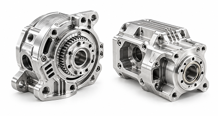
Legged robots use compact rotary actuators that balance weight, impact loading, stiffness, cable routing and high-density mechanical packaging.
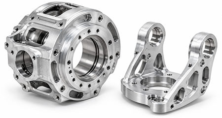
Wearable robotic systems benefit from low-mass actuator housings with reliable motor, reduction, bearing and joint-interface alignment.
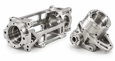
Development platforms frequently change geometry between revisions, making flexible prototype quantities and early DFM review valuable during concept validation.
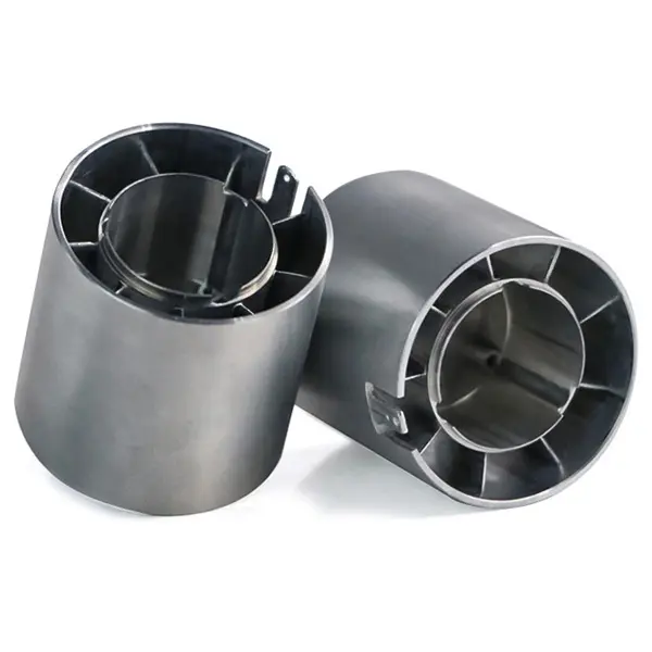
VMT manufactured a 6061 aluminum high-speed micro motor housing requiring extremely tight dimensional control, 0.01 mm concentricity and a 1 mm thin-wall structure. The process had to control deformation, concentric rotating features and production stability while using die casting plus CNC machining to balance precision and cost.
At VMT, the job is not finished when machining stops. We focus on delivering parts that pass your inspection, assemble correctly and give you confidence to move from sample approval into repeat production. The feedback below shows how customers describe the quality, service and results after receiving their custom parts.
“Your parts were perfect, thank-you. I want to order a production quantity soon.”
“We have now tested the samples and found out that their quality was very good. So, we would like to order a batch of 1000 pcs of each type for our production.”
“I am happy with the quality of the product. Thank everyone for an excellent job.”
“Yes! All is good. Thanks for doing a great job!”

Customer feedback screenshots with personal contact information obscured.
This guide is written for engineers and buyers preparing actuator housings for quotation, prototype validation or production transfer. It focuses on the decisions that change machinability, assembly risk, inspection cost and repeatability.
A robotic actuator housing is not simply a protective enclosure. In a compact rotary actuator, the housing may locate the motor, reducer, one or more bearings, encoder or feedback components, output flange and cable path at the same time. This means the functional risk comes from the relationship between these features. A bearing bore can be perfectly within size tolerance but still fail if its axis is offset from the reducer seat; a flange can be flat but still create assembly error if it is not perpendicular to the actuator centerline.
Before machining, define which features establish the actuator’s centerline and axial stack. Mark the motor register, reducer locating diameter, bearing seats, output pilot and any encoder datum as functional interfaces on the 2D drawing. Where these relationships control performance, use appropriate GD&T rather than relying only on ± size tolerances. This gives the machining supplier a clear basis for fixture design, setup reduction and CMM programming.
For VMT, the practical objective is to connect DFM, machining and inspection around the same functional axis. That reduces the risk of the familiar failure mode where every individual size passes but the motor, reducer or bearing stack still does not assemble correctly.
Datum selection should reflect how the actuator is assembled and loaded. A practical approach is to establish a primary rotational datum from a critical bore or pilot, a secondary axial datum from a functional mating face, and a tertiary orientation datum from a bolt pattern, key feature or locating face. The exact scheme depends on the architecture, but machining and inspection should reference the same relationships used by the motor, reducer and output components during assembly.
Position, perpendicularity, flatness, profile and runout are often more useful than simply tightening every diameter. VMT reviews which relationships require CMM verification and which dimensions can be controlled economically with gauges, micrometers, height gauges or in-process probing. Suitable critical dimensions can be controlled to ±0.005 mm after engineering review.
Robotics teams often remove material aggressively to reduce moving mass, but every pocket also reduces stiffness during machining. The most sensitive areas are usually around bearing seats, reducer faces, output pilots and narrow ribs connecting functional interfaces. Thin walls can deflect under fixture pressure, move as residual stress is released, or spring after the part is unclamped.
When distortion risk is high, VMT can separate heavy roughing from later finishing, leave stock on critical interfaces, stabilize the part, then complete semi-finishing and final machining after the structure has settled. VMT motor-housing machining experience includes 1 mm thin-wall sections, many dimensions within 8 μm and 0.01 mm concentricity after process validation.
5-axis machining is valuable when several precision interfaces lie on different faces or angles and reducing re-clamping protects their datum relationships. Cylindrical main bodies, output hubs and bearing carriers often benefit from CNC turning or mill-turn because concentric IDs, ODs and shoulders can be established from one rotational setup before secondary holes and flats are added.
3/4-axis milling remains appropriate for many motor mounts, adapter plates, covers and accessible housings. The best process is the one that achieves the required relationship with the fewest unnecessary setups and the lowest controllable cost.
6061-T6 is often a practical starting point for housings because it combines low density, machinability, corrosion resistance and anodizing compatibility. 7075-T6 becomes attractive when higher strength and stiffness are needed without adding moving mass. 6082-T6 can suit structural mounts and housings, while 17-4PH, 4140/42CrMo and titanium are more relevant to high-load hubs, carriers, shafts and interfaces where strength, wear or corrosion performance justifies the additional cost.
Material should be selected from the actuator’s load path, operating environment, surface finish, target weight and production quantity—not from a generic stronger-is-better rule.
Anodizing, hard anodizing, nickel plating, PVD and other finishes change the final surface condition. On actuator components, that matters most at bearing seats, reducer pilots, motor registers, threads, grounding surfaces and tightly fitted mating diameters. The drawing should clearly state whether the dimension applies before or after finishing and which areas must remain uncoated.
VMT connects machining allowance, masking instructions and post-finish inspection during DFM so finishing does not turn a good raw-machined component into an assembly reject.
Inspection should prove the functions that matter rather than create a long list of unrelated measurements. Typical checks include bearing bore size and roundness, shoulder and face position, reducer locating diameter, bolt-pattern position, perpendicularity between the rotational axis and mating faces, output-pilot relationship, threads, cable-path burrs and post-finish fit.
VMT uses first-article, in-process and final checks, with CMM for drawing-controlled positional relationships and 100% critical-feature inspection available when the project requires it.
The largest cost drivers are usually material removal, number of setups, deep or inaccessible features, extremely tight tolerances, thin-wall stabilization, special tools, CMM time, surface-finishing masking, post-finish inspection and order quantity. Applying tight tolerances only to the features that control the actuator stack can reduce machining and inspection cost without weakening function.
For quotation, provide 3D CAD, a controlled 2D drawing, material, prototype and production quantities, surface finish, critical GD&T, roughness, inspection requirements and any mating-part information that explains the functional interfaces.
Send your 2D drawing or 3D model with material, quantity, surface finish and critical interface requirements. VMT can review machining access, datum relationships, thin-wall risk, bearing and reducer fits, inspection requirements and the prototype-to-production route before quotation.

 2024-08-02
The manufacturer is strongly recommended. In the past few years of cooperation we have ordered several machined products from aluminum and stainless steel. These products are manufactured in compliance with tolerance requirements and require product finish. Now I have ordered another one. The service is excellent and any questions can be answered and resolved in time.
 2021-05-13
The dimensions are all customized according to my drawings no tolerance issues and the parts are delivered on time. I am very satisfied with it.
 2021-04-06
I pay much attention to the surface treatment aspect of this product. I was a little worried about the cooperation at the beginning. I am very satisfied with the product now and hope to cooperate for a long time.
 2022-09-22
AN8 Straight PTFE Hose End Fitting for PTFE Fuel Line Fitting Adapter Black Blue Red


 +86 15099911516