Free cookie consent management tool by TermsFeed Cookies

Home / Product / Aluminum Parts /

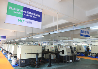
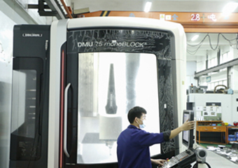
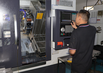
As your aluminum CNC machining manufacturer, we have 40+ aluminum alloy materials, 100 CNC machining equipment, and 12 quality inspection processes. can provide you with a solution tailored to your specific needs.


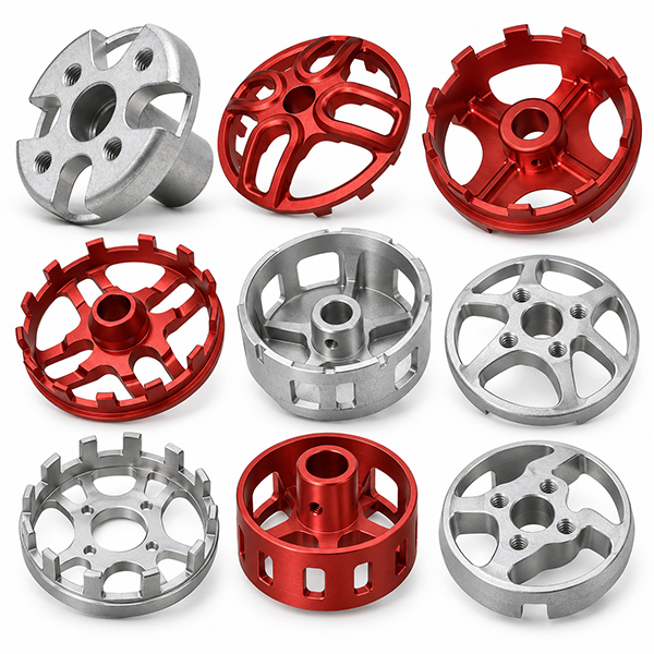
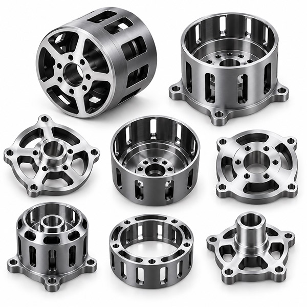
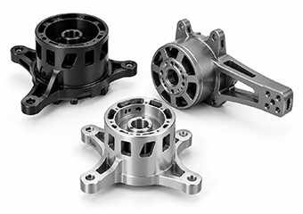
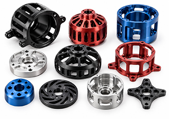
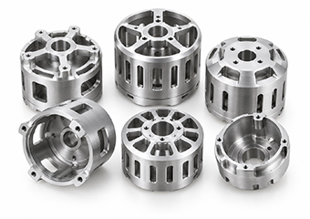
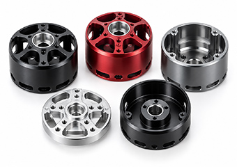
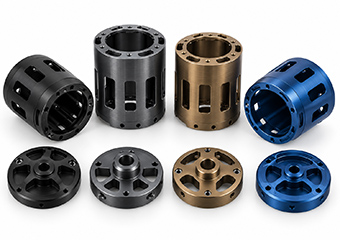
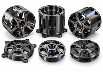
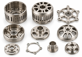
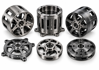
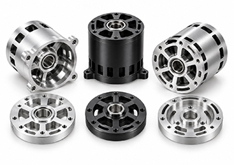
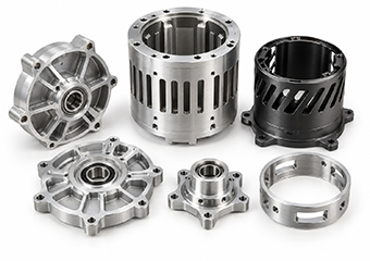
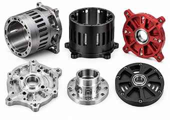
Custom CNC Drone Motor Housing Machining Services

Custom CNC Drone Motor Housing Machining Services

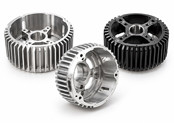
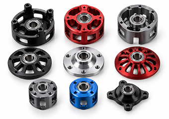
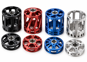
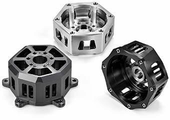
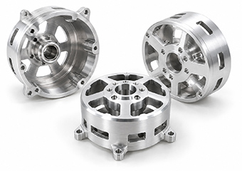
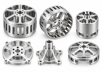
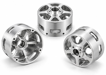
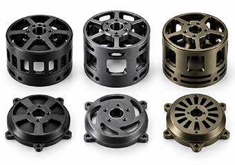
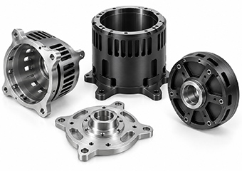
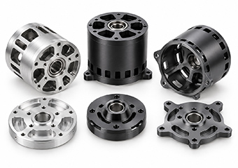
Custom CNC aluminum drone and UAV motor housings with DFM support for thin walls, bearing fits, concentricity, anodizing and inspection, from prototype to repeat production.

Product Specification:

  • Services : Custom CNC Drone Motor Housing Machining Services
  • Supply Ability : 100000 Pieces per Month
  • Material : Aluminum(AL 6061-T6, 6063, 7075-T6, 6082, 2024,etc), Magnesium Alloy, Titanium Grade 5, Customer's Demand.
  • Surface Roughness : Ra 0.1~3.2
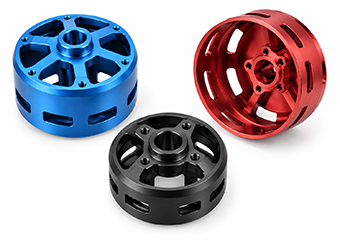
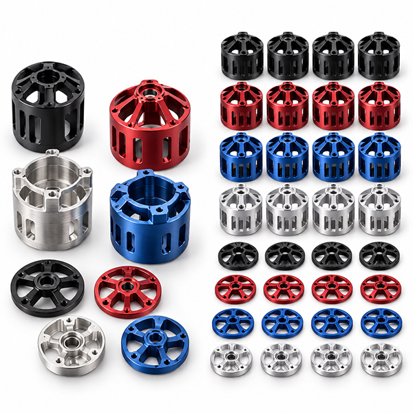
  • Surface Treatment : Customer's Demand, Type II Anodizing, Hard Anodizing, Bead Blasting + Anodizing, Polishing, Brushing, PVD Coating, Electroless Nickel Plating, Laser Marking etc.
  • Tolerance : ±0.005 mm.(Custom Available)
  • Drawing format : CAD file (dwg, dxf, pdf, etc.), 3D File (step, stp, etc), drawing design.
  • Standard or not : Non standard,customized as drawing or sample
Inquiry Now
Product description
Custom CNC Machining Solution

Custom CNC Drone Motor Housing Machining Solutions

VMT provides custom CNC machining solutions for aluminum drone and UAV motor housings based on your drawings, motor interfaces and production requirements. From thin-wall structures and bearing features to mounting datums, cooling geometry and post-finishing dimensions, our engineers review manufacturing risks before production and coordinate CNC machining, inspection and surface finishing from prototype validation to repeat production.

100+ CNC MachinesSupport prototypes, pilot runs and repeat production.
1-on-1 DFM SupportReview geometry, fits, datums and finishing risks before production.
12-Step Quality ControlIncoming, in-process and final quality checkpoints.
Prototype to ProductionValidate the design first, then transfer the approved process into repeat manufacturing.
Custom CNC Machining Drone Motor Housing
Functional Features First

Critical Features We Control in CNC Machined Drone Motor Housings

A drone motor housing is more than an aluminum shell. Bearing locations, motor interfaces, mounting datums, wall thickness and cooling features can directly affect assembly and mechanical performance. VMT plans machining sequences, fixture support and inspection around the functional features defined in your drawing.

01

Bearing Bores & Bearing Seats

Risk: Incorrect bore size, shoulder position or datum relationships can affect bearing installation and shaft alignment.

VMT Control: Bearing fits, bore depth, shoulders and related features are reviewed before machining. Turning, boring and inspection methods are selected according to your drawing, helping maintain a more predictable bearing fit and motor assembly.

02

Concentric & Coaxial Features

Risk: Re-clamping between turning and milling setups can shift the relationship between bearing bores, outside diameters and other circular features.

VMT Control: Where geometry allows, related circular features are machined from a common datum or reduced number of setups, then verified against the drawing to improve control of rotating and locating feature relationships.

03

Stator & Motor Assembly Interfaces

Risk: Incorrect pocket depth, shoulders, faces or threads can create interference or unwanted clearance during assembly.

VMT Control: Locating shoulders, internal pockets, mounting faces and threaded features are reviewed as one functional system rather than isolated dimensions, so the machining and inspection plan follows the actual motor assembly interfaces.

04

Thin Walls & Lightweight Structures

Risk: Reduced wall thickness and heavy material removal can lower rigidity and increase distortion during machining and after unclamping.

VMT Control: Material removal, fixture support, clamping position, machining allowance and finishing order are planned according to the housing geometry, helping balance UAV weight targets with manufacturability and dimensional stability.

05

Cooling Fins & Heat-Dissipation Features

Risk: Thin fins, narrow grooves and ventilation features can create tool-access, burr and deformation problems.

VMT Control: Feature depth, cutter access, edge conditions and machining sequence are reviewed before production so cooling geometry can be machined without unnecessarily affecting nearby bearing, mounting or mating features.

06

Mounting Datums, Holes & Threads

Risk: Incorrect hole positions or datum relationships can prevent the motor housing from locating correctly in the UAV assembly.

VMT Control: Mounting faces, bolt patterns, threads and locating features are planned from the drawing datum structure and checked during production, supporting repeatable positioning during final motor and frame assembly.

DFM Before Cutting

DFM Review Before CNC Machining Your Drone Motor Housing

Many motor housing problems begin before the first cutting operation. Wall thickness, bearing fits, datum relationships, tool access and anodizing requirements can all influence machining stability and final assembly. VMT reviews your drawing and 3D model before production to identify manufacturing risks and discuss practical machining options with your engineering team.

Wall Thickness & Lightweight PocketsReview rigidity, deep cavities, material removal and potential deformation.
Bearing & Assembly FitsReview seats, locating shoulders and mating interfaces together.
Datum & Tolerance RelationshipsIdentify which features should be machined or inspected together.
Tool Access & Internal GeometryCheck deep bores, narrow slots, internal corners and tool reach.
Cooling Fins & Small FeaturesEvaluate cutter size, feature rigidity, burr risk and machining direction.
Anodizing Allowance & MaskingIdentify close-fit, threaded, grounding and mating areas before finishing.
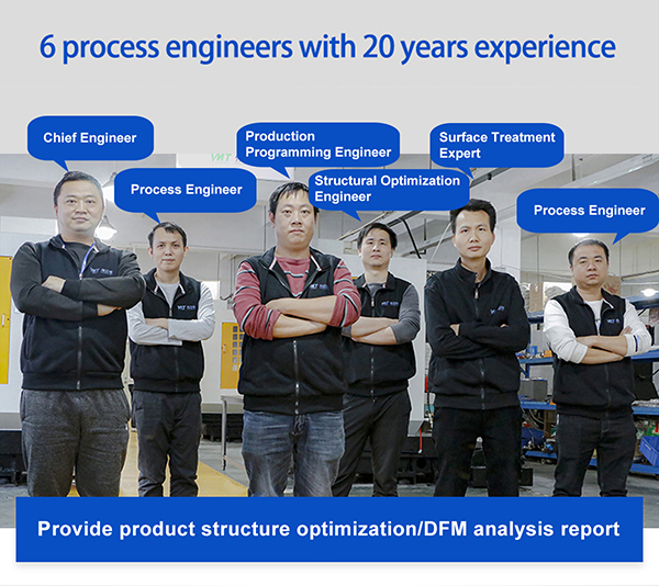
6 People with 20 Years of Experience in DFM Analysis Engineering Support
Process Selection by Geometry

CNC Machining Strategies for Custom Drone Motor Housings

Every motor housing VMT machines is custom-made from your drawing. Because the geometry, datums, wall thickness, bearing fits, mounting features and finishing requirements differ from part to part, the CNC machining route is developed specifically for each design. Turning, milling, multi-axis machining, fixture planning and inspection are combined only where the structure and functional requirements call for them.

Custom CNC Turning Manufacturing Services

CNC Turning for Circular Features

Suitable for cylindrical housings, bearing seats, internal and external diameters, shoulders and other rotational features. Related circular features can be planned around a common datum where the structure allows.

View CNC Turning Services →
CNC Milling Services

CNC Milling for Mounting & Functional Features

Used for bolt patterns, flats, mounting faces, connector openings, slots, pockets and lightweight structures. Machining order is planned around the functional datum structure in your drawing.

View CNC Milling Services →
5 Axis CNC Machining Parts Services

Multi-Axis Machining for Complex Geometry

For multi-sided, angled or access-limited features, multi-axis machining can reduce unnecessary repositioning and improve tool access when the drawing and part structure justify it.

View 5-Axis CNC Machining →
CNC Milling and Turning Composite Machining

Fixture & Machining Sequence Optimization

Roughing, semi-finishing, fixture support, clamping position and final machining are planned around thin walls, bearing areas and drawing-defined critical features.

Request a Machining Review →
Functional Inspection Plan

Critical Dimensions and Inspection for Drone Motor Housings

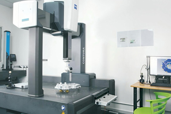
Inspection should follow the functional requirements of the motor housing rather than treating every dimension as equally critical. VMT identifies drawing-defined bearing features, mounting datums, hole positions, wall-related dimensions and assembly interfaces for in-process and final verification.

Critical Dimension and CMM Inspection for Precision CNC Drone Motor Housing
Bearing Bores & Seats Heavy stock removal or fixture pressure can change the bore after release, causing a bearing fit that is tight, loose or misaligned even when earlier in-process measurements looked acceptable. Major material removal is completed before final bearing finishing where the structure requires it. Bore diameter, shoulder depth and datum relationship can be checked with bore measurement and CMM methods. Suitable critical diameters can be reviewed to ±0.005 mm after engineering review.
Concentric / Coaxial Features Moving a housing from turning to a secondary milling setup, or re-clamping a thin cylindrical body, can shift the axis relationship between the bearing bore, OD and other rotating features. Related circular features are kept on a common datum or reduced number of setups where possible, then verified by CMM, runout or suitable axis-related inspection. In a published VMT aluminum motor-housing project, concentricity was controlled within 0.01 mm.
Motor & Stator Interfaces Pocket depth, locating shoulders and mating diameters can stack together and create interference, excessive clearance or incorrect axial location during motor assembly. DFM identifies the functional datum chain before machining. Pocket depth, locating diameters, shoulders and mating features are checked against the assembly drawing, with critical dimensions included in the agreed inspection plan.
Mounting Faces & Datums Thin sections can move after unclamping, changing flatness or the relationship between a mounting face and the motor axis. VMT uses staged roughing/finishing, controlled fixture support and free-state reinspection where required. Flatness, perpendicularity and datum relationships are measured to the drawing-specific GD&T requirement.
Hole Patterns & Position A secondary setup can shift bolt-hole true position relative to the primary bearing or mounting datum, creating assembly mismatch even when every hole diameter is correct. Hole patterns are programmed and inspected from the drawing datum structure. CMM or suitable positional inspection is used for critical patterns, and 100% checking can be applied to agreed critical hole positions.
Threads Anodizing or coating can tighten internal threads, while damaged or undersized threads can stop final assembly. Critical threads can be protected during finishing where required and verified after processing with suitable GO/NO-GO thread gauges according to the drawing and inspection plan.
Thin-Wall Areas Deep pockets and low wall thickness reduce rigidity, so the released part can move after roughing or clamping. VMT has published a motor-housing case involving a 1 mm thin-wall structure. Material removal is staged, fixture pressure is controlled, and important dimensions are rechecked after release. Final method and acceptance values are confirmed from the housing geometry and drawing requirements.
Post-Finish Critical Areas Anodizing, plating or coating can change the effective size of bearing seats, mating diameters, grounding areas and threads. Masking, pre-finish allowance and post-finish inspection are planned together. The final acceptance condition is defined from the drawing so the supplier knows whether the critical dimension applies before or after finishing.
±0.005 mmMachining capability for suitable critical dimensions after engineering review.
12-Step QCIncoming, in-process and final control points.
CMM SupportFor suitable dimensional and positional verification.
Critical FeaturesInspection can follow the agreed drawing-based inspection plan.


Published VMT motor-housing reference: an aluminum high-speed micro-motor housing project reported concentricity within 0.01 mm, many machined dimensions within 8 μm and a 1 mm thin-wall section. These figures are case-specific reference results, not a blanket tolerance guarantee for every housing geometry. View the published motor housing case
Custom From Your Drawings

Custom Drone & UAV Motor Housing Configurations We Machine

Drone motor housings vary in geometry, motor architecture, cooling design and mounting method. VMT machines custom housings from your 2D and 3D drawings, with process planning based on the functional features of each design.

Custom CNC Machining Cylindrical Drone Motor Housings

Cylindrical Drone Motor Housings

For compact brushless motor assemblies where bearing bores, internal shoulders and external diameters must maintain stable relationships.

Request a Quote
Custom CNC Machining Lightweight Thin-Wall Drone Motor Housings

Lightweight Thin-Wall Motor Housings

For weight-sensitive UAV platforms where reduced wall thickness must be balanced with machining stability and assembly requirements.

Request a Quote
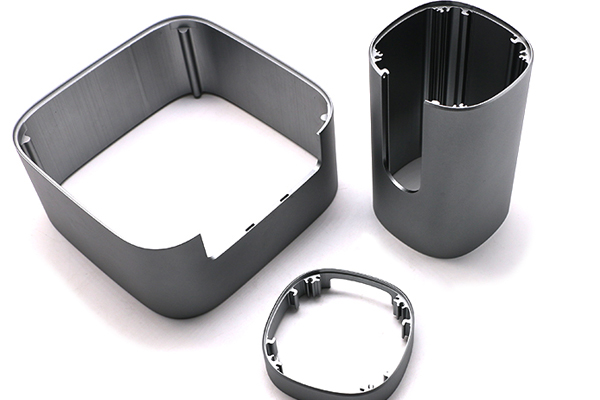
Custom CNC Machining Finned Aluminum Drone Motor Housings

Finned Aluminum Motor Housings

Cooling fins and grooves require attention to cutter access, fin rigidity, burr control and nearby functional dimensions.

Request a Quote
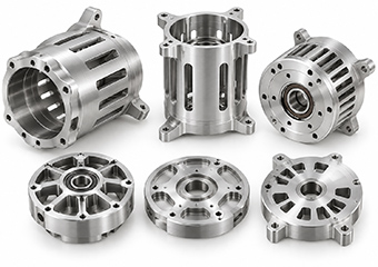
Custom CNC Machining Integrated Aluminum Drone Motor Housings and Mount Structures

Integrated Motor Housing & Mount Structures

Combines motor support with flanges, bosses, bolt patterns or locating surfaces that should be planned as one functional system.

Request a Quote
Custom CNC Machining Drone Motor Bearing End Housings & End Caps

Bearing End Housings & End Caps

Precision bores, shoulders, hole patterns and mating surfaces are controlled according to the motor assembly drawing.

Request a Quote
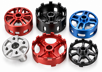
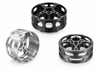
Custom CNC Machining Pocketed & Weight-Reduced Aluminum UAV Motor Housings and End Caps

Pocketed & Weight-Reduced Housings

Deep pockets, ribs and lightweight features reduce mass but can also change local rigidity during machining.

Request a Quote
Custom CNC Machining Multi-Sided UAV Motor Housings

Multi-Sided UAV Motor Housings

Connector openings, slots, cooling features and mounting details across several faces may benefit from reduced setup changes.

Request a Quote
Custom CNC Machining Drone Motor Housings Manufacturing From Your Drawings

Motor Housings From Your Drawings

For non-standard designs, VMT reviews your CAD model, interfaces, tolerances, material and quantity before defining the process.

Request a Quote
Material Selection

Material Selection for Custom Drone Motor Housings

Motor-housing material selection should balance five factors: lightweight design, heat dissipation, stiffness, machinability and surface finishing. Aluminum remains the most common choice for CNC drone motor housings, especially 6061 and 7075, but other grades or special materials may be considered when the application has different strength, thermal, corrosion or weight requirements.

6061-T6 Aluminum CNC Machining Drone Motor Housings

6061-T6 Aluminum

Balanced machinability, corrosion resistance, thermal performance and anodizing response make 6061-T6 a practical option for many consumer, industrial and prototype UAV motor housings.

Discuss 6061-T6
7075-T6 Aluminum CNC Machining Drone UAV Motor Housings

7075-T6 Aluminum

Higher strength and stiffness make 7075-T6 attractive for weight-sensitive, high-performance and higher-load UAV structures where the design justifies the additional material cost.

Discuss 7075-T6
6063 Aluminum CNC Machining Drone Motor Housings

6063 Aluminum

6063 is useful where surface appearance, anodizing quality and thermal performance are important and the structure does not require the same strength level as 7075.

Discuss 6063
6082 Aluminum CNC Machining Drone UAV Motor Housings

6082 Aluminum

6082 combines relatively high strength with good machinability and can be considered for industrial UAV housings, European projects and more heavily loaded structural motor components.

Discuss 6082
6061-T6 Aluminum General-purpose UAV housings Lightweight, easy to machine, good thermal performance, corrosion resistance and stable anodizing. Consumer, industrial and prototype drone motor housings.
7075-T6 Aluminum High strength-to-weight requirements Higher strength and stiffness; useful for thinner or more highly loaded structures. Finishing and corrosion protection should be reviewed with the application. High-performance, racing, aerospace-oriented and demanding UAV structures.
6063 Aluminum Appearance + heat dissipation Good thermal conductivity and excellent anodized appearance; lower structural strength than 7075. Visible housings, heat-dissipation-oriented housings and lighter-duty motor shells.
6082 Aluminum Industrial structural housings Good machinability with relatively high strength; commonly considered for structural applications and European material specifications. Industrial UAVs and higher-load structural motor housings.
2024 Aluminum Fatigue / aerospace-oriented requirements High strength and fatigue performance, but corrosion protection and finishing require more attention than 6061. Special aerospace or highly loaded projects after engineering review.
Magnesium Alloy Extreme weight reduction Very low density offers strong weight-saving potential, but machining safety, corrosion protection and finishing requirements are more demanding. Special ultralight projects subject to material/process review.
Titanium Grade 5 Special high-strength environments High strength and corrosion resistance, but higher material and machining cost make it less common for standard motor housings. Special aerospace or high-strength interfaces where aluminum is not suitable.
Finishing + Fit Control

Surface Finishing for Drone Motor Housings Without Losing Critical Fits

Surface finishing can affect more than appearance. Bearing seats, threads, grounding areas, mounting faces and precision mating interfaces may require masking, machining allowance or post-process inspection. VMT coordinates CNC machining and finishing around the functional areas identified in your drawing.

Type II Anodizing Aluminum Drone UAV Motor Housings CNC Machining

Type II Anodizing

Used for corrosion protection and cosmetic color. Bearing seats, threads and electrical-contact areas can be reviewed for masking or post-finish dimensional checks.

Discuss This Finish
Hard Anodizing Aluminum Drone UAV Motor Housings CNC Machining

Hard Anodizing

Suitable where increased hardness or wear resistance is required. Coating build-up must be considered around close fits, threads and mating diameters.

Discuss This Finish
Bead Blasting + Anodizing Aluminum Drone UAV Motor Housings CNC Machining

Bead Blasting + Anodizing

Creates a uniform matte appearance before anodizing. Cosmetic surfaces should be separated from bearing, locating and other precision interfaces in the process plan.

Discuss This Finish
Polishing + Anodizing Aluminum Drone UAV Motor Housings CNC Machining

Polishing + Anodizing

Used when a brighter or more refined visible surface is required. Polishing direction, edge condition and dimensional interfaces should be reviewed before anodizing.

Discuss This Finish
Brushing + Anodizing Aluminum Drone UAV Motor Housings CNC Machining

Brushing + Anodizing

Provides a directional cosmetic texture before anodizing. Visible surfaces, edge transitions and functional contact areas should be defined on the drawing.

Discuss This Finish
PVD Coating Aluminum Drone UAV Motor Housings CNC Machining

PVD Coating

PVD can be considered for selected appearance, wear or functional requirements. Base-material preparation and protected fit areas must be reviewed before coating.

Discuss This Finish
Electroless Nickel Plating Aluminum Drone UAV Motor Housings CNC Machining

Electroless Nickel Plating

Provides a uniform deposited coating for selected corrosion, wear or appearance requirements. Plating thickness must be considered around precision bores and mating features.

Discuss This Finish
Laser Marking CNC Machining Aluminum Drone UAV Motor Housings

Laser Marking

Part numbers, logos, batch codes and assembly identification can be added after machining and finishing without changing the core housing geometry.

Discuss This Finish
Critical Areas Reviewed Before Surface Finishing: bearing bores, threads, mounting faces, electrical-contact areas, mating surfaces and precision locating features may require masking, allowance or post-finish verification depending on the drawing requirements.
Prototype → Validation → Production

From Drone Motor Housing Prototype Validation to Repeat Production

A successful prototype proves more than whether the part can be machined. It also allows your engineering team to verify assembly fit, bearing interfaces, mounting locations, wall stability and surface finishing before the manufacturing process is transferred into repeat production.

Stage 01

Prototype Machining

Initial parts can verify overall geometry, motor fit, bearing installation, mounting interfaces, machining access and surface finish before larger quantities are released.

Stage 02

Engineering Validation

Feedback from prototype assembly or functional testing can be incorporated into the drawing, machining sequence, fixture concept, finishing requirements and inspection plan.

Stage 03

Repeat Production

After design and process approval, VMT follows the confirmed machining, finishing and inspection requirements to support more consistent repeat manufacturing.

Still Testing Your Motor Housing Design?


You do not need to finalize mass production before contacting us. Send your current CAD model, prototype quantity and critical interfaces, and our engineers can review machining risks before you release the design.


Custom Drone Motor Housing Prototype Validation to Repeat CNC Production
UAV Application Context

Custom CNC Motor Housings for Drone & UAV Applications

Motor housing requirements change with aircraft size, payload, operating environment and propulsion architecture. VMT supports custom CNC machined motor housings based on your motor design, mounting structure, weight target, material and production requirements.

Custom CNC Machining Motor Housings for Agricultural & Crop Protection Drones

Agricultural & Crop Protection Drones

Balance weight, rigidity, corrosion protection and repeated field operation around the actual propulsion and mounting design.

Discuss This Application
Custom CNC Machining Motor Housings for Industrial Inspection UAVs

Industrial Inspection UAVs

Custom housings for propulsion systems used around infrastructure, factories and remote inspection environments.

Discuss This Application
Custom CNC Machining Motor Housings for Mapping & Surveying UAVs

Mapping & Surveying UAVs

Lightweight housings can support aircraft designed around flight efficiency, payload management and mission duration.

Discuss This Application
Custom CNC Machining Motor Housings for Imaging & Photography Drones

Imaging & Photography Drones

Compact motor housings can be machined for weight-sensitive platforms with controlled motor and mounting interfaces.

Discuss This Application
Custom CNC Machining Motor Housings for Logistics & Delivery UAVs

Logistics & Delivery UAVs

Higher-payload platforms may place greater demands on motor and mounting structures, increasing the importance of material, stiffness and interface design.

Discuss This Application
Custom CNC Machining Motor Housings for Non-standard Electric Propulsion Systems

Custom Electric Propulsion Systems

VMT also supports non-standard electric propulsion housings that do not fit conventional drone motor configurations.

Discuss This Application
Published VMT Case Study

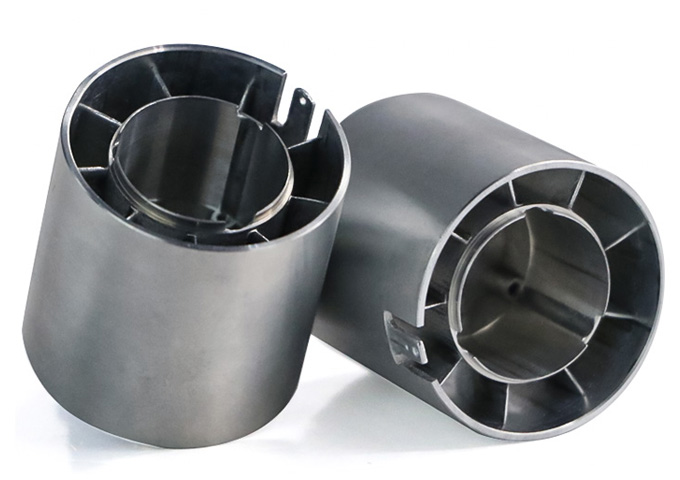
Case Study: CNC Machining 6061 Aluminum High-Speed Micro Motor Housing

VMT manufactured this 6061 aluminum high-speed micro motor housing using die casting and CNC machining for a 60,000-piece production project. The part required tight control of 1 mm thin-wall stability, bearing-related concentricity and micron-level dimensions—manufacturing challenges that are also common in many drone and UAV motor housing projects.

CNC Machining 6061 Aluminum High-Speed Micro Motor Housing Case Study
6061 Aluminum · Die Casting + CNC Machining

Critical Requirements: 8 μm Dimensions, 0.01 mm Concentricity and 1 mm Thin Walls

The housing required many machined dimensions to remain within 8 μm, while concentricity had to be controlled within 0.01 mm. The structure also included a 1 mm thin-wall area, making fixture pressure, material removal and final machining sequence especially important.

≤ 8 μm Many machining dimensions specified within this range in the published project.
≤ 0.01 mm Concentricity requirement for the motor housing.
1 mm Thin-wall structure requiring deformation and clamping control.
60,000 pcs Published production quantity for the project.

Manufacturing Challenge

For a high-speed motor housing, dimensional error or poor concentricity can affect rotating alignment and contribute to noise or assembly problems. The combination of micron-level dimensions, 0.01 mm concentricity and a 1 mm thin wall made process stability the main challenge.

VMT Process Control

The part used a die-cast near-net shape followed by CNC machining to reduce unnecessary full-stock machining. VMT then spent 10 days testing and adjusting the machining process before completing the first batch, with particular attention to thin-wall deformation and concentric features.

Production Result

The published project lists a 35-day delivery time for 60,000 pieces. The first batch was completed after process validation, and the customer confirmed the delivered result. The case demonstrates a production route that combined cost control, precision machining and repeat-volume manufacturing.

Published VMT Customer Feedback

What Customers Say About Working with VMT

These published VMT customer comments are not presented as drone-motor-housing-specific orders. They are selected because they address the same supplier concerns that matter in a precision motor housing project: tolerance control, machining quality, prototype approval, packaging, communication and confidence to continue into production.

Customer Feedback – Tolerance and Machining Quality
Tolerance & Machining Quality
“The parts arrived in perfect condition. The tolerances were respected, the machining looked excellent, and the team did a great job.”

Published VMT machining customer feedback

Customer Feedback – Prototype Approval and Production Confidence
Prototype Approval & Production Confidence
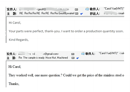
“Your parts were perfect, thank you. I want to order a production quantity soon.”

Published VMT machining customer feedback

Customer Reviews – Packaging Workmanship and Communication
Packaging, Workmanship & Communication
“The parts arrived perfect, every part was securely packed, and the workmanship and communication were top notch. We look forward to more business together.”

Published VMT machining customer feedback

FAQ

Frequently Asked Questions About Custom CNC Drone Motor Housings

Open each question to review the machining, material, finishing and prototype considerations before sending your motor housing drawing for quotation.

QCan VMT CNC machine custom drone motor housings from my drawings?
A

Yes. VMT provides custom CNC machining based on your 2D drawings, 3D models, material, tolerance, surface finish and quantity requirements. Our engineers can review bearing interfaces, thin walls, mounting features and critical dimensions before production.

QWhich aluminum is suitable for a drone motor housing, 6061 or 7075?+
A

6061 is commonly considered when machinability, corrosion resistance, thermal performance and manufacturing efficiency are important. 7075 may be selected where higher strength-to-weight performance is required. The correct choice depends on structural load, wall thickness, weight target and finishing requirements.

QHow do you control thin-wall deformation during CNC machining?+
A

Thin-wall stability depends on geometry, material removal, clamping and machining sequence. VMT reviews the structure before production and can use staged roughing, controlled machining allowance, fixture support and final finishing according to the actual housing design.

QCan you machine precision bearing bores?+
A

Yes, where required by the drawing. Bearing bores, shoulders and related circular features are reviewed together with their datum and fit requirements. In a published VMT aluminum motor-housing project, concentricity was controlled within 0.01 mm; the achievable value for your part depends on geometry, size, datum strategy and inspection method.

QCan anodizing affect bearing fits and assembly dimensions?+
A

Yes. Anodizing can affect close-fit areas depending on the finishing specification. Bearing seats, threads, grounding areas and precision mating surfaces should therefore be identified before finishing so masking, machining allowance and post-finish inspection can be planned.

QCan VMT machine cooling fins and lightweight pockets?+
A

Yes, depending on geometry and tool accessibility. VMT reviews feature depth, remaining wall thickness, cutter access, corner radii and machining direction before production so non-critical complexity does not unnecessarily increase cost or deformation risk.

QCan I order prototypes before repeat production?+
A

Yes. Prototype machining can be used to verify motor fit, bearing interfaces, mounting locations, machining feasibility and finishing requirements before larger quantities are released. Assembly feedback can then be incorporated into the drawing and production route.

QWhat information should I send for a quotation?+
A

Send your 2D or 3D drawing together with the required material, critical tolerances, surface finish, quantity and inspection requirements. If available, also indicate bearing interfaces, mounting datums, mating features and any masking requirements.

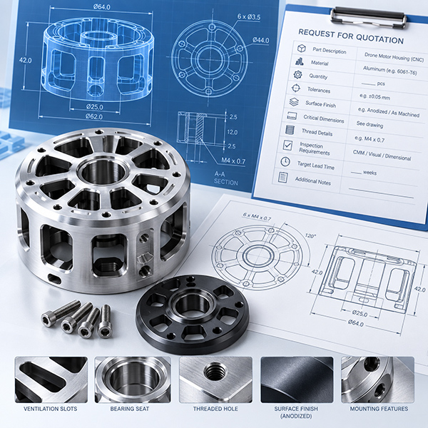
Make the RFQ Easier

What Should You Send Us for a Custom Drone Motor Housing Quote?

You do not need to prepare a long specification document before contacting VMT. A current drawing or CAD model together with the key manufacturing requirements is usually enough for our engineering team to begin reviewing the project.

1. 2D Drawing / 3D CAD
Use the latest revision.
2. Aluminum Grade
6061, 7075 or another specified alloy.
3. Critical Fits & Datums
Mark bearing and assembly-critical features.
4. Surface Finish
Include anodizing, masking or cosmetic requirements.
5. Quantity
Prototype, pilot batch or repeat production.
6. Inspection Requirements
Include special reports or assembly checks.
Custom CNC Drone Motor Housing Drawing CAD Model and RFQ Requirements
Long-Form Engineering Resource

Engineering Guide to Custom CNC Aluminum Drone Motor Housing Machining

Designing and manufacturing a drone motor housing requires balancing weight, structural rigidity, bearing alignment, motor interfaces, cooling features and surface finishing within a compact component. Many production problems do not come from a single difficult tolerance; they come from interactions between thin walls, heavy material removal, multiple setups, bearing features and post-machining finishing.

A useful motor housing drawing therefore needs to define not only nominal dimensions but also which features control motor assembly, which surfaces establish datums, which areas require finishing protection, and which characteristics must remain stable from prototype through repeat production.

1. Start With the Functional Interfaces, Not With Every Dimension

One of the most common mistakes when designing a CNC motor housing is treating every dimension as equally important. For a drone motor housing, bearing bores, bearing shoulders, stator locating features, shaft-related centerlines, mounting faces, bolt-hole patterns, mating diameters and critical threaded interfaces usually have much greater functional importance than cosmetic or non-mating geometry.

The first engineering question should be: Which features actually determine whether the motor can be assembled and operate correctly? Once those features are identified, their datum relationships can be reviewed before defining the machining route.

Engineering Note: a bore diameter can be individually correct while its relationship to another axis, face or hole pattern is not adequate for the final assembly. Size tolerance and feature relationship are not the same requirement.

What VMT Reviews

  • Which dimensions are assembly-critical.
  • Which surfaces should act as primary references.
  • Which features should preferably be machined in the same setup.
  • Whether repeated repositioning may increase tolerance accumulation.
  • Which dimensions need in-process verification instead of final inspection only.

This reduces the risk of producing a part that meets isolated dimensions but still creates problems during bearing installation, motor assembly or final UAV integration.

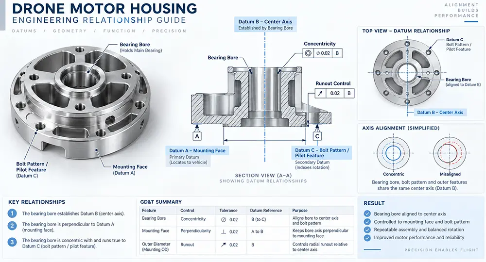
CNC Machining Drone Motor Housing Bearing Bore and Machining Datum Relationship Guide

2. How Bearing Bores Should Be Considered in a Drone Motor Housing

Bearing features are often among the most important areas in a motor housing. The challenge is not simply producing a precise hole. The housing may include one or more bearing bores, axial shoulders, snap-ring grooves, mating diameters, end-cap interfaces and shaft-related features that must maintain controlled relationships.

Why Bearing Fits Can Change

Material removal: when large volumes of material are removed around a bearing area, the remaining structure becomes less rigid. Final bore geometry can behave differently before and after surrounding pockets are machined.

Clamping: a thin housing can deform under fixture pressure. A bore that measures correctly while constrained may move after release.

Machining sequence: if a precision bearing feature is finished too early and major material removal happens later, stress redistribution can affect the already-finished area.

Surface finishing: anodizing or another finish can change the effective condition of a close-fit interface if masking or dimensional allowance has not been considered.

Process Logic to Review

  1. Rough the main housing structure.
  2. Leave machining allowance around critical areas where appropriate.
  3. Establish stable reference surfaces.
  4. Complete major secondary material removal.
  5. Finish bearing-related features later in the sequence where the geometry requires it.
  6. Verify drawing-defined critical relationships.
  7. Protect or mask selected interfaces during finishing where required.
  8. Perform the agreed final checks.

The drawing should identify the actual bearing fit, datum relationship, shoulder depth, mating surfaces and whether the final requirement applies before or after surface finishing.

3. Thin-Wall Motor Housings: Weight Reduction vs. Machining Stability

Weight reduction is a clear priority in UAV design, but removing aluminum also removes stiffness. A housing that appears rigid as a solid CAD model can behave differently after deep pockets, windows, thin cylindrical walls, ribs and cooling slots are machined.

Four Common Deformation Mechanisms

Cutting force: a thin wall can deflect away from the cutter, especially when long tools or heavy engagement are required.

Clamping force: the fixture itself can deform the housing before machining starts.

Uneven material removal: removing a large volume from one region first can change the balance and rigidity of the part.

Residual stress: material can contain residual stress that becomes more visible as stock is removed.

Manufacturing Controls to Consider

  • Staged roughing and finishing.
  • Balanced material removal.
  • Temporary support material where geometry allows.
  • Controlled clamping locations and force.
  • Finishing allowance for critical areas.
  • Finishing critical dimensions later in the sequence.
  • Rechecking important dimensions after unclamping.
Design point: the lightest possible wall is not automatically the best design. The target should be the required weight with a structure that can still be machined, inspected and repeated reliably.

4. Why Datum Planning Matters More Than Adding More Tight Tolerances

When a motor housing has multiple precision features, tightening every tolerance is not automatically a reliable way to improve assembly. It can increase machining and inspection cost without clarifying which feature relationships actually control function.

Separate the drawing into three groups: functional critical features that directly influence bearing, shaft, motor or mounting performance; assembly-clearance features that mainly need enough clearance; and cosmetic or non-critical features that primarily affect appearance or packaging.

During DFM Review, Check Whether:

  • Critical relationships are clearly identified.
  • Datum references are practical to machine and inspect.
  • Related features can be machined in one setup.
  • Tolerance requirements match the functional need.
  • Critical dimensions should be checked during machining rather than only at final inspection.

5. Cooling Fins, Slots and Heat-Dissipation Geometry

Fins, grooves and openings can support thermal management and weight reduction, but they also create difficult machining conditions. Very thin fins may vibrate, deep narrow grooves can require long-reach tools, small internal radii require smaller cutters, and densely spaced fins can reduce chip evacuation space.

DFM Questions to Ask

  • Does every fin need the same thickness?
  • Can the internal corner radius be increased?
  • Does the groove need to be as deep as designed?
  • Can tool access be improved?
  • Can a hidden cosmetic feature be simplified without changing function?
  • Is the minimum wall thickness driven by a real engineering requirement?

6. CNC Turning, Milling and Multi-Axis Machining: Which Process Should Be Used?

A drone motor housing may require more than one CNC process. Turning is efficient for rotational features such as bearing bores, shoulders and concentric internal/external geometry. Milling is typically used for bolt patterns, mounting flats, slots, windows, pockets and non-rotational details.

Multi-axis machining becomes useful when features are distributed across several orientations or when tool access becomes difficult. The question is not whether a more advanced machine can be used; it is whether reducing repositioning or improving access helps control the required geometry and production risk.

For some housings, turning plus milling is the practical route. For others, multi-axis machining reduces setup changes. The process should follow the drawing and part structure.

7. Surface Finishing Must Be Planned Before Final Machining

Anodizing is common on aluminum UAV components, but it should not be treated as an unrelated operation added after CNC machining. Bearing fits, threads, electrical-contact surfaces, grounding areas, mounting faces and locating diameters may need special consideration.

When a drawing contains a critical dimension, the supplier needs to understand whether that requirement applies before or after finishing. For close-fit interfaces, do not assume one universal correction for anodizing; the finishing specification, masking requirement, dimensional allowance and final inspection condition should be coordinated together.

Areas That May Need Masking

  • Precision bearing seats.
  • Selected threads.
  • Grounding or electrical-contact surfaces.
  • Locating surfaces.
  • Tight mating diameters.

8. Threaded Features Need to Be Reviewed Together With Finishing

Motor housings can contain small threaded mounting holes, inserts, cable interfaces or sensor connections. A thread that functions correctly before finishing may behave differently after anodizing if the surface condition changes the effective thread fit.

Possible Engineering Options

  • Mask selected threads where required.
  • Use a suitable pre-finish allowance when appropriate.
  • Verify or chase threads after finishing only when the specification allows it.
  • Use thread gauges as part of final inspection.
  • Add inserts after finishing for suitable assemblies.

9. Prototype Validation Should Include More Than Dimensional Inspection

A prototype motor housing should answer more than whether the individual dimensions match the drawing. It should also confirm bearing installation, motor assembly fit, mounting-hole accessibility, mating with the UAV structure, connector position, surface-finish influence on assembly, cosmetic expectations and tool access during final assembly.

Recommended validation loop: prototype → assembly feedback → drawing revision → manufacturing process update → production approval → repeat production.

10. How to Define an Inspection Plan for a Drone Motor Housing

Inspection should be based on feature function. Bearing features, hole patterns, mating surfaces, profiles and cosmetic zones may need different measurement methods and acceptance criteria.

Bearing Features

Review bore diameter, shoulder location, depth and the drawing-defined relationship to other datums.

Hole Patterns

Check hole location, spacing, thread specification and mounting relationship from the defined datums.

Mating Surfaces

Verify the dimensions and geometric relationships required by the drawing.

Complex Profiles

CMM or other suitable dimensional inspection can be considered where multiple feature relationships must be verified.

Cosmetic Surfaces

Visible surfaces should have clearly defined appearance criteria separate from dimensional criteria.

Inspection principle: the inspection plan should be defined before machining, not created only after the finished part reaches final QC.

11. What Actually Drives the Cost of a CNC Drone Motor Housing?

A small motor housing is not automatically inexpensive. Cost is driven by manufacturing complexity, including material removal, number of setups, wall thickness, tolerance relationships, tool accessibility, finishing requirements and inspection effort.

Main Cost Drivers

  • Material removal ratio: large billet-to-finished-part reduction increases material and machine time.
  • Number of setups: each setup adds handling, alignment and process-control effort.
  • Tight tolerances: critical requirements can require slower finishing and additional inspection.
  • Tool access: deep or narrow features may need smaller or longer tools.
  • Surface finishing: masking, cosmetic control and post-finish inspection add steps.
  • Inspection: more critical characteristics increase measurement time.
  • Production quantity: fixture and process decisions differ between prototypes and repeat production.

Ways to Reduce Unnecessary Cost

  • Relax non-critical tolerances where function allows.
  • Increase internal radii where possible.
  • Avoid unnecessary ultra-thin walls.
  • Simplify hidden cosmetic features.
  • Reduce unnecessary setup orientations.
  • Clearly identify which surfaces require premium cosmetic finishing.

12. What Should Be Included in a Drone Motor Housing RFQ?

A clear RFQ shortens engineering review and reduces unnecessary assumptions. Include the latest 3D model, 2D engineering drawing, material, surface finish, quantity and inspection requirements.

  • 3D CAD model: STEP or another suitable neutral format for geometry review.
  • 2D drawing: datums, critical tolerances, threads, surface finish and special notes.
  • Material: specify alloy and temper when already defined.
  • Surface finish: anodizing type, color, masking and cosmetic expectations.
  • Critical assembly features: mark bearing fits, mating surfaces and locating interfaces.
  • Quantity: separate prototype, pilot and expected repeat-production quantities.
  • Inspection: identify required dimensional or first-article documentation.
  • Mating-part information: provide it where an interface needs additional context.

13. Final Engineering Checklist Before Releasing the Drawing

  • Are the bearing fits clearly defined?
  • Are important datums identified?
  • Are critical assembly dimensions separated from cosmetic dimensions?
  • Have unnecessary tight tolerances been removed?
  • Are thin-wall areas actually required by weight targets?
  • Can cutters access deep pockets and cooling grooves?
  • Are practical internal corner radii provided?
  • Are anodized and non-anodized areas defined?
  • Are threads affected by finishing requirements?
  • Do critical dimensions apply before or after finishing?
  • Is the prototype quantity specified?
  • Are expected production quantities available?
  • Are special inspection reports required?
  • Are visible cosmetic surfaces clearly identified?
Request a DFM Review

Related suggestion

Write us

Give us a call or send an inquiry to our emailbox, we will answer your doubts according to your customers' requirements, and quote you immediately.

Upload 2D/3D drawings

Upload Your Files or Contact inquiry@vimetal.com.cn to Get Instant Quote (Please attach 2D CAD drawings and 3D CAD models in any format including STEP, IGES, DWG, PDF, STL, ZIP, etc.).
Upload files ( Max file size: 20MB )

Upload 2D/3D drawings

Upload Your Files or Contact inquiry@vimetal.com.cn to Get Instant Quote (Please attach 2D CAD drawings and 3D CAD models in any format including STEP, IGES, DWG, PDF, STL, ZIP, etc.).
Upload files ( Max file size: 20MB )
+86 15099911516
loading