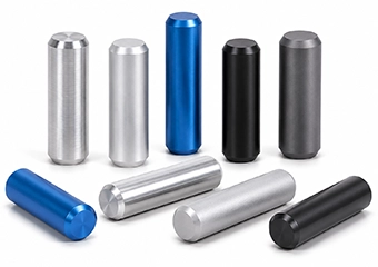
Straight Aluminum Dowel Pins
Straight aluminum dowel pins locate plates, housings and fixtures; CNC turning controls the functional OD, length and lead-in geometry so the pin matches your specified mating-hole fit.

Home / Product / Industrial Industry /
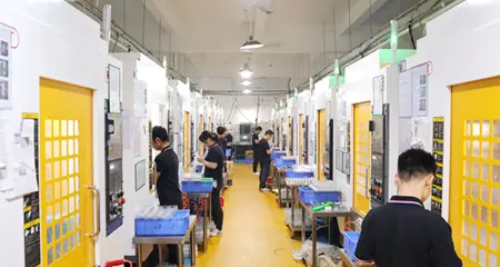
VMT is a manufacturing facility for various industrial CNC machining parts. With 16 years of experience in CNC processing industrial parts and various types of CNC industrial parts samples, you can send pictures to view and view the factory online, contact us immediately to obtain samples. We can provide you with various types of industrial CNC machining product services to meet your customized CNC machining needs.
Product Specification:


We manufacture custom aluminum dowel pins, locating pins and drawing-specific precision pins for engineers and OEM buyers who need reliable fit, alignment and repeatable assembly. Before machining, we review the locating diameter, mating hole, fit type, alloy, secondary features and finished condition so the pin is manufactured around the assembly requirement.
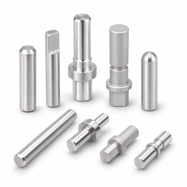
Are you dealing with dowel pins that press in too tightly, locate too loosely, bind during assembly, or lose their intended fit after anodizing? Do you need a non-standard aluminum pin with stepped diameters, shoulders, threads, grooves, flats or cross holes?
We manufacture custom aluminum dowel and locating pins from your drawings for prototype validation and repeat production. CNC turning, Swiss machining and secondary milling or drilling are selected around the functional diameter, shoulder position and secondary features that control locating and assembly performance.
For suitable critical dimensions, our CNC machining capability can reach tolerances as tight as ±0.005 mm after engineering review. Combined with 12-step quality control and finished-condition inspection, we help reduce fit variation, assembly rework and repeat-production risk.
Discuss Your Dowel Pin RequirementFor suitable critical locating dimensions, our CNC machining capability can reach tolerances as tight as ±0.005 mm after engineering review. Reliable positioning still depends on the complete tolerance chain—not the pin diameter alone.
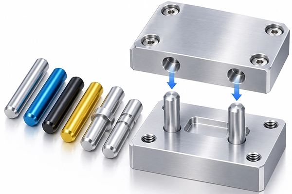
Excess interference can increase press-in force, damage the mating hole, gall contact surfaces or distort softer aluminum features. We review the finished pin OD, mating-hole tolerance and finish condition together before confirming the machining target.
Too much clearance can reduce repeatable positioning even when assembly feels easy. We review the locating function, finished pin diameter and mating-hole tolerance to balance assembly clearance with positioning repeatability.
Two round locating pins can over-constrain an assembly when center distance and mating-hole position tolerances stack in opposite directions. Where appropriate, we review the secondary locating feature and available clearance strategy.
A close-fitting pin entering a blind hole can compress trapped air and prevent full seating. Where the assembly requires it, we review vent flats, grooves or relief features before machining.
Anodizing, plating, polishing and other finishing operations can change the final locating diameter. Critical pin and hole dimensions are therefore reviewed in the finished condition, with masking, allowance or post-finish inspection where necessary.
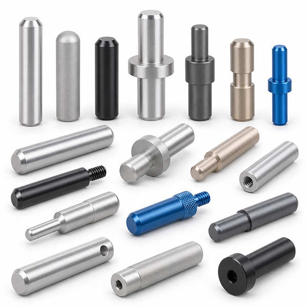
From straight and stepped pins to shouldered, threaded, vented and cross-drilled designs, we machine each aluminum pin around its locating, retention, removal or alignment function. CNC turning establishes the critical cylindrical features, while secondary milling and drilling add flats, holes or slots while preserving their relationship to the locating datum.
Straight aluminum dowel pins locate plates, housings and fixtures; CNC turning controls the functional OD, length and lead-in geometry so the pin matches your specified mating-hole fit.
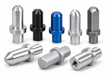
Precision locating pins establish repeatable position between components; we machine the locating diameter and datum-related features to your drawing, then inspect the dimensions that control assembly.
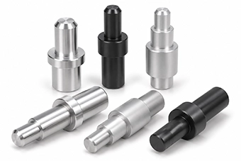
Stepped dowel pins combine installation, locating or clearance diameters; CNC turning keeps the step diameters and shoulder positions related so each section performs its intended assembly function.
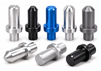
Shouldered locating pins provide radial location and an axial stop; we control the locating OD, shoulder position and transition geometry so the pin seats against the intended assembly reference.
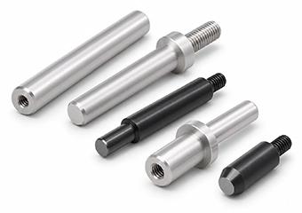
Threaded and pull-out pins support removal, retention or servicing; we machine the locating diameter and thread as one functional component so extraction features do not compromise positioning.
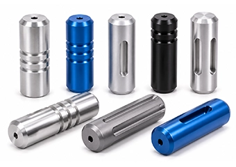
Vented and grooved pins support blind-hole installation or drawing-specific relief; we add flats or grooves only where the assembly needs them while protecting the usable locating surface.
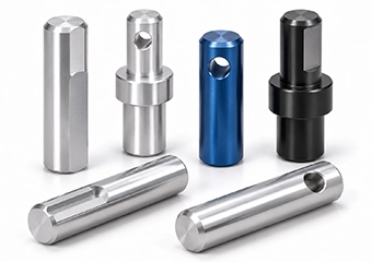
Pins with flats, slots or cross holes add orientation, anti-rotation or attachment functions; turning establishes the cylindrical datum before secondary milling or drilling positions the added feature.
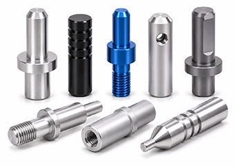
Custom precision pins combine non-standard diameters, shoulders, threads, grooves, radii or holes; we build the machining sequence around the drawing so functional relationships stay controlled.
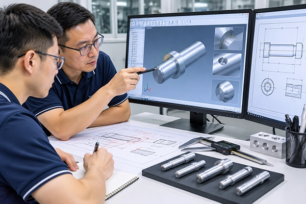
We use DFM to turn assembly requirements into a machining and inspection plan before production. The review covers the fit relationship, material condition, machining route, finishing allowance and the critical dimensions that need to be verified in the finished part.
| Engineering Review | What Can Fail | What We Actually Do | Verifiable Result |
|---|---|---|---|
| Pin-to-Hole Fit | The pin passes OD inspection but still presses too tightly or locates too loosely. | We review the pin tolerance, mating-hole tolerance and fit requirement together, then confirm whether the critical diameter is controlled before or after finishing. | First article verifies the locating diameter used for the actual assembly condition. |
| Material & Stock Condition | Material movement after stock removal changes final OD, straightness or shoulder position. | We confirm alloy, temper and stock form, then plan roughing and finishing around material removal and geometry. | Critical dimensions are rechecked after the machining sequence has released the part. |
| Long / Slender Geometry | Deflection or vibration creates taper, chatter or unstable diameter. | We review length-to-diameter ratio and select conventional turning, Swiss machining or additional support according to the geometry. | The machining route is selected around stability instead of using the same setup for every pin. |
| Secondary Features | Cross holes, flats or slots lose position relative to the locating OD. | We establish the cylindrical datum first, transfer that datum into secondary milling or drilling and inspect the feature position relative to the turned reference. | Secondary features remain related to the same locating datum used in assembly. |
| Anodizing / Plating | Coating changes the final OD, thread or shoulder fit. | We identify critical areas before finishing, define allowance or masking where required and recheck critical dimensions after finishing. | Acceptance is based on the finished condition that you assemble. |
| Inspection Plan | Non-critical dimensions consume inspection effort while functional features are missed. | We identify critical characteristics from the drawing and use first-article, in-process and final inspection; agreed critical features can be checked 100%. | Inspection focuses on the dimensions that control assembly, with reports supporting repeat production. |
Depending on pin diameter, length, feature complexity and quantity, we use CNC turning, Swiss machining and secondary milling or drilling to match the geometry. For suitable critical dimensions, our CNC machining capability can reach tolerances as tight as ±0.005 mm after engineering review.
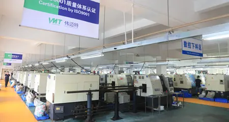
CNC turning establishes straight, stepped, shouldered and threaded cylindrical features in a controlled sequence, making it the primary process for many custom aluminum dowel and locating pins.
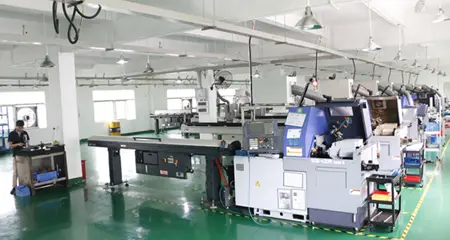
Swiss machining supports suitable small and slender pins close to the cutting zone, helping reduce deflection while combining turning, drilling and selected secondary operations for repeat production.
After the locating diameter is established, CNC milling or drilling adds flats, cross holes, slots and off-axis features while the setup preserves their relationship to the turned datum.
We select aluminum around load, weight, wear, corrosion exposure, finish and the mating component. The alloy should support the finished assembly—not simply be easy to machine.
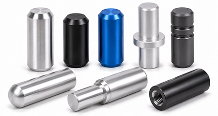
6061-T6 suits lightweight locating and fixture pins; good machinability and corrosion resistance support anodizing, helping balance dimensional control, finish options and production cost.
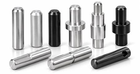
7075-T6 suits higher-load locating pins where weight matters; higher strength supports demanding interfaces, while machining and anodizing are controlled around critical fits.
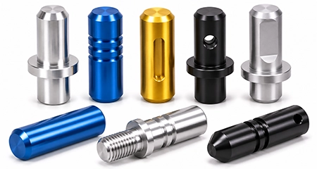
2024 suits selected structural locating pins requiring higher mechanical performance; controlled machining and protective finishing help maintain strength, dimensional stability and reliable assembly.
The best dowel-pin material depends on the mating material, weight target, corrosion exposure, load, wear, installation method, service frequency and whether the locating surface must remain hard through repeated use. We compare these conditions before you lock the material on the drawing.
| Application Requirement / Environment | Aluminum Dowel Pins | Stainless Steel Dowel Pins | Alloy Steel Dowel Pins | What We Recommend You Review |
|---|---|---|---|---|
| Low-weight moving assembly, robotics or portable equipment | Strong choice. 6061 or 7075 can reduce mass while remaining easy to machine into stepped, threaded or custom locating geometry. | Usable, but considerably heavier when mass reduction is a design priority. | Usually selected for strength or wear rather than weight reduction. | Compare required load, pin diameter, engagement length and whether reducing moving mass provides real system value. |
| General industrial locating with moderate load | Often suitable when low weight, corrosion-resistant finishing or non-ferrous construction is important. | Good option when the assembly benefits from higher wear resistance and corrosion resistance without heat treatment. | Suitable when higher strength or future hardening is required. | Review the actual shear load, mating-hole material, fit type and number of assembly cycles before choosing the alloy. |
| Humid, corrosive or wash-down environment | Can work well with a suitable anodized or conversion finish, but damaged coating can expose the base aluminum. | Often the preferred choice where corrosion resistance is required through the bulk material rather than only through a coating. | Usually requires a suitable protective finish unless the selected grade and environment justify another approach. | Define the actual environment, chemical exposure, cleaning process and whether coating damage during service is acceptable. |
| High wear, repeated insertion or sliding contact | Application-dependent. Hard anodizing can improve surface wear, but the softer substrate and coating condition still need review. | Often better for repeated service because many stainless grades provide higher wear resistance than untreated aluminum. | Strong choice when a hardened or highly wear-resistant locating surface is required. | Review mating hardness, contact pressure, sliding distance, insertion cycles and whether the pin is intended to be replaceable. |
| Repeated press fitting, removal and maintenance | Possible for suitable low-load designs, but repeated interference cycles can wear or damage a softer locating surface. | Often more suitable when the pin must survive repeated removal and reinstallation without relying on a surface coating. | Often preferred for severe press-fit service, especially when heat treatment or hardened surfaces are part of the design. | Confirm which side retains the pin, expected service cycles, interference amount, extraction method and mating-hole material. |
| High shear load or heavily loaded locating joint | 7075 may support higher loads than 6061, but the complete joint still needs engineering review. | Provides higher strength options than common aluminum grades while retaining corrosion resistance in suitable grades. | Often the best starting point for severe load, shock or hardened locating applications. | Do not choose from material strength alone; review shear plane, pin diameter, engagement length, support condition and safety factor. |
| Pin running against a hardened steel mating surface | Higher risk of preferential wear on the aluminum pin, especially with repeated movement or removal. | Can provide a more balanced wear relationship depending on the stainless grade and mating hardness. | Can be matched to hardened mating components where wear life is the priority. | Compare hardness mismatch, lubrication, movement and whether controlled pin wear is acceptable as a replaceable element. |
| Pin installed into an aluminum housing or soft mating bore | Can reduce hardness mismatch, but press-fit interference and repeated service still need careful control. | The harder pin can provide durable location, but excessive interference may damage or expand the softer aluminum bore. | Provides a hard locating surface, but the mating aluminum hole becomes the weaker part of the fit system. | Review pin hardness together with bore wall thickness, interference, installation force and whether the housing must be serviceable. |
| Anodized color, lightweight appearance or visible custom finish | Strong choice. Aluminum supports Type II or Type III anodizing and can combine functional machining with branded appearance. | Does not use anodizing; brushed, polished, passivated or suitable PVD finishes may be used instead. | Usually selected for function rather than lightweight anodized appearance; black oxide, plating or other protective finishes may apply. | Separate cosmetic requirements from critical locating surfaces so finishing does not unintentionally change the fit. |
| Close locating fit after surface finishing | Finish buildup can change OD; machining allowance, masking or post-finish verification may be required. | Passivation changes size very little, while plating or PVD must still be considered if applied to the locating diameter. | Plating, black oxide, heat treatment or grinding sequence can affect the final dimensional plan depending on the process. | Define whether the drawing tolerance applies before or after finishing and which surfaces are allowed to receive coating. |
| Hardened, precision-ground locating pin requirement | Not the typical material route for a hardened locating surface. | Possible with suitable grades and process routes, but material and hardness requirements must be confirmed. | Common choice when heat treatment plus precision grinding is needed for high wear and stable locating performance. | If hardness and ground diameter are the primary requirements, consider whether a steel pin is more appropriate than forcing an aluminum solution. |
| Prototype now, repeat production later | Good machinability can make aluminum attractive for rapid design validation, especially when weight and finishing are already part of the final product. | Useful when the prototype must validate the same corrosion and wear behavior expected in production. | May require additional heat-treatment or finishing steps, so the prototype route should reflect the intended production process. | Prototype with the material and finish that affect fit, wear and assembly whenever those properties are part of the validation goal. |
We review finishing as part of the dimensional plan. Coating buildup, masking and stock removal are considered around functional locating surfaces before the process is released.
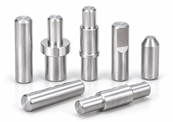
As-machined pins avoid coating buildup on precision locating surfaces, supporting applications where dimensional fit is more important than additional corrosion or wear protection.
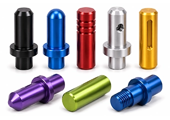
Type II anodizing adds corrosion protection and color; machining allowance or masking protects drawing-controlled diameters so appearance does not compromise assembly fit.
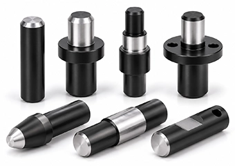
Hard anodizing adds a thicker, harder oxide layer for suitable wear-sensitive pins; coating buildup is planned around locating surfaces to preserve the approved finished diameter.
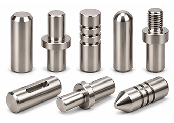
Electroless nickel provides uniform corrosion and wear protection on suitable aluminum pins; plating thickness is included around functional diameters, shoulders and threads before final inspection.
For suitable critical dimensions, our CNC machining capability can reach ±0.005 mm after engineering review. We verify drawing-defined features through first-article, in-process and final inspection using measurement methods matched to the feature geometry.
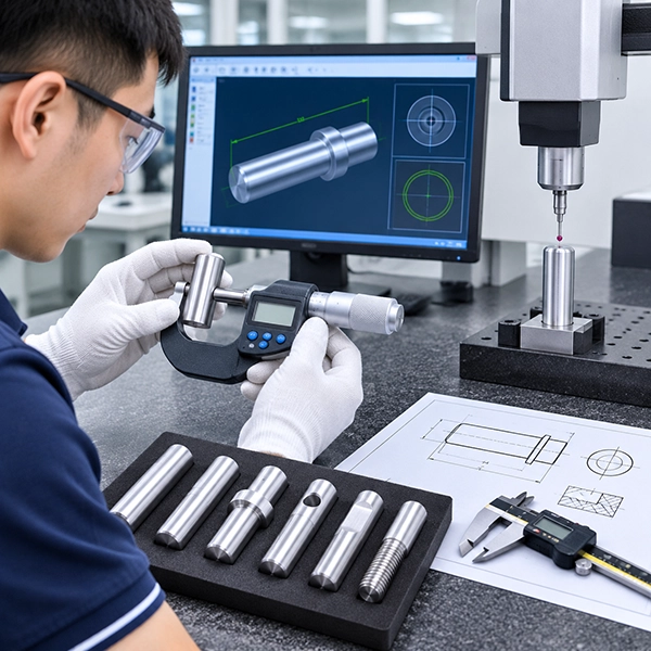
| Feature | Manufacturing Risk | How We Inspect It | Result |
|---|---|---|---|
| Locating OD | Diameter drift creates tight or loose fit. | Micrometer, suitable gauge or drawing-approved measurement; finished OD is rechecked when coating affects size. | Functional locating diameter is verified. |
| Step / Shoulder Position | Incorrect axial location changes seating depth. | Height measurement, 2.5D or CMM according to geometry and drawing requirements. | The pin seats at the intended axial position. |
| Roundness / Straightness | A part can meet OD size but still bind or locate inconsistently. | Appropriate geometry measurement is used when the drawing specifies these requirements. | Cylindrical form is checked separately from size where required. |
| Threads | Threads can tighten after finishing or fail removal / retention. | Suitable go/no-go gauges are used after applicable finishing. | Thread function is verified for assembly. |
| Flat / Cross-Hole Position | Secondary features can shift relative to the locating OD. | 2.5D, CMM or suitable positional inspection is selected according to geometry. | Orientation remains related to the turned datum. |
| Coating / Finished OD | Finishing changes the functional size. | Film-thickness measurement where required plus post-finish dimensional verification. | The customer receives the dimension used in final assembly. |
We machine drawing-specific locating pins for assemblies where fit, repeatability, weight or service access make a standard catalog pin unsuitable.
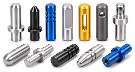
Custom locating pins position workpieces, nests, inspection fixtures and removable tooling where repeated setup accuracy and predictable assembly are required.
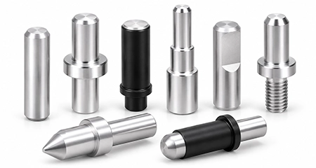
Lightweight locating pins support robot joints, actuator assemblies and removable interfaces where component position and mass reduction must be balanced.
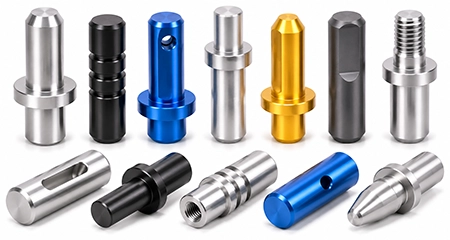
Stepped and shouldered pins locate plates, covers and modular mechanisms where repeatable reassembly depends on stable datum relationships.
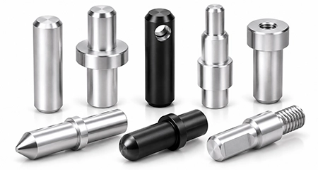
Aluminum locating pins support lightweight housings, instruments and mechanical subassemblies where alignment, corrosion protection and compact geometry matter.
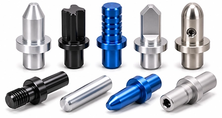
Drawing-specific pins support fixtures, test equipment and selected mechanical assemblies where repeatable position must remain stable through production.
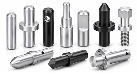
When your mating interface is non-standard, we machine the pin around the actual assembly, fit and service requirement rather than a catalog dimension.
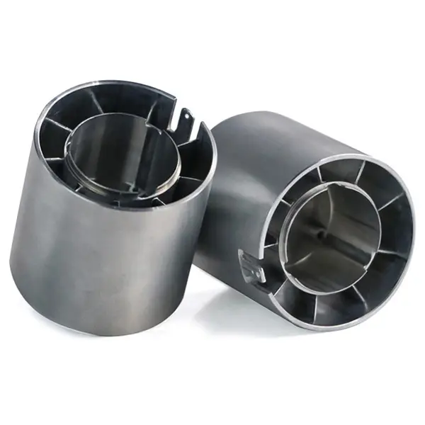
The 6061 aluminum motor housing required micron-level dimensional control, concentric rotating features and a 1 mm thin-wall structure. We used die casting plus CNC machining and process testing to stabilize the part for a 60,000-piece production project.
Customers judge our work after they receive, inspect, assemble and test the parts. The feedback below reflects the results we work to deliver on every CNC project: approved samples, parts that meet expectations and enough confidence to move into the next production order.
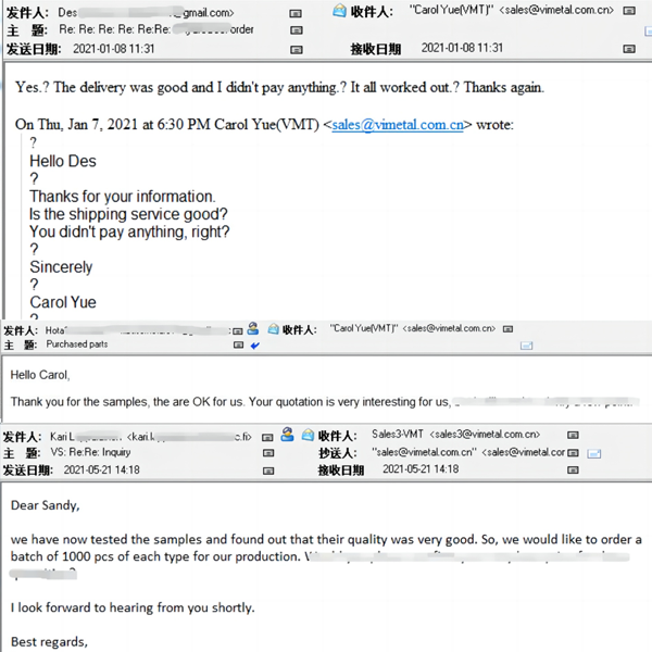
“Yes! All is good. Thanks for doing a great job!”
“We have now tested the samples and found out that their quality was very good.”
“Your parts were perfect, thank-you. I want to order a production quantity soon.”
“Products received! Thanks Wendy and the VMT team. We are really happy with the end product.”
These answers start with what we can support, then explain where material, fit or process choices may change the best manufacturing route.
A: Yes. For suitable pin geometry and critical dimensions, our CNC machining capability can reach tolerances as tight as ±0.005 mm after engineering review. We review diameter, length-to-diameter ratio, alloy and finish before confirming the target, then verify agreed critical dimensions through first-article, in-process and final inspection.
A: Yes. We use CNC turning or Swiss machining for cylindrical features and secondary milling or drilling for flats, slots or cross holes. We establish the locating diameter as the machining reference and inspect secondary-feature relationships according to your drawing.
A: Yes, when the finished dimension is planned before machining. We can review machining allowance, masking and post-anodizing inspection around locating diameters, shoulders and threads that must remain functional after finishing.
A: Yes for many lightweight, corrosion-resistant or non-ferrous assemblies, but not for every duty cycle. For high wear, repeated press fitting or heavy shear loads, we can also compare stainless or alloy steel before quotation so you can select the material around the mating surface, load and service life.
A: Yes. We use prototype and first-article results to confirm the machining route, critical dimensions, finishing requirements and inspection method before repeat production. Agreed critical features can receive in-process or 100% inspection according to the inspection plan.
A: Yes. We can combine dimensional inspection with go/no-go thread gauges, film-thickness measurement and 2D/CMM inspection where required. The inspection method is matched to the feature instead of relying on one measurement tool for every requirement.
Use this guide to review fit, material, machining, finishing and production decisions before releasing a custom dowel-pin drawing.
Start with the function that the pin performs in your assembly. Identify the locating diameter, mating hole, insertion depth, shoulder position, removal requirement and any secondary features such as threads, grooves, flats or cross holes.
Keep tight tolerances on the features that actually control location or assembly. Non-functional surfaces can often use more practical tolerances, reducing machining and inspection cost without weakening the locating function.
A press fit retains the pin through interference, while a slip or locating clearance allows assembly and removal. The correct relationship depends on which component should retain the pin and which component should remain removable.
We review the pin tolerance, mating-hole tolerance and finished surface condition together. For two-pin assemblies, the center distance and secondary locating strategy also matter because two fully constrained round pins can create binding when positional tolerances stack.
6061-T6 is often the practical starting point because it combines machinability, corrosion resistance and anodizing compatibility. 7075-T6 provides higher strength when the pin carries more load while weight must remain low.
Do not select the stronger alloy from strength alone. Engagement length, wear, interference, mating material, finish and service cycle still control whether the complete locating system performs as intended.
Aluminum is attractive when low weight, non-ferrous construction and anodized finishing matter. Stainless steel is often better where corrosion resistance, wear resistance and repeated service are more important.
Alloy steel becomes a stronger candidate for severe loading, hardened locating surfaces or repeated press-fit duty. We can review the mating material and service environment before you finalize the pin material.
Anodizing is not dimensionally invisible. The oxide layer changes the finished diameter, so a locating surface can pass machining inspection and still become too tight after finishing if the coating is not considered beforehand.
We review whether the critical dimension applies before or after finishing and then use allowance, masking or post-finish verification where required.
Conventional CNC turning is efficient for many short straight, stepped, shouldered and threaded pins. Swiss machining becomes useful for smaller or more slender geometry because the stock is supported close to the cutting zone.
We compare the length-to-diameter ratio, secondary features, quantity and repeat-production requirements before choosing the machining route.
Each added feature should solve an assembly problem. A step can separate installation and locating diameters, a shoulder can establish axial position, a thread can support removal and a vent flat or groove can support blind-hole installation.
We review these features around usable locating length, tool access, edge condition, datum relationships and inspection so the extra geometry does not interfere with the pin's primary function.
Keep tight tolerances on the functional locating features and use practical requirements elsewhere. Avoid unnecessary finishing, unusual tool access or extra setups when they do not improve the assembly.
After prototype or first-article approval, lock the machining route, datum strategy, finish condition and inspection method. Repeat production can then use in-process inspection and 100% checks on agreed critical characteristics where the control plan requires it.
Send your 2D drawing, 3D model or available dimensions. We can review the pin-to-hole fit, aluminum grade, machining route, finish and inspection requirements before quotation and production.
 Related suggestion
Give us a call or send an inquiry to our emailbox, we will answer your doubts according to your customers' requirements, and quote you immediately.


 +86 15099911516