16 years one-stop China custom CNC machining parts factory

Hey there I’m VMT Sam!
With 25 years of CNC machining experience we are committed to helping clients overcome 10000 complex part-processing challenges all to contribute to a better life through intelligent manufacturing. Contact us now
 1266 |
Published by VMT at Sep 17 2026 | Reading Time:About 6 minutes
1266 |
Published by VMT at Sep 17 2026 | Reading Time:About 6 minutes


Aluminum parts may look accurate while clamped on a CNC machine, but bend, twist, lose flatness, or move out of tolerance after the fixture is released. For thin walls, large plates, deep pockets, and high material-removal parts, this can cause assembly failure, rework, scrap, and unstable batch production.
Aluminum machining deformation is mainly caused by residual material stress, uneven material removal, clamping force, cutting force, and machining heat. The most effective solution is to identify the actual root cause first, then control the material condition, machining sequence, fixture, toolpath, cutting parameters, and final inspection accordingly.
If your aluminum part is already warping or you are worried about deformation before production, the following guide helps you identify where the problem comes from and which machining controls are most effective.
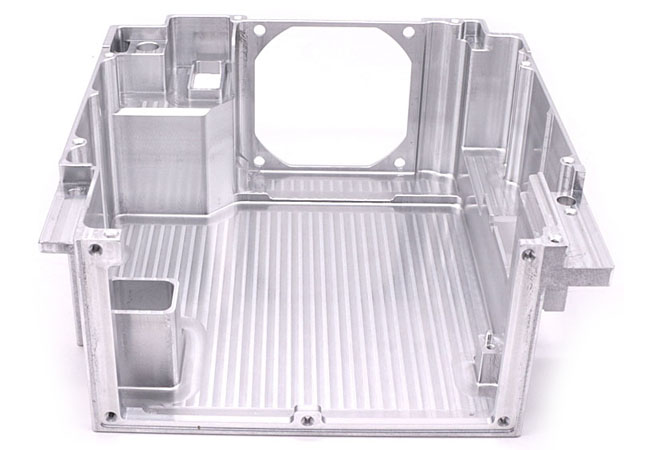
Aluminum is generally easier to machine than stainless steel, titanium, and many high-temperature alloys. However, easy cutting does not automatically mean good dimensional stability.
A CNC machined aluminum part can deform because the original raw material already contains internal stress. Once large amounts of material are removed, the balance of those stresses changes.
New deformation can also be introduced during machining.
The most common causes include:
For this reason, deformation should not be treated as one single machining problem.
The first step is to identify when, where, and how your part changes shape.
The deformation pattern itself often provides useful clues.
| What You See on the Part | Likely Root Cause | What Should Be Checked | Typical CNC Control |
| Plate bends immediately after unclamping | Residual stress or clamping stress | Stock condition, jaw pressure, machining balance | Balanced roughing, stabilization, lower clamping force |
| One side curves after heavy machining | Uneven stress release | Material removed from each side | Symmetrical machining |
| Thin wall springs outward after fixture release | Excessive clamping force | Support position and clamping pressure | Soft jaws, axial support, reduced finishing pressure |
| Dimensions drift while machining | Cutting heat | Part temperature, coolant, tool condition | Heat control and stable cutting parameters |
| Thin wall vibrates or deflects during finishing | Cutting force | Tool engagement and remaining wall stiffness | Lighter finishing cuts and better support |
| Deep-pocket bottom becomes distorted | Low remaining rigidity | Floor thickness and machining sequence | Layered roughing and controlled finishing allowance |
| Bore becomes oval after CNC turning | Chuck or radial clamping force | Jaw pressure and wall thickness | Collet, mandrel, soft jaw or axial clamping |
| Flatness changes after several hours | Residual-stress redistribution | Stock stress and machining sequence | Staged roughing, stabilization and re-finishing |
| Prototype is acceptable but production batches vary | Process inconsistency | Material lot, fixture, tool life, inspection | Standardized process and in-process inspection |
Tip: Do not immediately reduce every feed rate or depth of cut when deformation appears. Lower cutting loads may help, but they will not solve deformation caused primarily by material stress or fixture pressure.
Some aluminum components are naturally more sensitive to dimensional movement than others.
Thin-Wall Aluminum Housings
Thin walls have low stiffness and can move under both cutting and clamping forces. A housing may measure correctly while held in the fixture but spring back after unclamping.
Large Aluminum Plates
Large plates are particularly sensitive to residual stress and unbalanced material removal. Flatness may change substantially if one surface is heavily machined before the opposite side.
Deep-Pocket Components
Removing a large percentage of the original material changes the stiffness and stress balance of the blank. Deep cavities also leave floors and walls that are much more flexible than the original stock.
High Material-Removal Frames
Frames, structural brackets, optical bases, and lightweight aerospace-style components may start from a heavy billet and finish with only a small percentage of the original material remaining.
The greater the material-removal ratio, the more important machining sequence becomes.
Long Thin-Wall Turned Parts
Sleeves, rings, bushings, cylindrical housings, and long tubular components can become oval or tapered when radial chuck pressure and cutting force act on thin sections.
Multi-Cavity Plates
If one cavity is fully machined before the next, the stiffness and internal stress of the plate can become increasingly unbalanced.
These parts benefit from a layered and balanced machining sequence.
The alloy designation alone does not tell you everything about dimensional stability.
For deformation-sensitive parts, you should also consider:
For example, 6061 and 7075 are both widely used for CNC machining, but a thick plate, extrusion, and forged blank may behave differently even when the nominal alloy is similar.
Stress-relieved plate conditions such as T651 or T7351, where applicable, can be useful for deformation-sensitive components because residual stress has been reduced through controlled processing after heat treatment.
A simplified comparison is shown below.
| Material / Condition | General Consideration for Deformation-Sensitive Parts |
| 6061-T6 | Good general machinability; stock condition still needs review |
| 6061-T651 | Common choice for precision plate parts where dimensional stability matters |
| 7075-T6 | High strength; machining strategy and residual-stress control remain important |
| 7075-T651 | Useful for high-strength precision plate components |
| 7075-T7351 | Stress-relieved and overaged condition used where dimensional stability and stress-corrosion resistance are important |
| Cast aluminum tooling plate | Often selected for bases, fixtures, and large flat components requiring good dimensional stability |
The best choice still depends on your required strength, corrosion resistance, surface finish, flatness, wall thickness, and cost.
Note: Selecting a more stable material condition can reduce machining risk, but it cannot compensate for an unbalanced machining sequence or poor fixture design.
Residual stress is one of the most common reasons why a part changes shape after CNC machining.
Before machining, internal tensile and compressive stresses may already be balanced inside the raw stock.
When you remove material from one region, that equilibrium changes.
The remaining material then redistributes the stress and the part may:
This explains why a part can be perfectly stable while most of the stock is still present but begin to move after deep pocketing or aggressive weight reduction.
How Can Residual-Stress Deformation Be Reduced?
A more stable process often uses multiple machining stages rather than attempting to finish the part directly from the raw blank.
A typical sequence may be:
During roughing, enough material should remain around critical surfaces to allow later correction.
The correct finishing allowance depends on:
There is no single roughing or finishing allowance that should be applied to every aluminum part.
Machining too much material from one area or one side of a workpiece can release stress unevenly.
This is especially important for:
Use Symmetrical Machining Where Possible
Suppose both sides of an aluminum plate need substantial material removal.
A high-risk process would be:
By the time Side B is machined, Side A may already have released stress and changed shape.
A more balanced strategy may be:
This keeps the remaining section thickness and residual-stress release more balanced.
Symmetrical machining does not mean every feature must be geometrically identical. It means the machining plan should avoid unnecessarily concentrating material removal on one region while the rest of the workpiece remains highly rigid.
For aluminum plates containing several deep pockets, machining one cavity completely before starting the next may create uneven stiffness.
A more stable method is often layered machining.
Instead of:
Cavity 1 to full depth → Cavity 2 to full depth → Cavity 3 to full depth
the process may follow:
Machine a controlled depth in all cavities → repeat another layer → continue progressively toward final depth.
This approach can help distribute:
Toolpath design should also avoid sudden full-width engagement or large changes in cutter load when machining weak walls and thin floors.
Example: Reduce the Internal Stress of the Blank
Natural or artificial aging and vibration treatment can partially eliminate the internal stress of the blank. Pre-processing is also an effective process method. For larger blanks, due to the large allowance, the deformation after processing is also large. If the excess parts of the blank are machined in advance and the allowance of each part is reduced, it can not only reduce the deformation of the CNC machining in the subsequent process, but also release a part of the internal stress after being placed for a period of time after the CNC machining in advance.
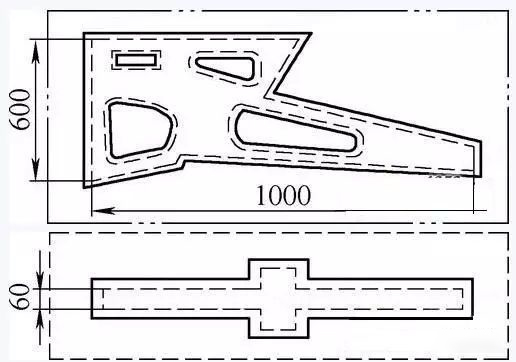
For example, Figure 1 shows a beam part, the shape of the blank as shown by the double-dotted line in the figure weighs 60kg, while the part weighs only 3kg. If it is processed and formed at one time according to the dotted line in the figure, the flatness error can be as high as 14mm. If the pre-processing is carried out according to the solid line in the figure, and then processed into the required aluminum parts after natural aging for a period of time, the flatness error can be reduced. as small as 3mm.
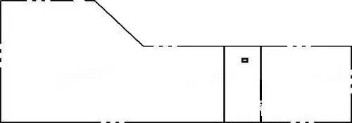
Figure 2 shows a part of a certain type of cap piercer, the local minimum thickness is only 3mm, and the thickness of the blank before CNC machining is 20mm. The aluminum parts can be directly processed to the size by changing the pressure plate on the CNC machining center, but when they are removed from the worktable, the bottom ends of the aluminum parts will be lifted up, resulting in serious oversize or even scrapped.
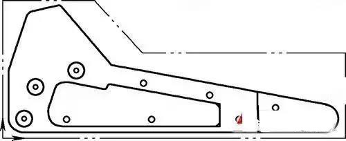
Therefore, before CNC machining, a stress relief groove is first opened on the blank, as shown by the solid line in Figure 3, and then removed from the worktable, and the natural aging is 1 to 2 hours, so that the deformation occurs as much as possible at this time. After that, a fitter leveling process is added to level the part, and the deformation of the part in the subsequent processing will be greatly reduced.
One of the most common reasons a thin aluminum part looks accurate during machining but changes after unclamping is fixture-induced deformation.
The fixture may be forcing the part into a temporary shape.
The CNC machine then cuts that distorted shape accurately.
When the clamping force is released, the component elastically returns toward its natural condition, and the dimensions change.
How Can Fixture-Induced Deformation Be Reduced?
Depending on the part geometry, useful workholding methods include:
The correct goal is not:
Clamp the part as tightly as possible.
It is:
Use enough holding force to resist cutting loads while introducing as little distortion as possible.
For thin-wall parts, fixture force should be considered together with cutting force.
Reducing one while ignoring the other may not solve the problem.
In many deformation-sensitive applications, yes.
After rough machining, the part may already have changed slightly because stress has been released.
If finishing is performed without allowing the part to settle into its new condition, the final dimensions may still move after removal.
A more stable method can include:
This approach is especially useful for thin walls, large plates, deep-pocket housings, and high material-removal components.
Improve the Tool Structure
1、Reduce the number of teeth of the milling cutter and increase the chip space. Due to the large plasticity of the aluminum material and the large cutting deformation during processing, a large chip space is required, so the bottom radius of the chip groove should be large and the number of milling cutter teeth should be small.
2、Finely grind the teeth. The roughness value of the cutting edge of the cutter teeth should be less than Ra=0.4um. Before using a new knife, you should use a fine oil stone to lightly sharpen the front and back of the knife teeth a few times to eliminate the burrs and slight serrations left when sharpening the teeth. In this way, not only can the cutting heat be reduced, but also the cutting deformation is relatively small.
3、Strictly control the wear standard of the tool. After the tool is worn, the surface roughness value of the workpiece increases, the cutting temperature rises, and the workpiece deformation increases. Therefore, in addition to the selection of tool materials with good wear resistance, the tool wear standard should not be greater than 0.2mm, otherwise it is easy to produce built-up edge. When cutting, the temperature of the workpiece should generally not exceed 100 ℃ to prevent deformation.
Even when the raw material and fixture are stable, cutting force can temporarily bend weak features.
For thick stock, this deflection may be negligible.
For thin walls or floors, the cutter can push the material away from its nominal position.
The tool then removes less material than expected.
When the cutter passes, the wall springs back, causing dimensional error.
How Can Cutting Force Be Reduced?
For aluminum, the machining process should generally focus on:
The goal is not simply to use the lowest feed or depth of cut.
An extremely light cut with a worn or rubbing cutter can also generate unnecessary heat and unstable surface quality.
Aluminum has relatively high thermal conductivity, but it also expands as temperature changes.
If a precision aluminum component becomes significantly warmer during machining, dimensions measured immediately on the machine may differ from those measured after the part returns to a stable inspection temperature.
Heat can come from:
For tight-tolerance components, the supplier should control both machining heat and inspection conditions.
How Can Machining Heat Be Controlled?
Depending on the operation, this may involve:
Instead of applying one universal maximum workpiece temperature, temperature control should be based on part size, alloy, tolerance, cycle time, and inspection requirement.
Example: Improve the Cutting Ability of the Tool
The material and geometric parameters of the tool have an important influence on the cutting force and cutting heat. The correct selection of the tool is very important to reduce the deformation of aluminum parts.
Reasonable Selection of Tool Geometric Parameters
Improve the Tool Structure
Reasonable Arrangement of Processes
During high-speed cutting, due to the large CNC machining allowance and intermittent cutting, the milling process often generates vibration, which affects the CNC machining accuracy and surface roughness. Therefore, the CNC high-speed cutting process can generally be divided into: roughing-semi-finishing-corner-clearing-finishing and other processes. For the processing of aluminum parts with high precision requirements, it is sometimes necessary to perform secondary semi-finishing and then finishing. After rough machining, aluminum parts can be cooled naturally, eliminating the internal stress caused by rough machining and reducing deformation. The allowance left after rough machining should be greater than the deformation, generally 1 to 2 mm. When finishing, the finishing surface of the parts should maintain a uniform machining allowance, generally 0.2 ~ 0.5mm, so that the tool is in a stable state during the CNC machining process, which can greatly reduce cutting deformation and obtain good surface CNC machining quality , to ensure the accuracy of Aluminum parts machining.
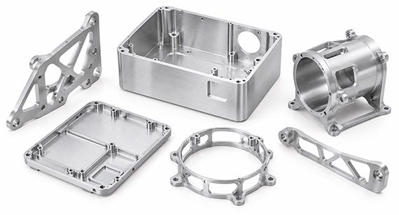
Thin-wall aluminum components combine several deformation risks at the same time:
For these parts, deformation control should begin during DFM review.
1. Keep Temporary Support Where Possible
If the design allows, some material can remain temporarily during roughing to support weak walls.
The support is removed only during later finishing operations.
2. Machine Strong Features Before Weak Features
Removing supporting material too early can leave thin walls exposed to cutting loads for the rest of the process.
Machining sequence should preserve stiffness as long as practical.
3. Use Stable Wall-Finishing Toolpaths
Alternating wall passes, controlled radial engagement, or progressive depth strategies may reduce wall deflection compared with aggressive full-depth side cutting.
4. Reduce Finish Clamping Pressure
The part may require more holding force during roughing than during the final dimensional pass.
Where the fixture design allows, finish machining under reduced and more evenly distributed force can improve free-state accuracy.
5. Inspect the Part After Unclamping
A thin wall that measures correctly while constrained may still be incorrect in its natural state.
Final inspection should reflect the condition required in your assembly.
Large aluminum plate deformation is a common concern for machine bases, mounting plates, automation fixtures, optical bases, electronics structures, and precision frames.
The most important controls usually include:
Select Suitable Plate Stock
Material condition matters more as plate size and material-removal ratio increase.
Avoid One-Sided Heavy Roughing
Remove material progressively from both sides where the design and fixture permit.
Leave Finishing Allowance
Do not create final flatness before the majority of residual stress has been released.
Re-Establish the Datum
After roughing and stabilization, re-reference the part instead of assuming the original roughing datum remains ideal.
Support the Plate Correctly
A plate should not be pulled flat against a fixture and then machined as though that forced condition represents the final free state.
Verify Flatness After Release
Flatness should be checked under the condition specified by the drawing and application.
Tip: If flatness is critical to your assembly, clearly specify the flatness tolerance, datum, measurement condition, and functional surface on your drawing.
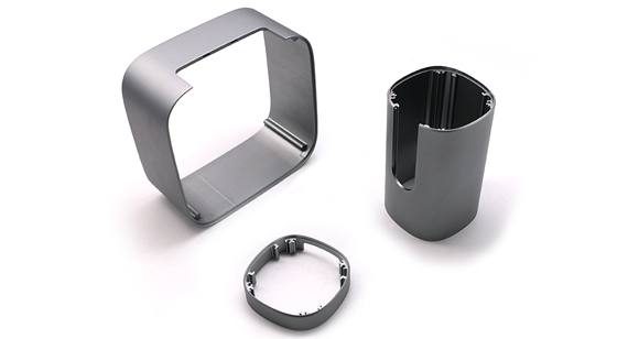
CNC turning introduces a different set of deformation problems from milling.
Thin-wall sleeves, bushings, rings, and cylindrical housings are especially sensitive to radial chuck pressure.
If the jaws squeeze a thin cylindrical part, the component may become slightly oval while it is clamped.
The CNC machine then turns a round diameter relative to the distorted condition.
When the jaws open, the part springs back and the bore or outside diameter may no longer be round.
Depending on your part, VMT may consider:
Long, thin components also require attention to support, tool pressure, runout, concentricity, and vibration.
No single milling direction solves every deformation problem.
On modern rigid CNC machines, climb milling is commonly used for many aluminum finishing operations because it can reduce rubbing and provide good surface quality under suitable conditions.
However, deformation depends on the entire system:
The machining strategy should therefore be selected around the part, not around one universal rule.
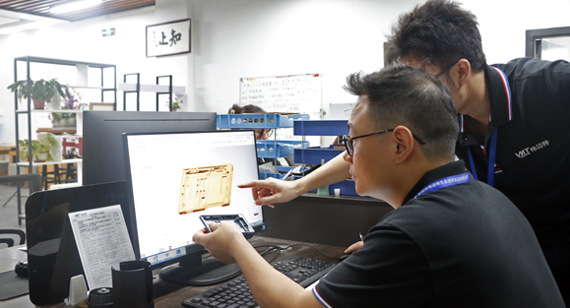
Many deformation problems can be predicted from a 2D drawing and 3D model before machining begins.
During DFM review, VMT engineers can evaluate:
Sometimes a small design change can reduce risk more effectively than slowing down the entire machining process.
For example, adding temporary stock, changing a machining datum, slightly increasing a non-functional wall, or modifying an internal corner may improve rigidity and reduce both machining time and deformation risk.
In addition to improving the performance of the tool and eliminating the internal stress of the material by aging treatment in advance, in actual operation, the use of appropriate operating methods can effectively avoid the deformation of the material during CNC machining.
1. Symmetrical Processing Method
For aluminum parts with large CNC machining allowance, in order to make them have better heat dissipation conditions during the CNC machining process and avoid heat concentration, symmetrical machining should be adopted during CNC machining. If a 90mm thick sheet needs to be processed to 60mm, if one side is milled and the other side is milled immediately, and the final size is processed at one time, the flatness will reach 5mm; if it is processed symmetrically with repeated feeding, each side is processed twice to The final dimension can guarantee a flatness of 0.3mm.
2. Layered Multiple Processing Method
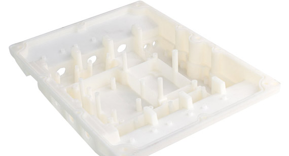
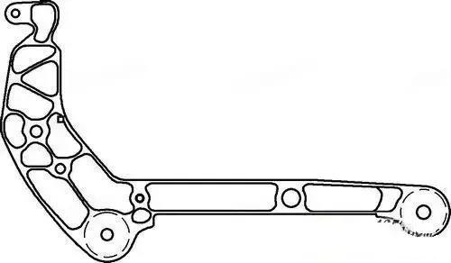
If there are multiple cavities on the sheet part, as shown in the picture below. During CNC machining, it is not appropriate to use the sequential CNC machining method of one cavity and one cavity, which will easily cause uneven processing of aluminum parts and cause deformation. Multi-layer processing is adopted, and each layer is processed to all the cavities at the same time as possible, and then the next layer is processed to make the aluminum parts process evenly stressed and reduce deformation.
3. Proper Selection of Cutting Amount
The cutting force and cutting heat can be reduced by changing the cutting amount. Among the three elements of cutting amount, the amount of back-engagement has a great influence on the cutting force. If the CNC machining allowance is too large, the cutting force of one pass is too large, which will not only deform the aluminum parts, but also affect the rigidity of the machine tool spindle and reduce the durability of the tool. If the amount of knives to be eaten by the back is reduced, the production efficiency will be greatly reduced. However, high-speed milling is used in CNC machining, which can overcome this problem. While reducing the amount of back-engagement, as long as the feed is increased accordingly and the speed of the machine tool is increased, the cutting force can be reduced and the processing efficiency of aluminum parts can be guaranteed at the same time.
4. Pay Attention to the Order of the Knives
Roughing and finishing should use different pass sequences. Rough machining emphasizes improving the processing efficiency of aluminum parts and pursuing the removal rate per unit time. Generally, up-cut milling can be used. That is, the excess material on the surface of the blank is removed at the fastest speed and the shortest time, and the geometric contour required for finishing is basically formed. While finishing emphasizes high precision and high quality, it is advisable to use down milling. Because the cutting thickness of the cutter teeth gradually decreases from the maximum to zero during down milling, the degree of CNC machining hardening is greatly reduced, and the deformation degree of Aluminum parts machining is also reduced.
5. Secondary Compression of Thin-Walled Parts
Thin-walled workpieces are deformed due to clamping during CNC machining, and even finishing is unavoidable. In order to reduce the deformation of the workpiece to a minimum, you can loosen the pressing part before finishing the final size, so that the workpiece can freely return to its original state, and then slightly press it, as long as the workpiece can just be clamped, so that The ideal CNC machining effect can be obtained. In short, the action point of the clamping force is preferably on the supporting surface, and the clamping force should act in the direction of the rigidity of the aluminum parts. On the premise of ensuring that the aluminum parts are not loosened, the smaller the clamping force, the better.
6. Drilling Before Milling
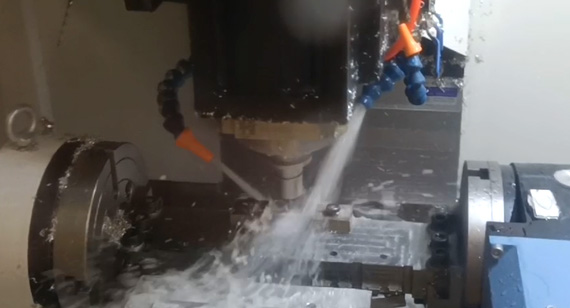
When CNC machining aluminum parts with a cavity, try not to let the milling cutter plunge directly into the part like a drill when machining the cavity, resulting in insufficient space for the milling cutter to hold the chips, and the chip removal is not smooth, resulting in overheating and expansion of the aluminum parts. And the unfavorable phenomena such as broken knife and broken knife. First drill the hole with a drill of the same size as the milling cutter or one size larger, and then mill it with the milling cutter. Alternatively, CAM software can be used to produce helical rundown programs.
At VMT, deformation control starts before production, not after a failed final inspection.
For deformation-sensitive aluminum components, the process can include:
1. Engineering and DFM Review
Your 2D drawing and 3D model are reviewed for thin walls, deep cavities, flatness, material-removal ratio, tolerance stacking, fixture access, and inspection risk.
2. Material Review
The alloy, temper, stock form, material certificate requirements, and dimensional-stability risks are evaluated according to your application.
3. Fixture Optimization
Soft jaws, custom fixtures, vacuum holding, axial support, mandrels, and other workholding strategies are selected according to part geometry.
4. Machining Sequence Control
Large material-removal parts can be divided into roughing, stabilization, semi-finishing, and finishing stages.
5. Toolpath and Cutting Control
Cutting engagement, tool selection, wall-finishing strategy, chip evacuation, and machining heat are managed according to feature rigidity.
6. In-Process Inspection
Critical dimensions can be checked before all finishing operations are complete so that process drift is detected earlier.
7. Final Dimensional Inspection
Depending on your drawing, inspection may include CMM measurement, flatness, parallelism, perpendicularity, hole position, bore diameter, concentricity, profile, or assembly-related dimensions.
For precision projects, VMT supports engineering review, prototype validation, CNC milling, CNC turning, 5-axis machining, in-process inspection, CMM inspection, and production quality control.
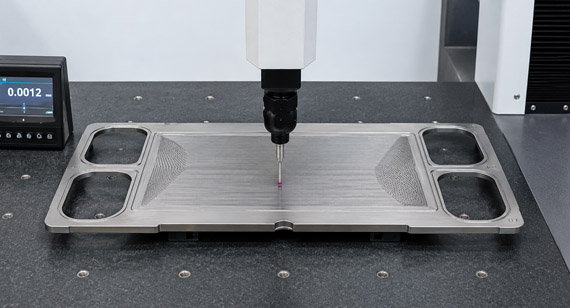
Machining is only one part of deformation control.
The inspection method must also match the functional requirement.
For deformation-sensitive components, important characteristics can include:
Inspect the Free-State Condition When Required
If a customer uses a component without external restraint, inspection should not hide deformation by forcing the part flat.
Allow Thermal Stabilization
For tight-tolerance aluminum components, final dimensions should be verified under suitable temperature conditions.
Use the Correct Datum System
A flatness or hole-position measurement is only meaningful when the part is referenced according to the drawing and assembly function.
Monitor Production Batches
For repeated production, first-article inspection and in-process checks can identify dimensional drift before an entire batch is completed.
The following example illustrates the process logic rather than representing a specific customer performance claim.
Project Background
A machined aluminum housing contains a large internal cavity, several precision mounting holes, and relatively thin side walls.
The assembly requires stable hole position and flatness after the part is removed from the fixture.
Problem
If the internal cavity is machined aggressively in one operation, a large percentage of the original billet is removed while the part remains highly constrained by the fixture.
After unclamping, the housing may:
Root Cause
The likely causes are a combination of:
Machining Solution
A more stable process can use:
Validation
Flatness, hole position, wall dimensions, and assembly surfaces should then be verified after the part reaches a stable inspection condition.
This validation step determines whether the process is actually controlling deformation rather than merely producing a temporary in-fixture result.
A prototype that meets tolerance once does not automatically mean the process is ready for volume production.
Batch stability depends on controlling variables such as:
For deformation-sensitive parts, the prototype stage should be used to validate not only the final dimensions but also the manufacturing route.
Once the process is confirmed, key parameters and inspection points can be standardized for repeat production.
This is especially important for parts where distortion affects:
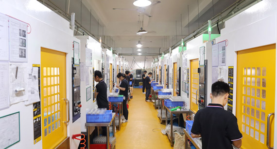
If your aluminum part includes thin walls, large plates, deep cavities, high material removal, tight flatness, precision holes, or difficult assembly tolerances, deformation should be reviewed before machining starts.
Send VMT your 2D drawings and 3D models. Our engineering team can review your material, wall thickness, machining sequence, fixture strategy, tolerance risks, surface finishing, and inspection requirements, then provide DFM feedback before prototype or batch production.
For projects requiring precision control, VMT can support CNC milling, CNC turning, 5-axis machining, prototype validation, in-process inspection, CMM inspection, surface finishing coordination, final inspection, and protective packaging from prototype through repeat production.
Send your 2D drawings, 3D CAD models, aluminum grade and temper, wall thickness, critical tolerances, flatness requirements, prototype quantity and production quantity. VMT will review material condition, machining sequence, fixture strategy, deformation risks, inspection and quotation requirements.
All information and uploaded files are secure and confidential.
1 Tell us what you need
2 Get solution & quote
3 Approve production
Email: inquiry@vimetal.com.cn
Why does my aluminum part deform only after it is removed from the CNC fixture?
The fixture may be restraining residual-stress movement or physically distorting the workpiece during machining. When the fixture is released, the part returns toward its natural shape. The solution may involve balanced roughing, lower finishing pressure, stabilization, and re-clamping before final machining.
How can I reduce aluminum plate warping during CNC machining?
Use stable plate material, avoid heavy one-sided material removal, machine opposing surfaces progressively, leave finishing allowance, re-establish the datum after roughing, and verify flatness after the part is released from the fixture.
Is residual stress the main cause of aluminum deformation?
Residual stress is one major cause, especially in large plates and high material-removal parts. However, cutting force, machining heat, fixture pressure, wall stiffness, and process sequence can also create or increase deformation.
Which aluminum alloy is best for dimensional stability?
There is no single alloy that is always best. Alloy, temper, stock form, strength requirement, corrosion resistance, and geometry must be considered together. Stress-relieved plate conditions can be useful for precision plate components.
Does reducing the depth of cut prevent deformation?
Not necessarily. Smaller cuts can reduce cutting force, but they do not solve deformation caused by residual stress, excessive clamping force, or an unbalanced machining sequence.
How do you prevent thin-wall aluminum parts from deforming?
Common methods include preserving temporary support, optimizing machining sequence, using low-distortion fixtures, reducing finish clamping pressure, controlling tool engagement, and checking dimensions after unclamping.
Why does an aluminum bore become oval after CNC turning?
Thin cylindrical components may deform under chuck pressure. When the jaws are released, the part springs back and roundness changes. Soft jaws, collets, mandrels, axial clamping, or reduced pressure can help.
Can deformation be predicted from a CAD model?
Many deformation risks can be identified during DFM review. Thin walls, deep pockets, high material-removal ratios, weak fixture surfaces, and critical flatness requirements can all be evaluated before machining.
Should aluminum parts be inspected immediately after machining?
Not always. For tight-tolerance components, machining heat or residual-stress redistribution may affect the result. Final measurement should be performed under an appropriate stable condition.
How can I make sure deformation does not return during mass production?
The supplier should control material condition, fixtures, machining sequence, tool life, in-process inspection, final inspection, and production documentation rather than relying only on a successful first prototype.


 +86 15099911516




 Read more