15 years one-stop China custom CNC machining parts factory

Hey there I’m VMT Sam!
With 25 years of CNC machining experience we are committed to helping clients overcome 10000 complex part-processing challenges all to contribute to a better life through intelligent manufacturing. Contact us now
 1621 |
Published by VMT at Sep 21 2021
1621 |
Published by VMT at Sep 21 2021


GD&T is the abbreviation of Geometric Dimensioning and Tolerancing (Geometric Dimensioning and Tolerancing) is widely used internationally, and clearly and accurately defines the size, shape, direction, and location of geometric product functions. From the 1940s until today, it has been widely used in many industries such as national defense and military industry, aerospace, automobiles, engineering machinery, electronic appliances, and medical equipment. This article describes the basic knowledge, definitions and GD&T symbol table of GD&T.
CNC machining has revolutionized the manufacturing industry with its ability to produce complex and precise parts with remarkable efficiency. To ensure the accuracy and quality of CNC machined components, the understanding and application of Geometric Dimensioning and Tolerancing (GD&T) play a crucial role. In this article, we will explore the basics of GD&T in the context of CNC machining, providing valuable insights into this important aspect of modern manufacturing.
1. What is CNC Machining?
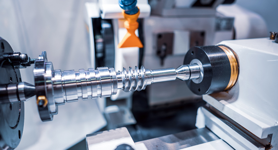
CNC machining, or Computer Numerical Control machining, is a manufacturing process that utilizes computerized systems to control the movement and operation of cutting tools. By following precise instructions programmed into the system, CNC machines can produce intricate parts from a variety of materials such as metal, plastic, or wood.
Definition and Explanation
CNC machining involves the use of computer-aided design (CAD) software to create a virtual model of the desired part. The CAD model is then translated into machine code that guides the CNC machine's movements. The machine code consists of a series of instructions that specify the toolpath, cutting parameters, and other relevant details.
During the machining process, the CNC machine removes material from the workpiece according to the programmed instructions, resulting in a finished part that meets the desired specifications. CNC machining offers unparalleled precision and repeatability, making it an indispensable technique in various industries, including aerospace, automotive, and medical.
Benefits and Applications
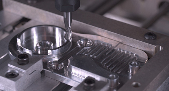
The advantages of CNC machining are numerous. First and foremost, it enables the production of complex geometries that would be challenging or even impossible to achieve manually. CNC machines can execute intricate cutting patterns, create fine details, and achieve high levels of accuracy consistently.
Additionally, CNC machining offers exceptional efficiency and productivity. Once the program is set up, the machine can run autonomously, allowing manufacturers to achieve higher production volumes in less time. Moreover, CNC machines can be easily reprogrammed to produce different parts, making them highly versatile and cost-effective.
The applications of CNC machining are diverse and extensive. It is commonly used in the production of automotive components, aerospace parts, medical devices, consumer electronics, and custom-made products. The ability to precisely control the machining process makes CNC machining suitable for both prototyping and large-scale manufacturing.
What is GD&T?
The tolerance system used to define and communicate engineering design and computer-generated 3D solid models refers to the accuracy and precision requirements of CNC machining parts. GD&T usually refers to the American standard ASME Y14.5, the current 2018 edition.
GD&T, short for Geometric Dimensioning and Tolerancing, is a symbolic language used to define and communicate the allowable variations in the form, orientation, and location of features on a part. It provides a standardized way to specify the dimensions and tolerances of geometric features, ensuring clear and unambiguous communication between designers, manufacturers, and inspectors.
Definition and Explanation
GD&T offers a comprehensive set of rules and symbols that allow engineers and manufacturers to precisely define the desired geometric characteristics of a part. By using GD&T, designers can specify tolerances that govern the acceptable limits of variation for features such as straightness, flatness, circularity, position, and more.
The purpose of GD&T is to ensure that the manufactured parts conform to the design intent, fit together properly, and function as intended. It provides a common language that eliminates ambiguities and reduces the reliance on traditional dimensioning methods, which often lack the necessary level of detail and clarity.
Importance in CNC Machining
In the realm of CNC machining, where precision and accuracy are paramount, GD&T plays a crucial role. By applying GD&T principles, engineers can effectively communicate the design requirements to CNC machine operators, ensuring that the resulting parts meet the desired specifications.
GD&T allows for a more comprehensive and precise definition of part features and their tolerances. It provides a framework for specifying the allowable variation in form, orientation, and location, enabling the machinist to understand the intended design intent and make the necessary adjustments to achieve the desired outcome.
The use of GD&T in CNC machining promotes consistency, reduces errors, and improves the overall quality of the manufactured parts. It facilitates efficient communication throughout the design and manufacturing process, minimizing misunderstandings and ensuring that the end product meets the customer's expectations.
Key Concepts of GD&T
To effectively apply GD&T in CNC machining, it is essential to understand the key concepts and elements of this symbolic language. The following sections will introduce the fundamental aspects of GD&T, including datums, geometric controls, tolerances and symbols, and feature control frames.
Datums
Datums are reference points or surfaces used to establish the coordinate system for dimensional measurements. They provide a basis for defining and interpreting the tolerances and geometric relationships of other features on the part.
In GD&T, datums are represented by capital letters such as A, B, C, etc. They are typically identified on the part using datum targets or specific features that are defined as primary, secondary, or tertiary datums. The proper selection and arrangement of datums are crucial for accurately defining the part's geometry.
Geometric controls in GD&T specify the acceptable variations in the shape, size, and orientation of features on a part. They include parameters such as straightness, flatness, circularity, position, profile, and runout. Each geometric control has its own symbol and set of rules that define its meaning and application.
By using geometric controls, designers can precisely communicate the desired tolerances for features, ensuring that they are within the acceptable limits. Geometric controls provide a more comprehensive and explicit representation of part features compared to traditional linear dimensions.
Tolerances define the allowable variation in dimensions, form, and position of features. They specify the maximum permissible deviation from the ideal or nominal dimensions. In GD&T, tolerances are indicated using various symbols and modifiers that convey specific meanings.
The symbols used in GD&T include basic symbols such as diameter, radius, and perpendicularity, as well as modifiers like maximum material condition (MMC) and least material condition (LMC). These symbols, combined with dimensional values, establish the tolerances and constraints for different features on the part.
Feature Control Frames
Feature control frames are used in GD&T to combine multiple geometric controls and tolerances into a single notation for a feature or a set of features. They provide a compact and organized way to represent the dimensional requirements for complex features.
A feature control frame consists of various components, including the geometric control symbol, tolerance values, datums, and additional modifiers if necessary. It presents a clear and concise representation of the part requirements, facilitating easy interpretation and implementation during CNC machining.

Related standards and specifications of GD&T:
The term GD&T originated from the United States. The ASME Y14 series standards of the American Society of Mechanical Engineers are all related to GD&T. The following are commonly used:
1.ASME.Y14.2—2008 Line Conventions and Lettering
Y14.2 specifies the line type, line width and application used in computer-aided design (CAD) or manual drawing; at the same time, it specifies the font of the drawing and the minimum character height used in different drawing frames. In addition, standards related to drawing engineering drawings include Y14.1, Y14.3, Y14.24, Y14.34, Y14.35, Y14.38, Y14.100, etc.
2.ASME Y14.8—2009 Castings, Forgings and Molded Parts
Generally, the structure of the molded part is more complicated, and the benchmark target is used to establish the benchmark, which is designed and manufactured by the mold. Y14.8 explains the design of molded parts and molds, the selection and application of reference targets for irregular rigid parts, the selection and application of reference targets for flexible (injection) parts, the detection and fixture design of flexible (injection) parts, and GD&T in the design of injection molds. Application and testing methods, etc.
3.ASME Y14.43—2011 Dimensioning and Tolerancing Principles for Gages and Fixtures
Inspection fixture is an important means to realize product inspection, and its structure and tolerance distribution have a vital influence on the judgment of product quality. The correct design of the gage structure and the reasonable allocation of gage tolerances not only help reduce the risk of measurement, but also help reduce costs. Y14.43 provides a design method for functional inspection tools to verify the contour and effective boundary under the maximum physical condition.
At the same time, it provides three principles for the tolerance allocation of inspection tools: absolute tolerance principle (pessimistic principle), optimistic tolerance principle and Tolerance tolerance principle: On the premise of satisfying the functional requirements of the workpiece, a reasonable selection of the tolerance distribution principle can not only reduce the manufacturing cost of the inspection tool, but also appropriately increase the proportion of qualified products.
4.ASME Y14.41—2012 Digital Product Definition Data Practices
Y14.41 defines the basic criteria for the definition of digital products based on 3D, laying a foundation for all-round applications of 3D data throughout design, manufacturing and testing. It is suitable for both 3D product development mode (Model Only) and 3D and 2D. Mixed research and development model (Model and Drawing). In addition to model data and revision history, 3D digital product definition also includes related data such as materials, processes, analysis data, and test requirements. For the 3D R&D mode (Model Only), drawings are no longer needed; the direct application of geometric dimensions and tolerances to 3D digital models is the development trend of GD&T.
5.ASME Y14.36—2018 Surface Texture Symbols
The surface of the part formed by processing is in a non-ideal state, and its characteristics can usually be separated into surface roughness, surface waviness, surface shape error, and surface defect. Y14.36 specifies the methods for controlling the surface texture of solid materials, including methods for controlling roughness, waviness and texture direction, and provides marking symbols used in engineering drawings and related documents; however, it does not specify methods for controlling or measuring waviness.
6.ASME Y14.5—2018 Dimensioning and Tolerancing
Y14.5 is the most important authoritative standard of GD&T. It determines the principles, definitions, requirements, defaults or recommended practices for the geometric dimensions and tolerances and related requirements in engineering drawings and related documents. The content covers basic rules, symbols, and dimensions. Tolerance, datum (system), geometric tolerance (shape, direction, position, profile, runout) and various combinations and applications, etc. Compared with the previous version, the current 2018 version is carried out in the concept of dimensional elements, the expression of the datum reference system and the degree of freedom, the composite position tolerance, the surface interpretation and axis interpretation of the position degree, the contour tolerance, symbols and modifiers, etc. Updated.
Understanding Geometric Controls in GD&T
GD&T encompasses a wide range of geometric controls that define the allowable variations in the form, orientation, and location of features on a part. This section explores some of the commonly used geometric controls in GD&T and their significance in CNC machining.
Straightness, Flatness, and Roundness
Straightness is a geometric control that defines the allowable deviation from a perfect straight line for a feature. It ensures that the specified feature remains within a specified tolerance zone, preventing excessive bending or curving.
Flatness, on the other hand, specifies the acceptable variation in the flatness of a surface. It ensures that the surface remains within a specified tolerance zone, preventing excessive waviness or warping.
Roundness is a geometric control that governs the allowable variation in the roundness or circularity of a feature. It ensures that the feature remains within a specified tolerance zone, preventing excessive out-of-roundness.
These geometric controls are essential in CNC machining to ensure the desired shape and geometry of features. By applying straightness, flatness, and roundness controls, manufacturers can achieve the required level of precision and surface quality in the machined parts.
Circularity, Cylindricity, and Concentricity
Circularity is a geometric control used to specify the allowable variation in the circular shape of a feature, such as a hole or a boss. It ensures that the feature remains within a specified tolerance zone, preventing excessive deviation from a perfect circle.
Cylindricity, on the other hand, governs the allowable variation in the cylindrical shape of a feature, such as a shaft or a bore. It ensures that the feature remains within a specified tolerance zone, preventing excessive deviation from a perfect cylinder.
Concentricity is a geometric control that defines the allowable variation in the alignment of two or more features, such as the center axis of a hole with respect to a datum. It ensures that the features remain within a specified tolerance zone, ensuring proper alignment and concentricity.
These geometric controls are particularly important in CNC machining, where cylindrical features and their alignment play a critical role in various applications. By applying circularity, cylindricity, and concentricity controls, manufacturers can achieve precise and properly aligned features.
Position, Profile, and Runout
Position is a geometric control that specifies the allowable deviation of a feature from its true position with respect to a datum or a reference point. It combines both location and orientation tolerances to define the acceptable variation in the feature's position.
Profile is a geometric control that defines the allowable variation in the shape of a feature, considering all the points along its length or periphery. It ensures that the feature remains within a specified tolerance zone, preventing excessive deviation from the ideal shape.
Runout is a geometric control that governs the allowable variation in the circularity, cylindricity, or profile of a feature as it rotates. It ensures that the feature remains within a specified tolerance zone, preventing excessive wobbling or eccentricity.
Position, profile, and runout controls are essential in CNC machining to ensure the accurate positioning, shape, and alignment of features. By applying these geometric controls, manufacturers can achieve the desired dimensional accuracy and functionality of the machined parts.
GD&T Symbols and Tolerances
GD&T utilizes a set of symbols and modifiers to represent the various geometric controls and tolerances. Understanding these symbols is crucial for effectively communicating and interpreting the dimensional requirements in CNC machining. This section provides an overview of the basic GD&T symbols and their application.
Basic Symbols
Ø: Diameter symbol
R: Radius symbol
⬤: Perpendicularity symbol
↷: Circularity symbol
▭: Flatness symbol
↻: Cylindricity symbol
║: Parallelism symbol
➖: Straightness symbol
○: Roundness symbol
➡️: Position symbol
❏: Squareness symbol
These symbols represent the fundamental geometric controls in GD&T and provide a concise visual representation of the requirements for each feature.
Tolerance Zones and Feature Relationships
In addition to the basic symbols, GD&T also incorporates tolerance zones and feature relationships to specify the allowable variation in dimensions and geometric characteristics. These aspects play a crucial role in defining the tolerances and constraints for features.
Tolerance zones are specified using various modifiers and control frames. Modifiers such as Maximum Material Condition (MMC) and Least Material Condition (LMC) define the extremes of the allowable variation, while control frames combine multiple geometric controls and tolerances for a feature or a set of features.
By using tolerance zones and feature relationships, designers can precisely communicate the desired tolerances and constraints, ensuring that the manufactured parts meet the required specifications.
Benefits of GD&T in CNC Machining
The application of GD&T in CNC machining offers numerous benefits for both designers and manufacturers. This section highlights some of the key advantages of using GD&T in the machining process.
Improved Communication
GD&T provides a standardized and precise language for communicating the dimensional requirements of a part. It eliminates ambiguities and misinterpretations that can arise from traditional dimensioning methods. With GD&T, designers can accurately convey the design intent, allowing manufacturers to produce parts that meet the desired specifications.
Increased Quality and Precision
By applying GD&T principles, manufacturers can achieve higher levels of quality and precision in CNC machining. GD&T allows for a more comprehensive and detailed definition of part features and their tolerances, ensuring that the manufactured parts conform to the design intent.
GD&T also facilitates the measurement and inspection process, as the tolerances and constraints are explicitly defined. This improves the accuracy of inspection results and enables manufacturers to identify and rectify any deviations from the desired specifications.
Cost Reduction and Efficiency
GD&T promotes efficiency and cost reduction in CNC machining. By accurately defining the tolerances and constraints, manufacturers can minimize the amount of rework and scrap, reducing material waste and production costs.
Moreover, GD&T enables manufacturers to optimize the machining process by focusing on critical features and tolerances. This eliminates unnecessary dimensional requirements and simplifies the manufacturing process, resulting in improved efficiency and reduced production time.
Implementing GD&T in CNC Machining Processes
To effectively implement GD&T in CNC machining processes, certain considerations need to be taken into account at different stages of the manufacturing process. This section outlines the key considerations during the design stage, as well as the manufacturing and inspection stages.
Design Stage Considerations
During the design stage, it is crucial to understand the functional requirements of the part and determine the critical features that require precise control. The designer should have a solid grasp of GD&T principles and symbols to accurately communicate the design intent to the manufacturer.
Proper selection and arrangement of datums are essential to establish the coordinate system for dimensional measurements. Careful consideration should be given to the selection of appropriate tolerances and geometric controls to ensure that the desired specifications are met.
Manufacturing Stage Considerations
In the manufacturing stage, CNC machine operators need to interpret the GD&T requirements and set up the machines accordingly. They must have a comprehensive understanding of GD&T symbols and tolerances to accurately machine the part.
CNC programs should be developed based on the GD&T specifications, ensuring that the machines perform the required operations with the desired level of precision. Machine setup and tooling should be carefully controlled to minimize variations and achieve the specified tolerances.
Inspection Stage Considerations
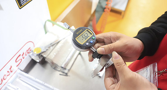
The inspection stage is crucial for verifying the compliance of the manufactured parts with the GD&T requirements. Proper inspection methods and equipment should be employed to measure the dimensions and geometric characteristics accurately.
The use of coordinate measuring machines (CMMs) and other advanced inspection tools can facilitate precise and efficient measurement. Inspection results should be compared against the GD&T specifications, and any deviations should be analyzed and addressed accordingly.
Conclusion
GD&T is a vital tool in CNC machining, providing a standardized and precise language for defining and communicating the dimensional requirements of parts. By incorporating GD&T principles and symbols, designers can accurately convey the design intent, and manufacturers can produce parts that meet the desired specifications.
The use of GD&T in CNC machining promotes improved communication, increased quality and precision, and cost reduction. It enables efficient manufacturing processes and facilitates accurate inspection and verification.
By embracing GD&T, CNC machining companies can enhance their capabilities, improve customer satisfaction, and deliver high-quality parts that meet the stringent requirements of modern industries.
FAQs
Q1: What is CNC machining?
CNC machining refers to the process of using computer numerical control (CNC) systems to control the operation of machine tools. It involves the precise removal of material from a workpiece to create a desired shape or feature.
Q2: How does GD&T improve manufacturing efficiency?
GD&T improves manufacturing efficiency by providing clear and unambiguous specifications for part features. It eliminates misunderstandings and reduces rework, minimizing production time and costs.
Q3: Can GD&T be applied to any manufacturing process?
Yes, GD&T can be applied to various manufacturing processes, including CNC machining, injection molding, casting, and sheet metal fabrication. It provides a universal language for defining dimensional requirements.
Q4: Are there any international standards for GD&T?
Yes, there are international standards for GD&T, such as ASME Y14.5 and ISO 1101. These standards provide guidelines and rules for the interpretation and application of GD&T symbols and tolerances.
Q5: How can GD&T help in ensuring part interchangeability?
GD&T allows designers to specify the allowable variations in part features, ensuring that interchangeable parts fit together properly. It promotes consistency in the manufacturing process and helps achieve the desired functionality and assembly compatibility.

 +86 15099911516


 Read more