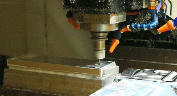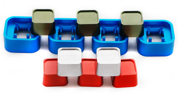
16 years one-stop China custom CNC machining parts factory

Hey there I’m VMT Sam!
With 25 years of CNC machining experience we are committed to helping clients overcome 10000 complex part-processing challenges all to contribute to a better life through intelligent manufacturing. Contact us now
 399 |
Published by VMT at Jul 14 2026 | Reading Time:About 8 minutes
399 |
Published by VMT at Jul 14 2026 | Reading Time:About 8 minutes


A mechanical keyboard case may look accurate in a CAD model but still fail during assembly. Housing deformation, misaligned mounting holes, uneven case gaps, damaged threads, and anodizing color differences can delay approval and increase rework. These risks can be reduced through early DFM review, controlled machining, finishing coordination, and assembly-based inspection.
Note: A CNC machined mechanical keyboard case is a custom housing milled from aluminum, brass, stainless steel, titanium, or engineering plastic. CNC machining supports customized layouts, accurate mounting features, premium finishes, and prototype-to-production development without the tooling investment required for molding or die casting.
This guide explains how keyboard structure, layout, material, tolerances, machining processes, surface finishes, and inspection methods affect the final assembly, appearance, cost, and production stability of your project.
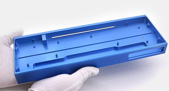
A CNC machined mechanical keyboard case is a custom housing produced from a solid metal or engineering plastic blank according to your 2D drawings and 3D models.
Unlike a standard injection-molded shell, a CNC keyboard case can be customized with:
A complete mechanical keyboard housing assembly may include a top case, bottom case, middle frame, keyboard plate, PCB, gasket, O-ring, daughterboard bracket, weight, badge, knob, spacers, screws, and internal supports.
These parts should not be designed or manufactured as unrelated components. They create one assembly and one connected tolerance chain.
For example, the USB opening may be dimensionally correct relative to the outside of the case but still appear off-center if the daughterboard position is not controlled from the same functional datum. A top case and bottom case may both pass individual inspection but still show an uneven seam if their mating surfaces and locating features are not evaluated together.
Reviewing the complete assembly before machining makes it easier to identify these conflicts while dimensions, datums, and clearances can still be adjusted. This reduces the risk of discovering the problem after the parts have already been anodized, coated, or shipped.
CNC machining is widely used for premium, customized, limited-edition, and low-to-medium-volume mechanical keyboard projects.
It is particularly suitable when your design requires:
CNC machining allows a real metal or plastic prototype to be tested before larger quantities are produced. This is important because some assembly problems are difficult to identify from CAD alone.
A physical prototype can confirm:
If a problem is found during the raw prototype stage, the drawing can usually be adjusted before surface finishing. This prevents an avoidable dimensional change from becoming a finished cosmetic rejection.
When CNC Machining May Not Be the Lowest-Cost Process
CNC machining may not be the lowest-cost long-term method when the structure is simple, the annual quantity is very high, the design is fully stable, and the appearance or tolerance requirements are relatively low.
In these situations, die casting or injection molding may offer a lower unit cost after the tooling investment has been recovered.
However, CNC machining is still frequently used to validate the case, plate, internal structure, and assembly before production tooling begins. A machined prototype can reveal interference, weak mounting features, poor connector alignment, or unsuitable wall thickness before those issues are built into an expensive mold.
Tip: Compare manufacturing methods based on tooling cost, quantity, revision flexibility, appearance, tolerance requirements, and time to market—not unit price alone.
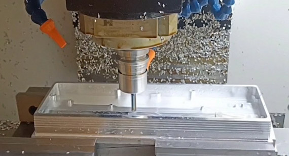
A mechanical keyboard project usually contains several related components. Producing these parts under one engineering and inspection plan can reduce the inconsistencies that often appear when separate suppliers use different datums, material batches, finish standards, and inspection methods.
| Part |
Main Function |
Common Manufacturing Concern |
Machining and Inspection Focus |
Result |
| Top case | Defines the bezel, key opening, plate support, and visible seam | Warping, plate misalignment, surface defects | Flatness, plate position, mating datums, cosmetic inspection | More consistent plate fit and exterior appearance |
| Bottom case | Holds the PCB, bosses, cables, weight, and acoustic cavities | Deformation after heavy material removal | Staged machining, fixture support, free-state inspection | Lower risk of rocking, uneven gaps, and assembly interference |
| Keyboard plate | Supports switches and influences typing feel | Tight switch openings, burrs, poor flatness | Opening dimensions, edge control, hole position, flatness | Easier switch assembly and more stable support |
| Weight | Adds mass, balance, and visual contrast | Loose fit, scratches, poor engraving alignment | Pocket fit, finish preparation, assembly and appearance | Better assembly and premium cosmetic appearance |
| Badge | Provides branding and decorative detail | Uneven surrounding gap or incorrect position | Pocket size, locating features, engraving, finish consistency | Cleaner branding and consistent part alignment |
| Rotary knob | Connects to the encoder | Incorrect bore, rubbing, poor rotation | Bore size, concentricity, shaft fit, rotation clearance | Smooth rotation and better tactile experience |
| Internal bracket | Supports daughterboards or other components | Misaligned holes or insufficient clearance | Datum-based machining, hole position, trial assembly | Reduced internal assembly problems |
| Side frame or strip | Adds structure or decoration | Uneven seams and color differences | Profile alignment, mounting fit, finish coordination | More consistent final product appearance |
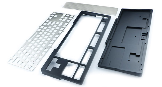
Top Case
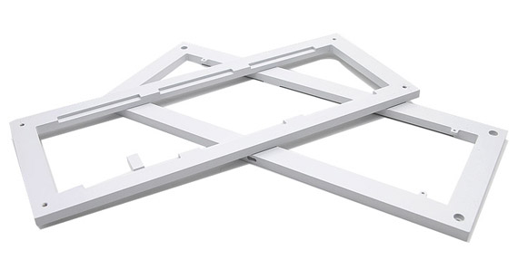
The top case defines the visible bezel, key opening alignment, plate support, corner geometry, and seam between the upper and lower housings.
If the top case is warped, the plate may not sit evenly. If the plate support features shift, the visible key position, gasket compression, or screw engagement may also change. A small flatness problem can therefore affect both appearance and typing structure.
During manufacturing, the plate interface, mating surfaces, and important mounting features should be connected through stable datums. Flatness should be checked after the case is removed from the fixture, not only while it is clamped.
At VMT, visible surfaces are also reviewed before finishing because machining marks that appear minor on raw aluminum may become more obvious after bead blasting or anodizing. Checking the top case before and after finishing helps maintain the intended plate position and exterior seam.
Bottom Case
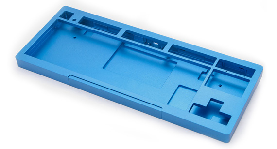
The bottom case often contains the largest machined cavity in the keyboard assembly. It may include:
Removing most of the original material from one side can release residual stress from the blank. The housing may measure correctly while clamped but move after it is removed from the fixture.
If this movement is not controlled, the keyboard may rock on a flat desk, show an uneven side gap, misalign the USB opening, or create interference around the PCB and plate.
A more stable process separates rough and finish machining, balances material removal, controls clamping pressure, and checks the part again in a free state. The case can then enter surface finishing with a more reliable shape and a stable reference for the top housing and internal components.
Keyboard Plate
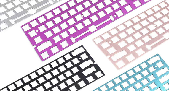
The plate supports the switches and influences structural stiffness, sound, and typing feel.
Common plate materials include:
Switch openings that are too small can make installation difficult or damage switch clips. Oversized openings may reduce support. Burrs around the openings can scratch switches or interfere with assembly, while poor plate flatness can produce uneven support across the keyboard.
Plate machining should therefore control the switch openings, mounting holes, external profile, burrs, and flatness as one process. When the plate is inspected together with the case and PCB, problems can be found before they become difficult to separate during final assembly.
Weights, Badges, and Decorative Components
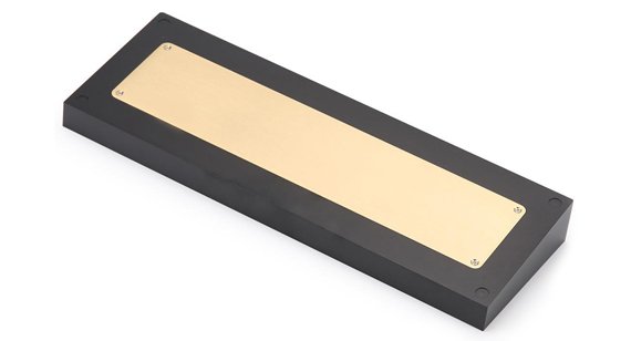
Weights and badges are smaller than the main housing but often have a strong effect on product appearance.
Brass, stainless steel, copper, and titanium weights may be polished, brushed, PVD coated, engraved, or mounted into a precisely machined pocket. If the fit is too tight, the part may not assemble after finishing. If the fit is too loose, a visible gap or movement may appear.
Polished and PVD-coated parts are also highly sensitive to scratches, fingerprints, and edge damage. The machining allowance, surface preparation, finishing thickness, mounting clearance, and packaging method should be planned together.
By checking the fit before coating and protecting the finished surfaces individually, the weight or badge can be installed without forcing the part or damaging the cosmetic finish.
Keyboard layout affects more than the number of keys. It changes the housing length, material blank, cavity size, hole density, fixture design, machining time, and deformation risk.
| Layout |
Typical Structure |
Manufacturing Consideration |
| 40% | Very compact with fewer keys | Tight internal space and closely positioned features |
| 60% | No function row or number pad | Compact cavity with limited PCB and cable clearance |
| 65% | Adds arrow and navigation keys | More openings and mounting relationships |
| 75% | Compact design with function row | Dense features and narrow internal structures |
| TKL | Full keyboard without number pad | Longer housing and increased flatness risk |
| 96% / 1800 | Compact full-size arrangement | Complex PCB, plate, and hole relationships |
| Full-size | Includes complete key set and number pad | Larger blank, longer toolpaths, and higher deformation risk |
Compact Layouts
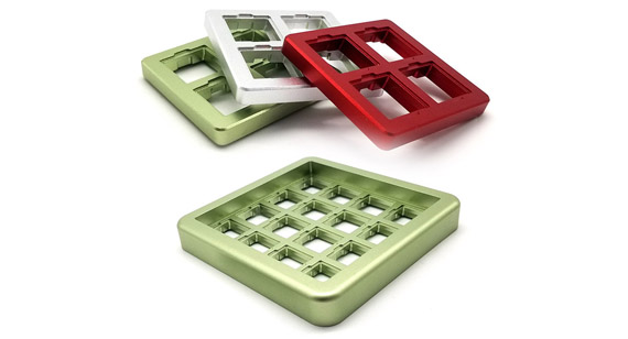
A smaller case does not automatically mean easier or less expensive machining.
Compact 60%, 65%, and 75% cases may contain closely spaced threaded holes, narrow ribs, small internal radii, limited cutter access, and tight PCB clearances.
These features may require smaller tools, lower cutting parameters, and additional inspection. A compact design with complex internal geometry can therefore take longer to machine than a larger but simpler housing.
TKL and Full-Size Layouts
Longer housings increase the importance of material stability, fixture support, long-edge straightness, mating-surface flatness, and protective packaging.
A large cavity may remove a significant percentage of the original blank, increasing the chance of deformation. Long visible surfaces also make waves, color variation, and brushing inconsistencies easier to see.
For TKL and full-size cases, the quotation should consider more than the external dimensions. The internal removal ratio, wall thickness, mounting structure, surface finish, and flatness requirement often have a greater effect on cost.
Tip: Finalize the layout before completing the PCB, plate, mounting system, USB location, and weight design. Changing the layout later can affect nearly every connected component.
The mounting structure determines how the plate, PCB, gasket, and housing are connected. It also affects hole positions, support surfaces, internal clearance, typing feel, and acoustic behavior.
Tray Mount
In a tray-mount keyboard, the PCB or plate assembly is attached to mounting posts in the bottom case.
The post location, height, thread depth, and surrounding clearance must match the PCB and plate. If a post is too high, the PCB may bend when the screws are tightened. If it is too low or incorrectly positioned, the screw may not engage correctly or the PCB may need to be forced into place.
The mounting posts should be evaluated as part of the complete PCB relationship rather than as isolated threaded holes. Machining them from consistent datums and verifying the assembly with the actual PCB can prevent a dimensionally acceptable housing from failing during installation.
Top Mount
A top-mount keyboard normally attaches the plate to the upper housing.
The top case must provide stable support surfaces and accurately positioned mounting holes. If the support surfaces are not level, tightening the screws may distort the plate. If the plate position shifts, it may interfere with the bottom housing or create an uneven visible relationship around the key openings.
Reviewing the top case, plate, PCB, and bottom housing together allows the machining datums and clearances to be based on the real assembly. This provides a more stable plate position and reduces stress when the housing is tightened.
Gasket Mount
Gasket-mount keyboards use silicone, Poron, foam, or another elastomer to support the plate.
The gasket groove directly affects compression and plate movement. A groove that is too deep may provide insufficient support. A groove that is too shallow may overcompress the gasket and prevent the case from closing correctly.
Burrs and sharp edges can cut the gasket or create local pressure points, producing inconsistent support across the keyboard.
Before machining, the gasket material, original thickness, compressed thickness, groove width, groove depth, support height, and plate clearance should be reviewed together. After machining, the groove should be deburred and checked with the actual gasket and plate when available.
This allows the prototype to confirm the real compression condition rather than relying only on nominal gasket dimensions.
Sandwich Mount
A sandwich-mount structure clamps the plate between multiple housing layers.
The design depends on the combined thickness, hole position, and flatness of all stacked components. Even small deviations can accumulate across several layers and cause screw misalignment, uneven pressure, or visible steps between exterior edges.
The complete tolerance chain should be reviewed before machining. Related holes, profiles, and mating surfaces can then be controlled from consistent references, making the assembled layers easier to align.
Bottom Mount
In a bottom-mount structure, the plate is attached to the lower housing.
The plate support, threaded holes, PCB clearance, and top-case clearance should be evaluated as one assembly. If the support is too high, the plate may interfere with the upper housing. If it is too low, the internal spacing or key position may change.
Checking the plate relationship during prototype assembly helps confirm the vertical stack before batch production.
O-Ring Mount
O-ring mounting systems require consistent support geometry and sufficient clearance around the plate and PCB.
The groove or support posts must allow the O-ring to compress evenly without pinching, shifting, or interfering with nearby components.
Providing the O-ring diameter, cross-section, material, hardness, and intended compression allows the groove and support geometry to be reviewed more accurately before machining.
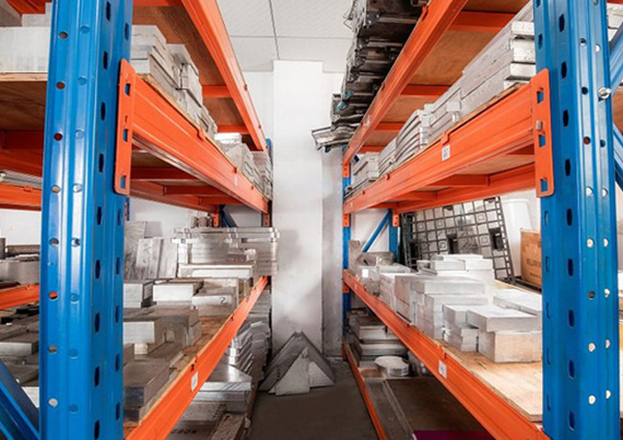
Material choice affects housing weight, stiffness, machining time, surface finish, color consistency, scratch sensitivity, sound, and cost.
| Project Priority |
Suitable Material |
Main Advantage |
Manufacturing Concern |
| Balanced cost and machinability | Aluminum 6061 | Practical for most keyboard cases and finishes | Color consistency still requires process control |
| Decorative anodized appearance | Aluminum 6063 | Good decorative surface potential | Batch and temper consistency |
| Higher strength | Aluminum 7075 | Greater strength than 6061 or 6063 | Higher material and machining cost |
| Heavy premium weight | Brass | Adds mass and decorative contrast | Longer machining time and scratch sensitivity |
| Durable plate or weight | Stainless steel | Strong and wear resistant | Higher cutting force and tool wear |
| Limited-edition component | Titanium | Distinctive appearance and high strength | Difficult and expensive machining |
| Heavy decorative insert | Copper | High density and premium appearance | Soft surface and easy scratching |
| Transparent or softer acoustic design | Polycarbonate | Lightweight and translucent | Heat, scratches, and deformation |
| Plastic plate or insert | POM | Smooth surface and good machinability | Burr and dimensional control |
| Clear decorative housing | Acrylic | Transparent appearance | Chipping and cracking |
Aluminum 6061
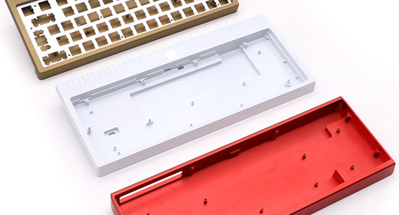
Aluminum 6061 is one of the most practical materials for CNC mechanical keyboard cases.
It offers good machinability, moderate strength, broad availability, and compatibility with bead blasting, anodizing, brushing, polishing, and laser engraving.
It is commonly selected when a project needs a balance between appearance, production cost, structural performance, and repeatability.
However, selecting 6061 does not automatically guarantee consistent anodized color. Material batch, temper, surface roughness, blasting parameters, cleaning, dye conditions, and geometry still affect the final appearance.
Aluminum 6063
Aluminum 6063 is often considered for appearance-focused anodized components.
Its decorative potential can be useful for visible top and bottom cases, but the result still depends on material condition and surface preparation. If matching components are made from different batches or prepared with different blasting standards, color differences may remain visible after anodizing.
For strict cosmetic projects, matching parts should use consistent material and surface-preparation standards, followed by comparison with an approved physical sample.
Aluminum 7075
Aluminum 7075 offers higher strength than 6061 and 6063.
It may be appropriate for high-strength, thin, or premium limited-edition designs, but it also increases material cost, tool wear, and machining difficulty.
Before selecting 7075, it is useful to confirm whether the additional strength is required by the structure. If the choice is based only on material positioning, the project may absorb higher cost without receiving a meaningful improvement in assembly or service performance.
Brass
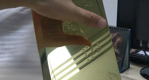
Brass is commonly used for weights, plates, badges, and decorative strips.
It adds mass and visual contrast, but it requires more machining time than aluminum and is sensitive to scratches and fingerprints.
A polished brass weight should be inspected before coating or assembly because surface waves, dents, and machining marks may remain visible after polishing or PVD.
Stainless Steel
Stainless steel is suitable for durable plates, weights, and decorative components.
Its strength and wear resistance are useful, but the higher cutting force and tool wear increase machining time. Thin stainless-steel plates also require flatness and burr control to avoid difficult switch installation or uneven assembly.
Titanium
Titanium is often selected for premium knobs, badges, weights, plates, or limited-edition cases.
It provides a distinctive appearance and good strength-to-weight performance, but heat buildup and tool wear make the machining process more demanding.
The design should avoid unnecessary deep pockets, very small internal radii, and non-functional tight tolerances that increase machining time without improving the finished part.
Engineering Plastics
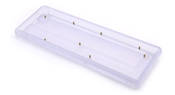
Polycarbonate, POM, and acrylic can be used for cases, plates, spacers, and decorative components.
Plastic parts require controlled cutting heat, chip evacuation, clamping pressure, and surface handling.
Polycarbonate can scratch easily, acrylic may chip or crack, and thin POM features may move after machining. The fixture and machining parameters should be adapted to the material instead of applying the same process used for aluminum.
Material selection should therefore consider the complete case size, wall thickness, mounting structure, surface finish, quantity, appearance standard, and target cost. This prevents an expensive material from being selected where it provides no functional advantage or a decorative material from creating unexpected production risks.
For a deeper comparison of aluminum grades, visit the aluminum keyboard case material guide.
Not every dimension on a keyboard housing needs the same tolerance.
Applying tight tolerances to every feature increases machining time, inspection cost, and rejection risk without necessarily improving the assembly.
A more practical drawing separates features into:
PCB Mounting and Locating Features
PCB mounting holes, locating bosses, and internal clearances determine whether the electronics can be installed without bending or interference.
Clearance holes, locating holes, and threaded holes serve different purposes and should not automatically use the same tolerance.
The PCB model should be included in the assembly review so that mounting points, component heights, cable paths, and connector locations can be checked together.
Plate Positioning Features
The plate position affects switch alignment, visible key opening, gasket support, and the relationship between the plate and PCB.
If the locating features move, the plate may still fit but sit unevenly or create interference around the housing.
The plate should therefore be positioned from functional references that are also related to the housing and PCB.
Top and Bottom Case Datums
The mating surfaces and locating features between the two housings affect the external seam, screw engagement, and final alignment.
If the datums are selected only for machining convenience and not for assembly function, each part may pass inspection while the assembled gap remains inconsistent.
Defining the mating datum, locating method, and acceptable visible gap on the 2D drawing makes the final inspection more meaningful.
USB-C Opening
The USB opening should be positioned relative to the actual PCB or daughterboard connector.
A port opening can meet the exterior dimensions but still look off-center because the connector location was not included in the same tolerance chain.
The opening, daughterboard bracket, PCB position, and external case reference should be evaluated together.
Gasket Grooves
Gasket groove width, depth, corner radius, edge condition, and position influence compression.
The groove should be designed around the real gasket material and compressed condition, not only its original thickness.
If the actual gasket or material data is available during prototype production, the support can be tested before the design is released for batch manufacturing.
Weight and Badge Pockets
Weights and badges may use screws, magnets, adhesive, locating pins, or press fits.
The mounting clearance must account for anodizing, plating, polishing, or PVD coating. A pocket designed with no finishing allowance may fit during raw machining but fail after the surface process.
Knob Bore and Encoder Position
The knob bore, encoder shaft, housing opening, and surrounding clearance affect rotation and visible alignment.
If the bore is too tight, the knob may not install correctly. If the encoder position shifts, the knob may rub against the case even when the knob itself is within tolerance.
The bore and housing opening should therefore be checked as one rotational assembly.
Threaded Holes
Small threaded holes are common in keyboard cases, but thin walls and narrow bosses can make them vulnerable.
The thread size, engagement length, boss diameter, hole depth, screw material, and surface finish should be reviewed together.
Threads placed too close to an edge may break through. Insufficient depth may reduce engagement, while excessive depth may enter another cavity. Residual chips can also cause screws to bind during final assembly.
Threads should be cleaned and checked with suitable gauges or assembly screws before finishing and again afterward where coating or masking may affect the fit.
Where Tight Tolerances May Not Be Necessary
Depending on the function, more economical general tolerances may be suitable for:
Separating critical and non-critical dimensions allows machining and inspection effort to focus on the features that determine fit, alignment, and movement.
DFM Tip: Mark critical dimensions and functional datums clearly on the 2D drawing. A 3D model shows shape, but it does not always communicate which dimensions determine assembly success.
Many machining and assembly problems begin in the drawing. Correcting them before the first prototype is usually faster and less expensive than reworking finished parts.
Designing Sharp Internal Corners
CNC end mills produce internal radii.
If every internal corner is designed as perfectly sharp, the part may require smaller tools, longer toolpaths, EDM, or an additional process.
Adding a practical internal radius often reduces machining time without changing the visible appearance or assembly function.
Insufficient Material Around Threads
A threaded hole placed too close to a thin wall may break through, deform, or strip during assembly.
The boss diameter and wall thickness should be reviewed with the screw size and required engagement length.
USB Opening Not Connected to the PCB Datum
If the opening is dimensioned only from the outside case, tolerance accumulation may shift the visible connector position.
The case, PCB, daughterboard, and connector should be included in the same assembly review.
No Defined Case Gap
If the drawing does not define the acceptable seam between the top and bottom cases, both parts may pass individual inspection without meeting the intended exterior appearance.
The acceptable gap, step, and edge alignment should be defined where the seam is visible.
Gasket Groove Designed Without Compression Data
A gasket groove based only on the original gasket thickness may create insufficient or excessive compression.
The gasket material, hardness, original thickness, compressed thickness, and support area should be considered before the groove depth is finalized.
Ignoring Surface Finish Thickness
Anodizing, plating, powder coating, and PVD may influence holes, threads, press fits, sliding fits, and electrical contact areas.
Critical features may require allowance or masking so that the finished part—not only the raw machined part—meets the assembly requirement.
Tight Tolerances on Every Dimension
Unnecessary tight tolerances increase machining and inspection time and may raise the rejection rate without improving function.
Critical dimensions should be identified according to actual assembly and movement.
Cosmetic Surfaces Not Marked
Without A, B, and non-visible surface definitions, the supplier may not know where fixture marks, hanging points, minor scratches, or color variation are acceptable.
Defining visible surfaces makes finishing and inspection standards clearer.
No Assembly Clearance for Weights or Badges
A decorative insert designed with zero clearance may not fit after finishing.
The assembly method and coating thickness should be included in the pocket and insert tolerance.
No Allowance for Deburring
USB openings, gasket grooves, switch openings, and internal pockets require edge breaking.
If no space is available for deburring, the finished edge may remain sharp or the edge-breaking process may change a critical dimension.
Flatness and Warping
Mechanical keyboard housings are often long, thin, and heavily pocketed.
When a large internal cavity is removed from a thick blank, the residual stress in the material may be released. Excessive clamping force, uneven material removal, cutting heat, and insufficient support can increase this movement.
A warped bottom case may rock on a desk, create an uneven exterior seam, shift the USB opening, or change the pressure on the plate and gasket.
Because the housing becomes difficult to correct after anodizing, flatness should be controlled before finishing and checked again afterward.
At VMT, large pockets can be rough machined in stages, leaving material for later finishing. Support points and clamping forces are selected to avoid forcing the part into a temporary shape. The housing is then checked after release from the fixture so that the measured condition reflects the real assembly state.
Thin-Wall Deformation
Thin side walls and internal ribs may move under cutting or clamping force.
A wall can measure correctly while the part is clamped and then change after release. This can shift exterior dimensions, reduce internal clearance, or misalign screw bosses.
The machining sequence, support method, toolpath, and cutting parameters should be adjusted to reduce force on the thin structure. Intermediate inspection can identify movement before the remaining features are finished.
Hole Position Accumulation
The PCB, plate, daughterboard, housing, weight, badge, and internal brackets may contain related holes.
If each group of holes is machined from a different reference, small errors can accumulate across the assembly. The screws may then feel tight, the PCB may need to be forced into place, or the USB connector may shift from the center of the opening.
Related features should be connected through functional datums. Where practical, important holes and locating features can be completed in the same setup or checked with the mating parts.
Uneven Top and Bottom Case Gaps
An uneven seam may result from warped mating surfaces, inconsistent locating features, screw sequence, surface treatment thickness, or mismatched datums.
Even if the keyboard functions correctly, an uneven visible gap can make a premium product appear poorly manufactured.
Inspecting only the individual top and bottom cases is therefore not enough. The assembled seam should also be checked after machining and finishing.
Burrs Around Openings and Grooves
Burrs may remain around:
These burrs can damage cables, cut gaskets, scratch the PCB, interfere with switches, or prevent screws from seating correctly.
Burr control begins with tool condition, cutting direction, and machining parameters. Controlled deburring, chamfering, edge breaking, cleaning, and visual inspection are then used according to the function of each edge.
Thread Quality Problems
Small threads may fail because of poor chip removal, insufficient depth, thin surrounding walls, tool wear, or finishing buildup.
A damaged thread can make an otherwise completed anodized case unusable. Repair may also create visible damage or reduce the reliability of repeated assembly.
Thread design, machining, cleaning, and inspection should therefore be included in the process plan instead of being treated as a minor secondary feature.
Tool Marks and Surface Defects
Cutter lines, vibration marks, uneven roughness, or reworked areas may become more visible after bead blasting or anodizing.
Surface finishing cannot reliably hide deep machining defects. In some cases, it makes them easier to see.
Visible surfaces should be inspected under suitable lighting before finishing. Any rework should be completed using a controlled method so that the corrected area does not develop a different texture or color.
Anodizing Color Differences
Color differences may result from:
The top and bottom cases may meet every dimensional requirement and still be rejected if they do not visually match.
Color control must therefore begin with material selection and surface preparation. Matching parts should use consistent raw material, machining texture, blasting standards, and finishing conditions whenever possible.
Scratches During Handling
Large flat housings and polished weights can be damaged during machining, deburring, cleaning, transport, surface finishing, inspection, assembly, or packaging.
Waiting until final inspection to identify scratches does not prevent the loss of a completed part.
Separating components, protecting visible surfaces, and controlling contact between parts throughout the process reduces the chance of cosmetic damage before shipping.
A stable keyboard case cannot be created through final inspection alone. Design review, fixture planning, machining, finishing, inspection, and assembly validation need to work as one connected process.
Engineering and DFM Review
Before machining, VMT reviews the keyboard layout, mounting structure, material, wall thickness, datums, critical dimensions, hole relationships, threads, finishing requirements, and complete assembly.
This review may identify:
Finding these issues before programming begins allows the drawing to be adjusted while the cost of change is still low.
Fixture and Machining Planning
The fixture must hold the part securely without creating a false shape.
For large or thin-wall housings, support-point location, clamping-force distribution, datum repeatability, soft jaws, secondary support, and free-state movement are reviewed before production.
Large pockets may be rough machined in stages, while finishing material is retained until the part has stabilized. Related features can be completed from consistent references to reduce repeated positioning error.
This creates a more stable housing before finishing and a more reliable foundation for the PCB, plate, and mating case.
Datum and Tolerance Management
Critical features such as PCB holes, plate position, USB openings, gasket supports, weight pockets, and housing interfaces should not be controlled independently.
VMT identifies the functional relationships and uses datums that reflect the way the parts assemble. Important dimensions are then checked during production instead of waiting until every machining step has been completed.
This makes it easier to correct tool wear or dimensional drift before additional work and surface finishing are added.
Surface Preparation and Finish Coordination
Before surface treatment, the parts are checked for tool marks, burrs, dents, flatness, threads, mating features, and cosmetic defects.
For matching components, material batches, surface roughness, blasting standards, color samples, part orientation, and handling requirements are coordinated.
This reduces the chance of discovering visible machining marks, inconsistent textures, or color differences after the finishing cost has already been added.
Inspection and Assembly Validation
Dimensional reports are important, but they do not always reveal how several parts behave together.
When mating components are available, VMT can check:
Assembly validation can identify interference or tolerance accumulation that is difficult to detect from one component’s inspection report.
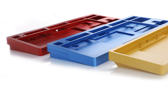
Surface finishing affects corrosion resistance, texture, color, wear resistance, dimensional fit, and the perceived quality of the completed keyboard.
| Surface Finish |
Suitable Materials |
Typical Appearance |
Main Production Concern |
| Bead blasting | Aluminum, stainless steel, titanium | Uniform matte texture | Uneven blasting or directional marks |
| Clear anodizing | Aluminum | Natural metallic finish | Material and surface consistency |
| Black anodizing | Aluminum | Dark premium appearance | Color depth and scratch protection |
| Color anodizing | Aluminum | Custom product colors | Batch-to-batch color variation |
| Hard anodizing | Aluminum | Wear-resistant functional finish | Thickness and dimensional influence |
| Brushing | Aluminum, brass, stainless steel | Directional metal grain | Grain direction and handling scratches |
| Polishing | Aluminum, brass, stainless steel | Reflective finish | Waves, dents, edge rounding, fingerprints |
| PVD coating | Brass, stainless steel, titanium | Decorative metallic colors | Surface preparation and coating uniformity |
| Powder coating | Aluminum and steel | Broad color range | Coating thickness and edge buildup |
| Laser engraving | Most metals | Logos and product information | Position, contrast, and heat marks |
Bead Blasting and Anodizing
Bead blasting followed by anodizing is widely used for aluminum keyboard cases.
The bead blasting creates a matte texture, while anodizing provides color and corrosion resistance.
However, the anodizing bath cannot correct inconsistent machining or blasting. If one component has a different surface roughness, media exposure, or material batch, the final color may appear different even when both parts are processed together.
Matching top and bottom cases should therefore use the same surface-preparation standard and be compared with an approved physical sample.
Brushing
Brushing creates a directional grain.
When several brushed parts are assembled together, the grain direction should be specified on the drawing. Different brushing directions can make aligned parts look inconsistent.
The visible grain should also be protected during later assembly and packaging because local scratches are difficult to blend without changing the texture.
Polishing
Polishing creates a reflective finish but can reveal surface waves, dents, and edge rounding.
A polished weight or badge should be inspected before PVD or final assembly. If a defect remains underneath the coating, it may still be visible afterward.
PVD Coating
PVD can provide decorative colors and wear resistance for brass, stainless steel, and titanium parts.
The result depends heavily on the pre-coating surface. Brushing lines, polishing marks, dents, or contamination can remain visible through the final coating.
The raw surface should therefore be approved before coating begins.
Laser Engraving
Laser engraving can add logos, model names, serial numbers, and decorative patterns.
The engraving position should be referenced to visible edges or locating features. This prevents branding from appearing shifted even when the engraving dimensions themselves are correct.
Surface Finish Design Considerations
Surface finishing should be considered during the design stage.
The drawing may need to define:
Tip: Surface treatment cannot hide deep tool marks, dents, or uneven machining. These defects may become more visible after anodizing or PVD.
For more information about aluminum color and finish control, visit the keyboard case anodizing guide.
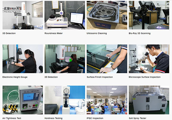
Inspection should follow the manufacturing risk and the stage at which a problem can still be corrected.
Inspection Before Surface Finishing
Before anodizing, plating, or coating, VMT checks features that would be difficult or expensive to repair later.
These may include:
If a dimensional problem is found at this stage, the part may still be corrected without wasting the finishing process.
Inspection After Surface Finishing
Finished parts are checked again because anodizing, plating, coating, masking, handling, and cleaning can affect the final condition.
Post-finish inspection may include:
A part that passed raw dimensional inspection may still fail after finishing if the coating changes a fit, a thread becomes blocked, or a cosmetic surface is damaged.
Inspection Before Shipping
Final checks may include:
Large anodized housings, polished weights, and coated decorative parts should not contact each other during transportation.
Depending on the feature and drawing requirement, inspection equipment may include a coordinate measuring machine, height gauge, calipers, micrometers, pin gauges, thread gauges, surface plate, dial indicator, and optical measurement equipment.
The purpose is not simply to use more equipment. The important point is to inspect the correct feature at the stage when a problem can still be prevented from moving into the next process.
The cost of a keyboard case is determined by the complete manufacturing process rather than the external size alone.
Material and Blank Size
Aluminum 6061 is generally more economical than aluminum 7075, brass, stainless steel, or titanium.
A thick blank with a deep internal cavity also creates more material waste and longer rough-machining time.
Material Removal
A lightweight case may be more expensive than a heavier design if most of the original blank must be removed.
Large and deep pockets increase toolpath length, cutting time, chip removal, and deformation risk.
Wall Thickness
Thin walls require lower cutting forces, controlled clamping, additional support, staged machining, and more inspection.
Reducing wall thickness may save a small amount of finished weight but increase machining time and rejection risk.
Case Size
TKL and full-size cases require larger raw material, longer toolpaths, more fixture support, and larger finishing capacity.
Long visible surfaces also require more cosmetic protection during handling and shipping.
Complex Features
Cost can increase with:
Tolerances
Tight tolerances increase programming, machining, tool-control, and inspection requirements.
The most economical drawing applies tight tolerances only where they influence assembly, alignment, movement, or visible gaps.
Surface Finish
Standard bead blasting and anodizing are generally more economical than multi-stage polishing, controlled brushing, special masking, PVD coating, custom color development, or multi-color finishing.
Cosmetic Standards
A strict appearance specification may require:
These requirements add preparation, inspection, and handling work.
Quantity
A prototype carries the full cost of programming, setup, fixture preparation, and first article inspection.
Batch production spreads these costs across more parts but may require dedicated fixtures, approved samples, process documentation, pilot production, and standardized packaging.
Reducing Cost Through DFM
Cost reduction should come from design and process improvement rather than removing the controls required for reliable assembly.
Depending on the design, VMT may suggest:
These changes can shorten machining time without altering the visible design or assembly function.
When the top case, bottom case, plate, weight, badge, and knob are produced by different suppliers, each supplier may use different datums, tolerance interpretations, material batches, finish vendors, color standards, and inspection methods.
The individual parts may pass their separate inspections but fail when assembled together.
Typical results include:
When related components are reviewed under one DFM, machining, finishing, and inspection workflow, their relationships can be checked before surface treatment and shipment.
At VMT, the top case, bottom case, plate, weight, badge, knob, and internal components can be evaluated as one assembly. This makes it easier to maintain shared datums, consistent finish standards, and a repeatable process from prototype to production.
Each production stage should answer a different question.
| Stage |
Main Purpose |
| DFM review | Confirm machinability, tolerances, wall thickness, and assembly relationships |
| Raw prototype | Verify dimensions, flatness, structure, and initial fit |
| Finished prototype | Confirm color, texture, and final cosmetic appearance |
| Trial assembly | Verify PCB, plate, gasket, USB, screws, weight, badge, and knob |
| Golden sample | Establish the approved dimensional and cosmetic standard |
| Pilot batch | Confirm fixture, machining, finishing, and inspection stability |
| Mass production | Maintain repeatability, quality control, packaging, and delivery |
Step 1: Submit Drawings and Assembly Information
Useful project information includes:
Step 2: DFM and Tolerance Review
The design is reviewed for tool access, internal radii, wall thickness, threads, datum selection, tolerance allocation, finishing allowance, and assembly relationships.
Potential problems can then be corrected before material is cut.
Step 3: Material and Finish Confirmation
The material grade, surface texture, color sample, masking, engraving, cosmetic surfaces, and inspection requirements are confirmed.
For strict color matching, a physical sample is more reliable than a digital image.
Step 4: Raw Prototype Machining
The first prototype is machined, deburred, cleaned, and dimensionally inspected.
Where possible, the raw prototype is assembled before finishing. This allows the USB opening, gasket support, mounting holes, or case gap to be corrected without wasting anodizing or coating cost.
Step 5: Finished Prototype
After the raw dimensions and assembly are approved, the prototype receives the required finish.
The finished sample confirms the real color, texture, edge appearance, fit, and handling requirements.
Step 6: Trial Assembly
Available components are assembled to verify:
Step 7: Design Adjustment
If the prototype reveals interference, excessive clearance, poor gasket compression, or cosmetic problems, the drawing and process can be adjusted before production.
Step 8: Golden Sample Approval
An approved sample becomes the reference for dimensions, color, texture, assembly, and packaging.
Step 9: Pilot Batch
A pilot batch verifies whether the machining, finishing, inspection, and packaging process remains stable across multiple parts.
Step 10: Mass Production
After the pilot process is approved, the fixture, program, tool list, inspection points, finishing requirements, and packaging instructions are standardized for repeat production.
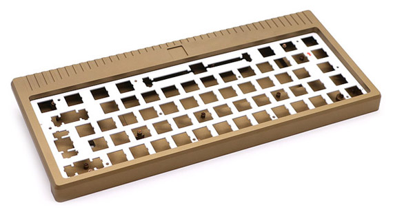
Project Background
A mechanical keyboard brand required a custom aluminum housing assembly for a compact keyboard project.
The assembly included:
The customer needed the PCB and plate to install correctly, the exterior seam to remain consistent, and the anodized top and bottom cases to match closely enough for a premium product.
Project Challenge
The bottom case contained a large internal cavity, leaving relatively thin side walls after material removal.
The main risks were housing deformation, misaligned PCB and plate holes, USB offset, burrs around the gasket features, visible tool marks, and color differences between the two housings.
If these problems were discovered only after anodizing, the customer would have faced higher rework cost and a longer prototype approval cycle.
Manufacturing Approach
VMT reviewed the complete 2D and 3D assembly to identify functional datums, critical holes, thin-wall areas, gasket supports, and visible surfaces.
Rough and finish machining were separated so that the housing could stabilize before the final dimensions were produced. The fixture supported stronger areas of the case and limited pressure on the thin walls.
Related mounting holes and positioning features were machined from controlled references. Critical dimensions were checked during production rather than only after every operation had been completed.
Before anodizing, the raw housings were checked for flatness, hole alignment, threads, gasket grooves, burrs, tool marks, and top-to-bottom fit.
The top and bottom cases were then processed with consistent material and surface-preparation requirements.
Result
The prototype top case, bottom case, plate, and weight assembled with the customer’s PCB and gasket components without forced adjustment.
The mounting holes, USB opening, screw engagement, gasket support, and visible case alignment were verified before the process moved into repeat production.
The approved datum strategy, fixture method, machining sequence, inspection points, finishing requirements, and packaging standard were then transferred to the pilot batch.
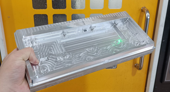
View VMT’s mechanical keyboard shell machining case for more project information.
Providing complete project information makes it easier to identify assembly risks and prepare an accurate quotation.
3D Files
Recommended formats include:
Provide the complete assembly when possible, including:
2D Drawings
The drawing should identify:
Mounting Information
Specify whether the design uses:
Gasket Information
Provide:
Finish and Color Reference
Provide:
Quantity
Separate the expected quantity into:
This makes it easier to select the appropriate prototype, fixture, inspection, and production strategy.
A premium mechanical keyboard case must maintain flatness, align with the PCB and plate, support the selected mounting structure, provide reliable threads, maintain consistent exterior gaps, and remain visually stable after surface finishing.
VMT supports custom CNC machining for mechanical keyboard top cases, bottom cases, plates, weights, badges, knobs, brackets, and complete housing assemblies from prototype validation to repeat production.
Upload your 2D drawings and 3D models to request a quotation and DFM review. The review can cover material selection, wall thickness, internal corners, mounting structure, flatness, hole position, threads, gasket grooves, USB alignment, surface finishing, color consistency, inspection requirements, production cost, and protective packaging.
Request a quote for your custom CNC mechanical keyboard case and receive manufacturing feedback before prototype or batch production.
Send your drawings, requirements, and target quantity. VMT will review your project and provide a machining solution and quote.
1 Tell us what you need
2 Get solution & quote
3 Approve production
Email: inquiry@vimetal.com.cn
1. What is the best material for a CNC mechanical keyboard case?
Aluminum 6061 is a practical choice for many keyboard cases because it offers good machinability, moderate weight, stable mechanical performance, and compatibility with anodizing, bead blasting, brushing, and polishing.
Aluminum 6063 may be considered for appearance-focused anodized parts. Aluminum 7075 provides higher strength but also increases material and machining cost.
Brass, stainless steel, and titanium are more commonly used for weights, plates, badges, knobs, and premium components.
The final choice should consider weight, stiffness, finish, acoustic design, quantity, and budget.
2. Is aluminum 6061 or 6063 better for an anodized keyboard case?
Both alloys can be anodized successfully.
Aluminum 6061 is widely used because it offers balanced machinability, availability, and mechanical properties.
Aluminum 6063 may provide good decorative surface potential, but the final color also depends on material condition, surface roughness, bead blasting, cleaning, bath control, dye conditions, and geometry.
Matching parts should use consistent material batches and an approved physical finish sample when color control is important.
3. What tolerances are required for PCB and plate mounting holes?
The required tolerance depends on the screw size, locating method, PCB clearance, plate structure, mounting system, and number of related components.
Locating holes, clearance holes, and threaded holes should not automatically use the same tolerance.
Providing the complete PCB, plate, and housing assembly allows the manufacturer to review tolerance accumulation and identify possible interference before machining.
4. How can warping be reduced in a long or thin keyboard case?
Warping can be reduced through stable material, appropriate blank preparation, controlled clamping, balanced material removal, staged rough and finish machining, and free-state inspection.
Large internal cavities should not always be completed in one aggressive operation.
Wall thickness, rib design, machining allowance, and fixture support should also be reviewed during DFM.
5. How is the gap between the top and bottom case controlled?
The visible gap depends on the flatness of both housings, locating features, screw positions, mating datums, finish thickness, and assembly sequence.
The related surfaces should be controlled from defined references and checked in the assembled condition before and after finishing.
For premium cosmetic products, the acceptable gap, step, and edge alignment should be shown on the drawing.
6. Can VMT machine gasket-mount keyboard cases?
Yes. VMT can machine top-gasket, bottom-gasket, gasket-sock, and other customized gasket structures according to the provided drawings.
The review includes groove width, groove depth, support height, gasket compression, plate clearance, edge condition, and assembly space.
Providing the gasket material, hardness, and compressed condition improves the accuracy of the DFM review.
7. How are burrs around USB openings and gasket grooves controlled?
Burr control begins with tool selection, cutting direction, tool condition, and machining parameters.
After machining, controlled deburring, chamfering, edge breaking, cleaning, and visual inspection are used according to the function of the edge.
USB openings, gasket grooves, switch profiles, and PCB areas require particular attention because burrs can damage cables, gaskets, switches, and electronic components.
8. How can anodizing color differences be reduced?
Color consistency depends on material grade, material batch, surface roughness, blasting media, blasting pressure, cleaning, anodizing conditions, dye control, part orientation, and inspection lighting.
For matching top and bottom cases, use consistent material, standardized machining and blasting, the same finishing batch where possible, and an approved physical color sample.
9. Can VMT produce one prototype before batch production?
Yes. CNC machining is suitable for one-piece prototypes, engineering samples, pilot batches, and repeat production.
A prototype can verify PCB installation, plate fit, gasket compression, screw positions, USB alignment, knob clearance, housing gaps, and final appearance.
After approval, the fixture, machining, finishing, inspection, and packaging processes can be standardized for production.
10. What information is required for a quotation?
Provide:
Complete information allows potential manufacturing and assembly risks to be identified earlier and makes the quotation more accurate.


 +86 15099911516




 Read more