16 years one-stop China custom CNC machining parts factory

Hey there I’m VMT Sam!
With 25 years of CNC machining experience we are committed to helping clients overcome 10000 complex part-processing challenges all to contribute to a better life through intelligent manufacturing. Contact us now
 10 |
Published by VMT at Jun 30 2026 | Reading Time:About 3 minutes
10 |
Published by VMT at Jun 30 2026 | Reading Time:About 3 minutes


Communications hardware has to deliver signal integrity in real-world conditions. For example, a 5G base station heat sink has to dump heat fast enough to keep RF power amplifiers within spec across 10,000 thermal cycles; or, a satellite transceiver cavity has to hold ±0.02 mm dimensional tolerance so the resonant frequency stays on target; or, a fiber optic connector housing has to align with the ferrule within 0.5 µm concentricity to keep insertion loss below 0.3 dB.
This blog will explain how to prevent above issues about communications CNC machining parts; We break down why material choice sets the RF and thermal ceiling for telecom parts, how tight tolerances translate to signal integrity, and which surface finishes handle EMI shielding and outdoor weathering. Finally, a closing case study demonstrates how we maintained a 0.03 mm mounting surface flatness across 1,000 5G base station heat sinks made of 6061-T6 aluminum.
Material selection for telecom parts is not only about production cost, but also concerned about electrical and thermal performance of the CNC machined communications components. Choosing the wrong material can lead to signal loss, thermal runaway, or field corrosion—failures that often surface years after deployment.
2.1 Aluminum Alloys: The Most Common One for Custom Telecom Parts
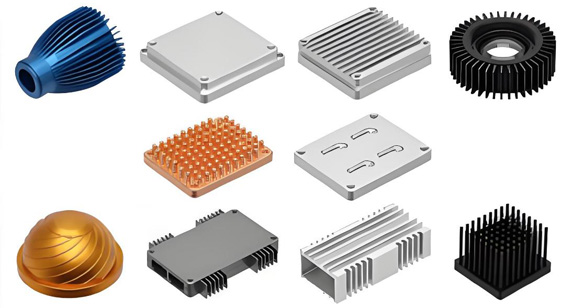
Aluminum alloys carry most of the telecom parts workload because they combine reasonable thermal conductivity, low weight, and CNC-friendly machinability.
Consequently, telecom heat sink radiator machining typically utilizes 6061 for stationary base stations and 7075 for weight-constrained deployments. Both alloys readily accept Type II anodizing in custom colors for branding or environmental coding.
2.2 Copper or Brass: Superior Conductivity for Custom Telecom Parts
Copper and brass deliver electrical and thermal performance that aluminum cannot match, though the trade-offs are increased weight and cost.

2.3 Engineering Plastics(PEEK, or PTFE) : High-frequency Insulation for Custom Telecom Parts
PEEK and PTFE machining for telecommunications provides high-frequency insulation and precise dielectric constant control where metal would otherwise cause signal shorting or reflection.
While the cost of engineering plastics is roughly 5 to 10 times that of aluminum, no metal can substitute for their specific signal-integrity roles.
Clear Material Comparison Table
| Material |
Thermal Conductivity (W/m·K) |
Electrical Conductivity (% IACS) |
Typical Telecom Applications |
| 6061-T6 Aluminum |
167 | 43 | Telecom enclosures, heat sinks, RF housings |
| 7075-T6 Aluminum |
130 | 33 | Antenna mounts, lightweight brackets |
| C11000 Copper |
391 | 100 | High-power waveguides, RF cavity tuning |
| C36000 Brass |
110 | 28 | RF connector bodies, waveguide flanges |
| PEEK |
0.25 | Insulator | Fiber optic insulators, satellite supports |
| PTFE |
0.25 | Insulator | Microwave insulators, high-freq test fixtures |
Tolerance in telecom parts is a critical frequency and signal-integrity specification that the machined geometry must strictly satisfy.
3.1 Why Tight Tolerances Matter for Signal Integrity
Microwave, RF, and 5G signals are highly sensitive to small geometric deviations. A minor 0.02 mm shift in a cavity filter wall can move the resonant frequency by roughly 5 MHz, potentially pushing a bandpass filter out of its allocated channel. Similarly, a 0.005 mm shift in a fiber optic ferrule bore can raise insertion loss by 0.1 dB or more, which is enough to fail a long-haul link budget.
The connection between geometric tolerance and signal behavior is direct and measurable. Tight tolerance CNC machining at ±0.005 mm is the standard for ferrule bores and waveguide cross-sections, while ±0.02 mm is required for RF cavity walls and high-frequency connector mating surfaces. Achieving this level of micron precision typically requires specialized fixturing, climate-controlled environments, and inspection on calibrated CMM equipment.
Surface roughness matters just as much as dimensional tolerance. Microwave waveguide internal surfaces require an Ra of 0.8 µm or better to control insertion loss, as standard machined surfaces at Ra 1.6 µm add noticeable signal attenuation at frequencies above 18 GHz.
3.2 Advanced Machining Capabilities
Meeting these tolerances requires specialized machining expertise.
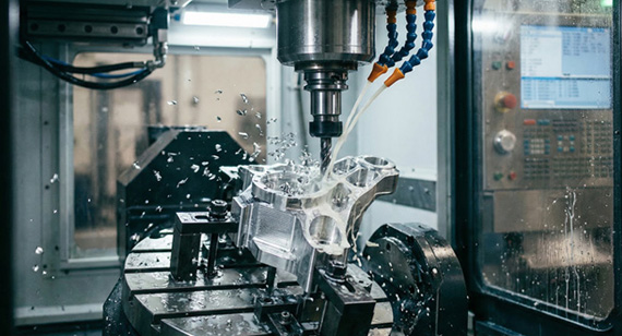
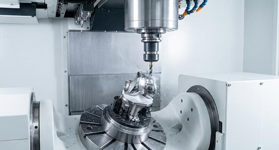
5-axis CNC milling for complex telecom geometries allows operators to handle waveguides, RF cavity filters, and antenna brackets in a single setup. This single-setup machining removes the cumulative tolerance stack-up caused by multiple fixturing operations, which is critical for parts where cavity dimensions interact across different faces.

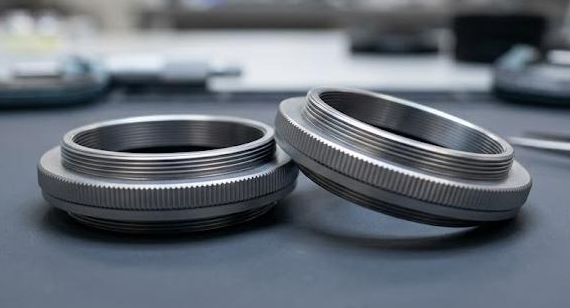
Meanwhile, Swiss CNC turning for miniature telecom pins produces the small-diameter connector pins used in board-mount fiber optic modules and RF test fixtures. It can successfully maintain a ±0.005 mm concentricity on parts with a major diameter below 5 mm.
Finally, CMM inspection with full GD&T callouts verifies these tolerances after machining.

The surface finish on telecom parts serves two roles that often overlap, affecting both electrical performance (EMI shielding, conductivity) and environmental durability (corrosion, weathering). The ideal finish selection depends on which requirement dominates the application.
4.1 EMI Shielding Surface Finishing
Communications hardware must contain radiated energy inside enclosures while excluding external interference. A conductive oxide coating is the standard finish for aluminum RF cavity filter housings. This chromate conversion coating creates a thin conductive layer (typically 0.5 to 2 µm thick) that maintains essential grounding paths. This means, you must choose chromate conversion coating rather than anodized aluminum surfaces to meet shielding and grounding requirements.
Electroless nickel plating serves a dual purpose: it provides robust EMI shielding on RF connector bodies and housings while adding wear resistance for repeated connector mating cycles. Typical plating thickness ranges from 5 to 25 µm, with electrical conductivity maintained through strict phosphorus content control.
Silver plating is reserved for the highest-performance waveguides and satellite RF contacts, where insertion loss at frequencies above 18 GHz must stay below 0.05 dB per connection. While silver's conductivity (106% IACS) outperforms nickel and chromate, its high cost and tarnish sensitivity limit its use to specific critical contact surfaces.
4.2 Corrosion Resistance for CNC Telecom Equipment Parts
Anodized aluminum telecom enclosures utilize Type II anodizing (5 to 15 µm) for outdoor IP65 deployments. This anodized layer is hard, UV-stable, and available in custom colors for branding or functional coding.
Nickel plating for RF connectors successfully combines corrosion resistance with the electrical conductivity that connector bodies require. Also, connector housings and outer contacts typically feature electroless or electrolytic nickel, with the thickness tuned to specific mating cycle requirements.
Passivation for stainless steel telecom parts is applied to 303 and 316 grades used in marine antenna mounts and coastal base station hardware. This process removes free iron from the surface and grows a thin chromium oxide layer that effectively resists pitting corrosion in salt-spray environments.
Clear Surface Finish Comparison Table
| Finish |
EMI Shielding |
Corrosion Resistance |
Typical Application |
| Type II Anodizing |
Low (insulating) | High | Outdoor telecom enclosures, 5G base stations |
| Type III Hard Anodizing |
Low (insulating) | Very high | Wear surfaces, antenna mounting hardware |
| Electroless Nickel Plating |
High | High | RF connector bodies, indoor enclosures |
| Conductive Oxide Coating |
High (60+ dB) | Moderate | RF cavity filter housings, EMI-critical cavities |
| Silver Plating |
Very high | Low (tarnish) | High-frequency waveguide contacts, satellite RF |
| Passivation |
Low (insulator) | High | Stainless steel marine antenna mounts |
5.1 5G Network & Infrastructure
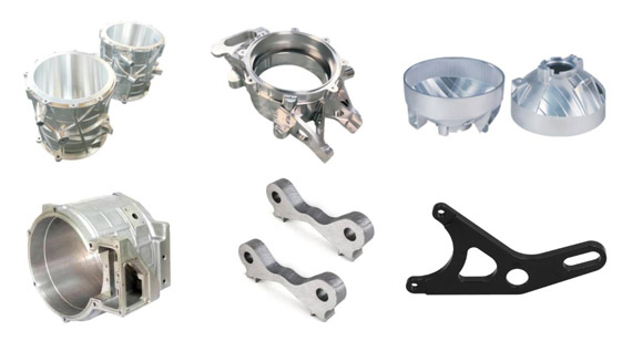
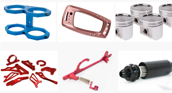
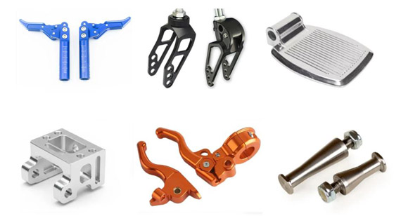
5G base stations, antenna mounts and brackets, and small-cell repeaters form the visible side of the 5G network. CNC machined parts in this category include aluminum heat sinks for RF power amplifiers, anodized aluminum telecom enclosures, and precision mounting brackets for antenna arrays. CNC communication cavity housing and CNC machined RF components round out the RF chain inside base station cabinets.
5.2 RF and Microwave Systems
RF and microwave systems include CNC communication cavity housing for base station filters, couplers and power dividers inside RF chains, and RF testing fixtures and calibration devices for production testing. These parts carry the tightest tolerance requirements in any telecom deployment because their RF behavior depends directly on machined geometry. Microwave waveguides and filters machining in this category includes 10-40 GHz components where surface roughness and dimensional tolerance both determine insertion loss.
5.3 Satellite & Aerospace
Satellite communication parts manufacturing covers signal modules, transponder housings, and ground station hardware. The environment combines vacuum, extreme thermal cycling, and launch vibration loads. Wireless communication device housings for ground stations and signal modules follow the same material and finish standards as the flight hardware they support.
5.4 Data Centers & Networking
Data center server rack parts, switch housings, and high-efficiency cooling plates support the wired side of modern telecommunications. These parts run in temperature-controlled environments, but the thermal loads inside modern data centers push cooling plate performance harder than many outdoor applications.

A telecom equipment OEM required a 5G base station heat sink for its RF power amplifier modules. The component needed to maintain a mounting surface flatness below 0.05 mm for reliable thermal contact, featuring 18 fin slots machined down to a 0.8 mm thickness across a 220 mm × 180 mm footprint. The OEM also mandated Type II anodizing in standard telecom gray alongside full material traceability for carrier certification.
When our engineering team reviewed the initial drawings, two primary manufacturing risks became apparent. First, holding a 0.03 mm flatness across a 220 mm aluminum part is a complex fixturing challenge that requires careful stress relief between the roughing and finishing stages. Second, machining 0.8 mm thick fins at a length of 220 mm without encountering tool chatter requires precise tool selection and optimized feed rates, rather than just generic CNC capabilities.
Specific Solution
We started with a 5-piece prototype run on 5-axis CNC, completing the heat sink body and fin slots in a single setup. Three sample units shipped within 7 working days, with CMM inspection against full GD&T callouts and a surface roughness report. CMM data confirmed 0.025 mm mounting surface flatness, well within the 0.05 mm target.
For production, our team set up pallet-changing CNC with custom vacuum fixturing tuned for the heat sink profile. We ran stress-relief roughing at 60% stock, followed by a finishing pass at 0.2 mm depth of cut to release residual stress before the final flatness pass. Each unit moved through CNC, deburring, anodizing, and final inspection on the same site, with the finishing technician working directly from the engineering drawing at every step.
Result
Across 500 units per batch, mounting surface flatness measured 0.032 mm on average, within the 0.05 mm design tolerance. Fin thickness held within ±0.03 mm across all 18 slots, and anodizing color matched the OEM's telecom gray reference standard. Each batch shipped with material certificates (6061-T6 mill heat number) and full dimensional reports. The OEM passed carrier certification on schedule, and our factory continued to support the next 1,000-unit batch with the same fixtures and inspection routine.

CNC machining delivers the exact precision, material flexibility, and surface finish control that demanding communications equipment programs require. From aluminum telecom enclosures and copper waveguide sections to PEEK-insulated fiber optic components and satellite payload hardware, matching the right material to the right tolerance and finish establishes the performance ceiling for every telecom component.
Whether the project calls for a 5G base station heat sink, an RF cavity filter, a microwave waveguide, or a data center cooling plate, our factory's core objective remains identical: hold the RF tolerance, preserve the surface conductivity, and deliver the exact same EMI performance on the 5,000th unit as we did on the first. Contact our engineering team today to receive expert material recommendations, an RF tolerance analysis, and a competitive quote within 24 hours. [2D drawing(pdf file), 3D drawing(igs/stp/step file)]

Q1: What are communications CNC machining parts?
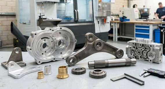
Precision-machined components used in telecom and RF equipment: 5G base station heat sinks, RF cavity filter housings, microwave waveguides, antenna mounts and brackets, fiber optic connector housings, satellite communication parts, data center server rack components, and RF testing fixtures and calibration devices. Typical materials are aluminum (6061, 7075), stainless steel (303, 316), copper, brass, and engineering plastics; typical processes are 5-axis CNC milling, CNC turning, Swiss CNC turning, and turn-mill combination.
Q2: What materials are used in communications CNC machining?
6061 and 7075 aluminum for telecom enclosures, heat sinks, and antenna brackets; C11000 copper for high-power waveguides and RF cavity tuning elements; C36000 brass for RF connector bodies and waveguide flanges; PEEK and PTFE for high-frequency insulation in fiber optic and satellite hardware. Material selection depends on RF frequency, thermal load, environmental exposure, and cost ceiling.
Q3: What tolerances can CNC achieve for communications parts?
±0.02 mm on RF cavity dimensions and waveguide cross-sections, ±0.005 mm on fiber optic ferrule bores for micron-level precision, ±0.05 mm on mounting interfaces. Surface roughness from Ra 0.4 µm (mirror-polished RF surfaces) to Ra 1.6 µm (standard machined surfaces).
Q4: Why are tight tolerances critical for signal integrity?
A 0.02 mm shift in a cavity filter wall moves the resonant frequency by roughly 5 MHz, enough to push a bandpass filter out of its allocated channel. A 0.005 mm shift in a fiber optic ferrule bore can raise insertion loss by 0.1 dB or more. Surface roughness above Ra 0.8 µm adds measurable attenuation at frequencies above 18 GHz.
Q5: What surface finishes are available for communications CNC parts?
Conductive oxide coating (chromate conversion) for RF cavity EMI shielding, electroless nickel plating for RF connector bodies, silver plating for high-frequency waveguide contacts, Type II anodizing for outdoor enclosures, gold plating for satellite and high-reliability RF contacts, passivation for stainless steel parts.
Q6: How quickly can communications CNC prototypes ship?
Standard prototype batches of 1-5 parts ship within 5-7 working days from CAD release, including CNC machining and standard surface finishes. RF-specific parts requiring chromate conversion, silver plating, or electroless nickel take 10-15 working days. DFM analysis and a quote typically arrive within 24 hours.
The technical information and manufacturing advice shared on the VMT website are for general guidance only. While we strive for accuracy, VMT does not guarantee that the processes, tolerances, or material properties mentioned are applicable to every specific project. Any reliance you place on such information is strictly at your own risk. It is the buyer's responsibility to provide definitive engineering specifications for any production orders. Final specifications and service terms shall be subject to the formal contract or quotation confirmed by both parties.

 +86 15099911516


 Read more