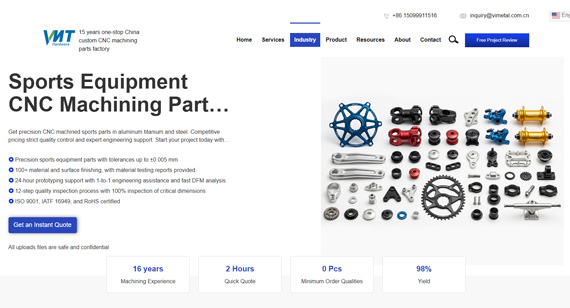
16 years one-stop China custom CNC machining parts factory

Hey there I’m VMT Sam!
With 25 years of CNC machining experience we are committed to helping clients overcome 10000 complex part-processing challenges all to contribute to a better life through intelligent manufacturing. Contact us now
 1 |
Published by VMT at Jul 01 2026 | Reading Time:About 3 minutes
1 |
Published by VMT at Jul 01 2026 | Reading Time:About 3 minutes


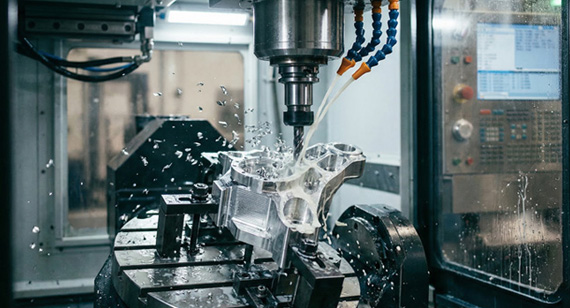
When designing high-end audio gear, such as amplifier chassis, machined knobs, and premium audio sockets, appearance is naturally the primary focus. Audiophiles judge an amplifier by its faceplate texture and knob weight, and CNC machining excels here, delivering tight tolerances and exquisite surface finishes. However, the trap is focusing solely on aesthetics while ignoring the practical feasibility of CNC machining. This factor directly dictates whether custom audio parts can be produced successfully, flawlessly, and cost-effectively.
This blog post provides 5 practical design tips to achieve the perfect balance of precision, appearance, and manufacturing costs. Additionally, the closing case study demonstrates how our factory maintained ±0.02 mm dimensional accuracy across 80 high-end speaker faceplates for a U.S. audio brand, ultimately cutting rework rates by 30%.
A CNC end mill is a rotating cylinder, meaning it cannot produce a perfect 90-degree internal corner. When a drawing calls for a sharp internal corner, it is either to slow the cut dramatically or hand-finish the corner, both of which spike production costs.
The fix is straightforward: specify internal radii that are slightly larger than the cutting tool intended for the job. For example, while a 3 mm end mill leaves a 1.5 mm corner radius, designing for a 3.175 mm (1/8 inch) corner radius allows the cutter to move at its full feed rate. This removes the need for a separate finishing pass and significantly reduces tool wear in deep pockets.
Two practical rules for internal radii:

Material choice for high-quality cnc audio parts comes down to three factors: acoustic resonance, machinability, and surface finish compatibility. Selecting the wrong alloy can result in a chassis that resonates at unwanted frequencies, costs too much to machine, or fails to accept the intended cosmetic finish.
Deep pockets and thin walls cause the majority of CNC audio part failures. While both geometries look flawless in design software, they frequently fail during actual machining.
Deep cavities require long, extended-reach tools. Any pocket deeper than 4 times its width forces the use of a longer end mill, which deflects far more than a standard tool of the same diameter. Tool deflection leads to chatter marks on the walls, dimensional drift at the bottom of the pocket, and mid-cut tool breakage. As a rule of thumb, keep cavity depth to 4 times the cavity width or less (for example, a 20 mm wide pocket should not exceed 80 mm in depth).
Thin walls are highly susceptible to deflecting under cutting pressure. In aluminum, a wall thinner than 0.8 mm will flex as the cutter passes, springing back afterward and leaving the final dimension out of tolerance.
Recommended minimum wall thicknesses:
For audio faceplates, the cosmetic minimum is usually 1.5 mm to ensure absolute flatness after post-processing. Thinner walls tend to warp during the anodizing bath, requiring manual straightening afterward. If a design strictly demands a thin wall or deep pocket, work with the shop to plan for sacrificial support ribs or multi-pass machining with stress-relief stages.

Tight tolerances are the single biggest cost driver in CNC machining. Specifying 20 dimensions at plus or minus 0.02 mm can cost 3 to 5 times more than machining the same part at plus or minus 0.1 mm. This is because tight tolerances mandate slower feeds, additional finishing passes, frequent inspections, and higher scrap rates. The secret to cost-effective design is spending tight tolerances only where they matter.
For audio components, high-tolerance zones are highly predictable:
Everything else—including cosmetic surfaces, ventilation slots, and standard mounting hole patterns—can comfortably run on standard tolerances (plus or minus 0.1 mm is typical for machined aluminum audio gear). Even on a 5000 USD audiophile amplifier, cosmetic features will look identical after anodizing whether they are machined to plus or minus 0.02 mm or plus or minus 0.1 mm. Over-specifying non-mating dimensions does not improve quality; it simply inflates the invoice.
The perceived quality of high-end audio gear lives in its surface finish. However, anodizing, sandblasting, brushing, and powder coating all add measurable thickness to the fabricated part. Type II aluminum anodizing adds 5 to 25 microns per surface, hard anodizing adds 25 to 150 microns, and powder coating can add 50 to 100 microns. These thicknesses accumulate on mating features and can easily push parts out of assembly tolerance.
To prevent assembly failures, maintain strict dimensional specification discipline by explicitly stating on the drawing whether dimensions apply before or after coating:
For audio faceplates, a practical approach is to dimension all features affecting assembly (connector cutouts, mounting holes, chassis mating surfaces) before coating, while dimensioning aesthetic elements (engraved logos, decorative grooves) after coating.
A U.S. audio brand developing high-end bookshelf speakers required CNC machined aluminum faceplates with strict dimensional accuracy across an 80-piece pilot production run. The faceplates measured 180 mm x 120 mm x 8 mm and featured 6 connector cutouts, a tweeter mounting flange, and a brushed anodized finish.

Challenges
The initial prototype run from a previous supplier suffered from two primary defects. First, dimensional deviations in the connector cutout positions caused 35% of the faceplates to fail assembly with the speaker drivers. Out-of-position cutouts forced them to file the openings by hand, damaging the premium anodized finish. Second, batch-to-batch consistency was poor; a 0.05 mm shift in the tweeter mounting flange position between batches meant they could not utilize a unified driver inventory.
The Solution
The Results
Across the 80-piece run, the connector cutout positions averaged a precise plus or minus 0.018 mm, successfully meeting the plus or minus 0.02 mm design tolerance. The assembly success rate surged from 65% to 95%, achieving the brand's target.With batch-to-batch consistency holding the tweeter flange within plus or minus 0.015 mm, the client successfully utilized a single driver inventory across the entire run.

Successful cnc audio parts are won or lost during the design stage. Balancing corner radii, material selection, cavity depths, tolerance mapping, and finishing allowances dictates whether a project ships on schedule or racks up expensive rework fees. Designing with the capabilities of the cutting tool in mind is what separates a problematic lower assembly rate from an outstanding production run.
Ready to take your high-end audio design from prototype to high-volume production? Welcome to submit your files to VMT today, and our engineering team will respond within 24 hours with a comprehensive DFM evaluation, material recommendations, and a transparent quote. [2D drawing(pdf file), 3D drawing(igs/stp/step file)]

Q1: What tolerances are typical for CNC audio parts?
Standard tolerances for cosmetic features typically sit at plus or minus 0.1 mm on machined aluminum. Critical high-tolerance zones, such as connector mating faces and knob shaft bores, require plus or minus 0.02 mm or tighter. General assembly interfaces usually run at plus or minus 0.05 mm.
Q2: Which aluminum alloy is best for an amplifier chassis?
6061-T6 is the default recommendation due to its balanced machinability, excellent anodizing response, and cost-efficiency. 7075-T6 is ideal if structural strength takes priority over finish consistency, while 5052 is chosen if the chassis undergoes post-machining bending or forming.
Q3: How can I avoid chatter marks on audio faceplates?
Chatter marks are caused by excessive tool length, overly aggressive feed rates, or inadequate setup rigidity. To prevent them, keep cavity depths under 4 times their width, utilize sharp single-flute tooling for final aesthetic passes, and drop the feed rate when milling walls thinner than 1.5 mm.
Q4: What surface finish works best for audio components?
Type II Anodizing (5 to 25 microns) is the industry standard for aluminum audio hardware. Hard anodizing (25 to 150 microns) is reserved for high-wear contact surfaces. When specifying brushed finishes, ensure the drawing dimensions account for the physical material removed or shifted by the mechanical brushing texture.
Q5: Are these CNC audio parts RoHS compliant?
Yes. VMT maintains ISO 9001:2015 certification and manufactures fully RoHS and REACH compliant components across our entire audio product catalog. Shipments destined for European and North American audio brands include full compliance documentation and material traceability certificates upon request.
Q6: What is the typical lead time for custom CNC audio parts?
Turnaround times for prototype samples are generally 7 to 10 days. Full production batches ranging from 50 to 200 pieces typically ship within 14 to 21 days. Exact lead times depend on geometry complexity, material allocation, and specialized surface finish treatments. VMT provides a firm lead time commitment with every official quote.
The technical information and manufacturing advice shared on the VMT website are for general guidance only. While we strive for accuracy, VMT does not guarantee that the processes, tolerances, or material properties mentioned are applicable to every specific project. Any reliance you place on such information is strictly at your own risk. It is the buyer's responsibility to provide definitive engineering specifications for any production orders. Final specifications and service terms shall be subject to the formal contract or quotation confirmed by both parties.

 +86 15099911516


 Read more