16 years one-stop China custom CNC machining parts factory

Hey there I’m VMT Sam!
With 25 years of CNC machining experience we are committed to helping clients overcome 10000 complex part-processing challenges all to contribute to a better life through intelligent manufacturing. Contact us now
 467 |
Published by VMT at Jul 28 2026 | Reading Time:About 5 minutes
467 |
Published by VMT at Jul 28 2026 | Reading Time:About 5 minutes


A multi-layer herb grinder may appear simple from the outside, but its performance depends on the interaction of multiple machined, finished, and assembled components.
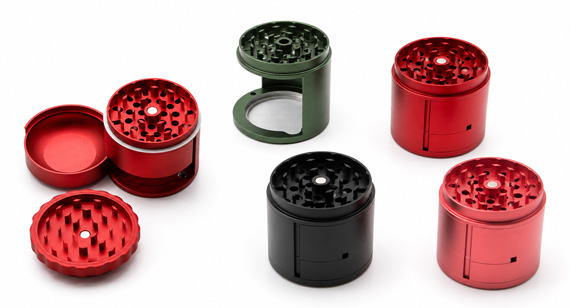
For this rotary-shaft grinder project, the main challenge was not producing one round aluminum component. The challenge was coordinating deep-cavity machining, internal and external diameters, machined teeth, positioning holes, anodizing, magnets, a stainless steel screen, a rotating shaft, a PTFE washer, and the final four-layer assembly.
Any uncontrolled error could create a visible or functional problem:
This case study explains how the project moved from design review to CNC machining, surface finishing, component assembly, and functional inspection.
| Project Item |
Project Detail |
| Product type | Custom rotary-shaft herb grinder |
| Main structure | Four-layer aluminum assembly |
| Primary manufacturing processes | CNC rough milling, CNC turning and precision CNC milling |
| Surface finish | Anodizing |
| Main assembly components | Magnets, stainless steel screen, stainless steel rotating shaft, PTFE washer and retaining components |
| Main manufacturing risks | Chip evacuation, vibration, dimensional instability, concentricity, tool-transition steps, burrs, anodizing color variation and assembly defects |
| Manufacturing objective | Produce a smooth, stable and visually consistent complete assembly based on the customer’s design |
This was not a standard stock grinder project. The components had to be manufactured according to the customer’s design and then verified as one interacting assembly.
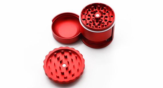
The submitted product design used a four-layer structure with an internal rotating mechanism.
Unlike a conventional two-piece grinder, this design contained additional functional and assembly relationships. The upper and lower components had to align correctly, the internal rotary structure had to move without jamming, and the screen, shaft, magnets and washer had to remain securely positioned after assembly.
The project therefore required more than individual dimensional inspection. VMT needed to understand how the complete product would behave after:
The design review focused on identifying where machining, finishing or assembly variation could affect the final rotation, appearance or structural stability.
Several features made this project more demanding than a conventional round CNC-machined housing.
Deep Internal Cavities
The internal cavity restricted chip evacuation during turning. If aluminum chips remained trapped between the tool and the workpiece, they could interfere with cutting and produce vibration marks or unstable internal dimensions.
Interacting Internal and External Diameters
The internal and external circular features were not independent cosmetic dimensions. They formed part of the rotating and assembled structure.
A small difference in diameter, concentricity or axial position could make the completed assembly too tight, too loose or unstable.
Combined Turning and Milling Operations
The round body and internal chambers were suitable for CNC turning, while the teeth, holes and positioning features required CNC milling.
The transition between these processes had to be controlled so that turning and milling did not leave a visible or functional step.
Multi-Layer Anodized Appearance
The four main aluminum components were viewed together after assembly. Even when each part was acceptable individually, differences in blasting texture, raw material condition, hanging position or anodizing parameters could make the completed set appear inconsistent.
Multi-Component Assembly
Magnets, a screen, a rotating shaft, a washer and retaining components created additional risks that were not visible in the individual CNC drawings.
The assembly process needed to control adhesive quantity, magnet direction, screen retention, shaft position, washer installation and cosmetic protection.
Before machining, the first task was to understand how each component interacted with the other parts.
The engineering review considered:
Reviewing the assembly first helped prevent a common sourcing problem: individual components passing dimensional inspection while the complete product still jams or feels inconsistent.
The next step was to convert the design into a stable manufacturing sequence.
The DFM review focused on five key areas.
Machining Datum Selection
The main circular and rotating features needed consistent datums. Wherever practical, related diameters were planned around the same turning reference to reduce accumulated concentricity errors.
Tool Access
The teeth, deep cavities and internal positioning features required sufficient access for cutting tools.
Tool diameter, tool length and approach direction were considered before confirming the milling strategy.
Chip Evacuation
Because the part contained a deep internal cavity, the process needed to prevent chips from remaining inside the work area during turning.
Surface-Finish Allowance
The anodized layer could influence threads, fitted diameters, shaft positions and other closely matched features.
Pre-finish dimensions therefore had to be considered together with the final assembly requirement.
Assembly Sequence
The magnets, screen, shaft, PTFE washer and retaining components could not be treated as an afterthought.
Their installation sequence and inspection requirements needed to be planned before batch machining.
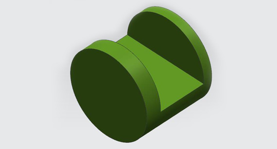
The original process added a rough-milling operation before precision turning.
The purpose of this operation was to create a better path for chip evacuation from the internal cavity.
Without sufficient chip evacuation, aluminum chips could accumulate around the tool during lathe processing. This could cause:
By removing selected material before the main turning operation, the machining team reduced the risk of chips becoming trapped inside the cavity.
This additional operation increased process planning time, but it supported more stable precision turning and reduced the risk of defective internal surfaces.
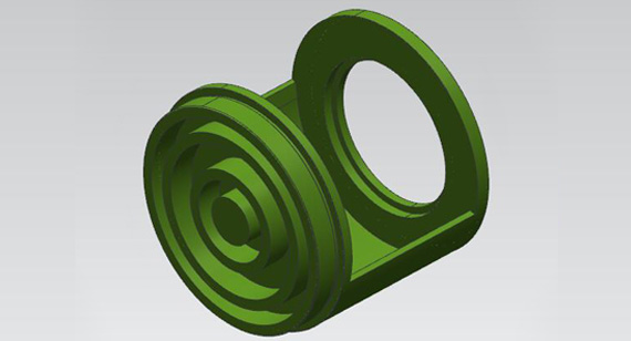
CNC turning was used to establish the primary circular features of the grinder components.
The turning operations included relevant internal chambers, external profiles, end faces, stepped diameters and assembly surfaces.
The most important requirement was not simply achieving a round appearance. The turning process had to maintain the relationship between the inner and outer diameters.
Key controls included:
If the internal or external diameters were produced independently without controlling their relationship, the completed rotary assembly could jam, wobble or generate uneven friction.
For that reason, functional mating dimensions were treated differently from non-critical cosmetic dimensions.
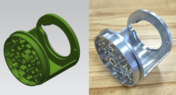
After the main turned features were established, CNC milling was used to produce the grinding teeth and positioning details.
This operation introduced a new challenge: some milled areas overlapped or approached surfaces already produced by CNC turning.
If the machine setup, tool height or coordinate relationship was not controlled, a transition step could appear where the turned and milled surfaces met.
According to the original project record, this transition step was controlled within 0.05 mm. This project-specific value should remain on the published page only after it has been confirmed against the original manufacturing or inspection record.
The milling process also needed to control:
The objective was to form clearly defined teeth without leaving loose burrs or creating excessive edge rounding during later finishing.
After turning and milling, the components required controlled deburring.
The goal was not to make every edge heavily rounded. Excessive deburring could change the tooth profile, reduce edge definition, enlarge small holes or alter the fit between mating components.
The deburring team focused on:
After deburring, the parts were cleaned and inspected before surface finishing.
A pre-finish trial assembly was also important because dimensional corrections are easier and less costly before anodizing.
The trial assembly checked:
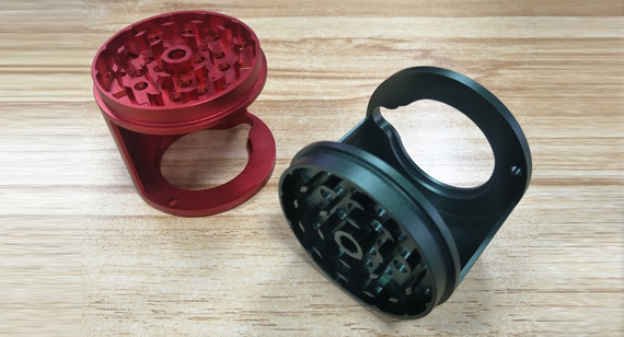
Anodizing provided the required appearance and surface characteristics for the aluminum components, but it also introduced both dimensional and cosmetic risks.
Because this product contained four visible layers, color consistency could not be judged only one part at a time. The parts needed to be inspected as a complete set.
The finishing-control plan considered:
The hanging method was particularly important.
Poor hanging-point selection could leave visible contact marks, while uncontrolled handling during loading, unloading or transport could scratch the finished surfaces.
For a multi-layer product, acceptable individual parts can still create an unacceptable final appearance when assembled together. Therefore, the completed layers should be compared under consistent lighting and orientation.
For more information about available finishing processes, buyers can review VMT’s aluminum surface finishing services.
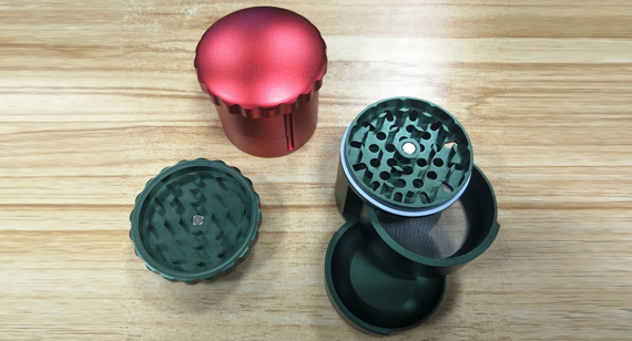
After the anodized components returned from finishing and passed inspection, the project moved into assembly.
The original project included:
These details should be checked against the final approved BOM before publication or repeat production.
Magnet Installation
Magnet assembly required control of:
One of the main risks was adhesive overflow.
Excess adhesive could spread onto visible anodized surfaces or interfere with the surrounding assembly.
To reduce this risk, the assembly method should use a controlled dispensing quantity rather than relying only on operator judgment.
Stainless Steel Screen Installation
The stainless steel screen needed to sit evenly and remain secure after assembly.
Potential problems included:
The screen-retention operation therefore required both visual inspection and a retention check.
Rotating Shaft Installation
The stainless steel shaft was one of the main functional elements of the design.
Its position influenced:
The shaft-related holes, retaining features and assembly direction needed to remain consistent.
PTFE Washer Installation
The PTFE washer helped manage contact between the rotating metal components.
Its thickness, seating position and compression could influence rotational resistance and axial clearance.
An incorrectly installed or missing washer could create direct metal contact, excessive looseness or inconsistent movement.
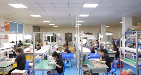
The completed product required more than a standard dimensional inspection of separate parts.
Inspection was divided into three levels.
Individual Component Inspection
Critical dimensions included:
Cosmetic Inspection
The anodized components were checked for:
Complete Assembly Inspection
The final assembly was checked for:
This complete-product inspection was necessary because the user experience depended on the total tolerance stack, not only on one drawing dimension.
| Manufacturing Risk |
Possible Result |
Process Control |
| Chips trapped inside the cavity | Vibration marks and unstable dimensions | Rough-mill chip-relief features before precision turning |
| Inconsistent turning datums | Wobbling or rotational jamming | Machine related circular features from controlled references |
| Poor inner and outer diameter control | Assembly too tight or too loose | Inspect functional mating dimensions and trial-assemble |
| Turning and milling do not align | Visible transition step | Establish shared coordinates and inspect the transition area |
| Tooth-milling burrs | Poor appearance or reduced function | Control tool condition, toolpath and selective deburring |
| Anodizing not included in dimensional planning | Tight shaft or fitted dimensions | Reserve suitable pre-finish allowance and inspect after finishing |
| Different anodized colors between layers | Inconsistent complete-product appearance | Use approved samples and inspect parts as a matched set |
| Poor hanging-point planning | Visible marks or scratches | Define non-visible contact areas before anodizing |
| Excess magnet adhesive | Cosmetic contamination or interference | Standardize adhesive quantity and curing method |
| Incorrect magnet polarity | Weak or reversed closure | Use polarity-controlled assembly instructions |
| Incomplete screen riveting | Loose stainless steel screen | Inspect screen position and retention after assembly |
| Incorrect PTFE washer installation | Unstable rotation or metal contact | Verify washer thickness, position and assembly sequence |
| Individual parts pass but assembly fails | Jamming, wobble or inconsistent feel | Add complete functional assembly testing |
This project shows why a rotary-shaft herb grinder should not be sourced as several unrelated CNC parts.
The product’s final performance depended on the combined control of:
The main value was not simply producing aluminum components that matched isolated dimensions.
The manufacturing process needed to convert the customer’s design into a repeatable assembly in which the parts could rotate, align and maintain a consistent finished appearance.
If your grinder design contains multiple rotating, threaded or assembled layers, consider the following before requesting a quotation.
Provide the Complete Assembly Model
Supplying only separate part drawings can hide interference, tolerance-stack and assembly-sequence problems.
A complete 3D assembly helps the manufacturer review how the components interact.
Identify Functional Dimensions
Not every dimension needs a tight tolerance.
Mark the diameters, shoulders, shaft positions, magnet pockets, screen features and assembly heights that directly affect rotation or fit.
Define the Final Surface Finish Early
Anodizing should be included in the tolerance analysis before machining begins.
Do not finalize close fits based only on raw-machined dimensions.
Define Cosmetic Surfaces
Mark visible Class A surfaces and acceptable hanging, fixture or contact areas.
This helps the factory plan machining, finishing, inspection and packaging.
Provide the Assembly BOM
The BOM should identify:
Approve a Finished Assembly Before Batch Production
An unfinished metal sample cannot fully validate anodized color, coating-related fit, magnet assembly, screen retention or final appearance.
Approval should be based on a finished and assembled sample whenever possible.
After a prototype is approved, the project should be converted into controlled production documents.
These may include:
Without this transfer from prototype knowledge to production control, the same problems may return in later batches even when the first sample is successful.
VMT provides custom CNC turning, CNC milling, surface finishing, inspection and assembly support for customer-designed components.
For herb grinder projects, the manufacturing scope may include:
VMT manufactures according to customer drawings rather than limiting buyers to standard retail products.
The objective is to help your engineering and purchasing teams identify machining, finishing and assembly risks before those risks become delayed samples, inconsistent batches or field complaints.
Send your drawings, requirements, and target quantity. VMT will review your project and provide a machining solution and quote.
All information and uploaded files are secure and confidential.
1 Tell us what you need
2 Get solution & quote
3 Approve production
Email: inquiry@vimetal.com.cn
This page focuses on the manufacturing process of one rotary-shaft grinder project.
For a broader comparison of aluminum, zinc alloy, part structures, CNC machining, die casting and supplier selection, read:
Aluminum vs Zinc Herb Grinders: Parts, Materials, and CNC Manufacturing Guide
Recommended link: https://www.machining-custom.com/blog/spice-herb-weed-grinder-cnc-machining-factory.html
Why Was Rough Milling Added Before CNC Turning?
The rough-milling operation created additional space for aluminum chips to leave the deep internal cavity.
This reduced the risk of trapped chips causing tool deflection, vibration marks and unstable internal dimensions during turning.
Why Must the Inner and Outer Diameters Be Controlled Together?
The inner and outer circular features influence the alignment and clearance of the rotating assembly.
If they are not produced from stable references, the final product may wobble, scrape or jam even when individual diameter measurements appear acceptable.
How Are the Grinder Teeth Machined?
The round bodies and cavities are primarily produced by CNC turning, while the teeth and positioning features are produced by CNC milling.
The milling tool, access direction, tooth spacing and deburring method must be planned together.
Why Can a Step Appear Between Turning and Milling?
Turning and milling use different setups, tools and coordinate systems.
If the two operations are not aligned correctly, a transition step may appear where the machined areas meet.
How Does Anodizing Affect Assembly?
Anodizing changes the aluminum surface and can affect closely fitted diameters, shaft features, threads and other assembly interfaces.
The specified finish and coating thickness should be included in the DFM and tolerance review before machining.
How Can Color Differences Between Four Layers Be Reduced?
Color consistency can be improved by controlling material batches, blasting, cleaning, anodizing parameters, hanging methods and approved color samples.
The four visible components should also be inspected as a matched set.
How Are Magnet Assembly Problems Prevented?
Magnet pockets, polarity, adhesive quantity, seating depth and curing should be controlled through an assembly instruction.
Final inspection should confirm that the magnets are secure and that no adhesive is visible.
How Is the Stainless Steel Screen Secured?
The screen may be retained by a groove, press fit, riveting, retaining ring or another customer-defined structure.
Its position, flatness and retention should be checked after assembly.
Why Is a PTFE Washer Used in a Rotary Assembly?
A PTFE washer can help control contact, friction, noise or axial spacing between rotating components.
Its thickness and position must match the assembly design.
What Files Should Be Provided for a Similar Project?
For an accurate DFM review and quotation, provide:
A successful grinder project requires more than machining each component separately.
Your design must also account for chip evacuation, turning and milling datums, tooth geometry, anodizing allowance, magnet installation, screen retention, shaft alignment and final assembly testing.
Send VMT your 2D drawings, 3D CAD assembly, surface-finish requirements and expected quantity. Our engineering team will review the manufacturing and assembly risks before production.
Whether you are validating a new rotary structure or preparing an approved design for repeat production, VMT can support your project from drawing review and prototype machining to finishing, assembly, inspection and export packaging.
Upload your design files to receive a project-specific manufacturing plan and quotation.


 +86 15099911516




 Read more