15 years one-stop China custom CNC machining parts factory

Hey there I’m VMT Sam!
With 25 years of CNC machining experience we are committed to helping clients overcome 10000 complex part-processing challenges all to contribute to a better life through intelligent manufacturing. Contact us now
 93 |
Published by VMT at Jun 15 2026 | Reading Time:About 2 minutes
93 |
Published by VMT at Jun 15 2026 | Reading Time:About 2 minutes


When a metal part design calls for walls thinner than 2.0 mm, the manufacturing approach must change. Standard machining strategies that work reliably at 5 mm or 10 mm wall thickness begin to introduce chatter, deflection, and dimensional drift. It becomes a ratio problem: when the length or height of a feature is 10×, 20×, or more relative to its thickness, cutting forces bend the wall away from the tool. This produces a surface that tapers, vibrates, or fails to hold tolerance.
CNC machining achieves thin walls down to 0.3–0.5 mm in aluminum with tolerances of ±0.01 mm and Ra 0.4–3.2 µm surface finish, but carries higher per-part cost at volume. Thin-wall casting (die casting, investment casting) reaches 1.0–1.5 mm minimum wall in aluminum at far lower per-part cost above several thousand units, though tolerances widen to ±0.1–0.5 mm and internal porosity reduces mechanical properties. The break-even typically favors CNC below roughly 1,000–3,000 units and casting above that threshold, with many production programs combining both: a near-net-shape casting followed by CNC finish-machining of critical interfaces.
This creates a recurring decision point: at what wall thickness, for what material, and at what production volume does it make more sense to pour metal into a mold rather than cut it from a solid billet? The answer depends on your alloy, tolerance stack, surface finish, and production economics.
This article compares CNC machining and thin-wall casting across these key dimensions to help you find the right process—or the right hybrid approach—for your project.

| Dimension |
CNC Machining |
Thin-Wall Casting |
| Minimum wall thickness (aluminum) |
0.3–0.5 mm | 1.0–1.5 mm (die casting) |
| Dimensional tolerance |
±0.01–0.05 mm | ±0.1–0.5 mm |
| Surface roughness (Ra) |
0.4–3.2 µm | 3.2–12.5 µm |
| Tooling/setup cost |
None (CAM programming only) | $5,000–$50,000+ (die/mold) |
| Best production volume |
1–3,000 units | 3,000+ units |
| Material options |
Wrought alloys (6061-T6, 7075-T6,Ti-6Al-4V, 303/304 SS) | Casting alloys (A356, A380, ADC12, cast iron, cast steel) |
| Internal cavities |
Limited by tool access | Complex internal geometries achievable |
| Mechanical properties |
Superior (no porosity, wrought structure) | Lower (potential porosity, cast grain structure) |
| Design change cost |
CAM reprogram (low) | New die/mold (high) |
In production engineering, a part is considered thin-walled when its wall thickness falls below 2.0 mm, or when the aspect ratio—wall height/length relative to thickness—exceeds 10:1 to 20:1. A 1.0 mm-thick rib standing 15 mm tall, or a cylindrical housing with a 1.5 mm wall and a 60 mm diameter, both qualify as thin-wall geometries.
The core challenge during machining is low stiffness. A thin wall acts like a cantilever beam under cutting forces; the further the tool is from a supported base, the more the wall deflects. This causes the tool to push the wall away during roughing, leading to spring-back and undersized features during the finish pass. It can also excite vibration, leaving chatter marks that ruin surface finish.
For casting, the challenge inverts: the wall must be thick enough for molten metal to fill the cavity before it solidifies. If a wall is too thin, the metal freezes prematurely, causing cold shuts (where two flow fronts meet but fail to fuse) or misruns (unfilled areas).
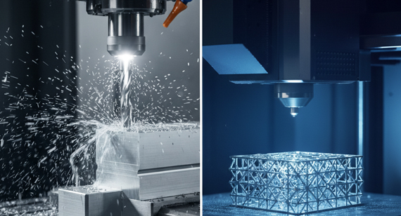
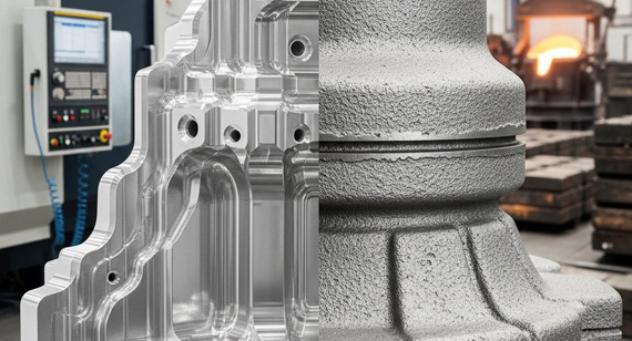
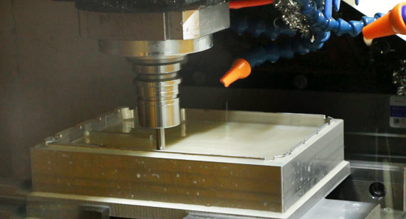
CNC machining is a subtractive process that removes material from a solid wrought blank (plate, bar, or forged billet). This guarantees an internal structure free of the porosity often found in castings.

Advantages of CNC Machining for Thin-Walled Parts
Limitations of CNC Machining for Thin-Walled Parts
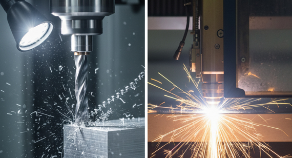
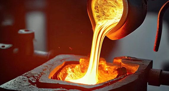
Thin-wall casting is a formative process. The two most common methods for thin walls are die casting (forcing molten metal into steel dies under high pressure) and investment casting (pouring metal into a ceramic shell created from a wax pattern).
Advantages of Casting for Thin-Walled Parts
Limitations of Casting for Thin-Walled Parts
CNC can achieve walls down to 0.3–0.5 mm using specialized vacuum fixtures or back-support compounds. Otherwise, standard soft-jaw setups work fine above 0.5 mm. For casting, aluminum die casting (A380, ADC12) typically tops out at a 1.0–1.5 mm minimum wall thickness due to metal flow limits.
Stainless Steel and Carbon Steel
Steel requires much higher cutting forces, demanding rigid setups and short tool stick-out. The practical minimum wall thickness for CNC-machined stainless steel is 0.5–1.0 mm, and only on short features. For casting, steel’s high melting point and rapid cooling rate in thin cross-sections push the investment casting limit to 2.0–3.0 mm.
Titanium has low thermal conductivity and low elasticity, meaning it concentrates heat and flexes easily under tool pressure. CNC machining thin titanium walls (down to 0.5–1.0 mm) requires light cuts, high speeds, and intense coolant delivery. Crucially, titanium cannot be die-cast because it reacts aggressively with tool steels; it requires specialized vacuum investment casting, making thin-wall titanium castings cost-prohibitive for commercial projects.
Choosing between these processes comes down to balancing upfront tooling against piece-price.

For a typical aluminum electronics enclosure or bracket, the break-even point usually falls between 1,000 and 3,000 units.
The Hybrid Model
You don't have to choose just one. Many successful high-volume programs use a hybrid approach: they cast a near-net-shape blank to get the thin-wall geometry cheaply, then use CNC machining to finish only the critical interfaces like bearing seats, threaded holes, and sealing faces.
A production batch of 5,000 thin-wall aluminum enclosures for a portable medical diagnostic device. The enclosure measured 180 mm × 120 mm × 40 mm with a 1.2 mm main body wall, internal ribs at 0.8 mm, and six mounting bosses requiring ±0.03 mm positional tolerance. The design was locked after prototyping.
The problem: The 50 prototype units were CNC machined from 6061-T6 billet, each taking roughly 45 minutes because the 1.2 mm walls demanded light depth cuts and conservative feed rates to suppress chatter. At the 5,000-unit production forecast, full CNC machining would exceed the project's per-unit cost target. A die-casting-only quote from another supplier offered lower unit cost but guaranteed only ±0.2 mm positional tolerance on the bosses — far outside the ±0.03 mm specification.
The solution: VMT proposed a hybrid manufacturing route. The enclosure body would be produced as a near-net-shape A380 aluminum die casting, with 0.5 mm of machining stock reserved exclusively on the six mounting bosses, the sealing face, and connector cutout edges. VMT managed the die casting coordination and performed all CNC finish-machining in-house — a single fixture, single setup operation locating from cast datum features to machine only the precision interfaces. DFM review confirmed the 0.8 mm internal ribs were within A380's thin-wall flow capability for the given geometry.
The result: The die casting tooling broke even against the full-CNC approach at approximately 800 units. At the full 5,000-unit production volume, the hybrid approach reduced per-part cost by roughly 60% compared to continuing with full CNC machining. Every unit met the ±0.03 mm positional tolerance on all six mounting bosses, verified by CMM inspection with full batch-level dimensional reports. The first production shipment left VMT 10 weeks after die approval.

To pick the right path for your project, ask yourself these four practical questions:
Need an expert review? Upload your 2D/3D drawings (STEP/IGES) for a free DFM assessment. VMT’s engineering team will analyze your wall thickness, tolerance stack, and give you a clear cost comparison for both processes. Contact us today to get started.

Q1: What is the thinnest wall CNC machining can reliably produce?
In aluminum, CNC can reach 0.3–0.5 mm, and in steel/titanium about 0.5–1.0 mm. However, this requires dedicated wall-support fixtures. Without support, standard shop setups will suffer from severe chatter and dimensional drift.
Q2: Why does thin-wall casting have a minimum thickness limit?
It is driven by thermal dynamics. Molten metal loses heat the moment it hits the mold. If the wall channel is too narrow, the metal freezes before completely filling the cavity, causing defects like cold shuts or misruns.
Q3: Are machined parts stronger than cast parts in the same alloy?
Yes. Machined parts inherit the dense, defect-free grain structure of wrought raw materials. Castings naturally suffer from micro-porosity and shrinkage voids during cooling, resulting in lower tensile and fatigue strength.
Q4: Can I switch from CNC to casting later?
Absolutely. It is standard practice to use CNC machining for prototypes and pilot runs to validate the design, then transition to die casting once production volumes scale up and the design locks.
Q5: Can a part combine both processes?
Yes, and it is standard industry practice. This hybrid approach uses casting to form the complex, near-net-shape thin walls at a very low piece-price. CNC machining is then used only to finish critical precision interfaces—such as bearing seats, sealing surfaces, and threaded holes. This strategy captures the high-volume cost benefits of casting while maintaining CNC precision exactly where it matters.
Q6: How does design stability affect the process decision?
It is a critical factor. If your design is still evolving—with shifting dimensions or feature changes—stick to CNC machining. Updating a CNC part only costs a quick CAM reprogram. A casting die, however, is made of hardened steel; modifying it requires welding, heavy re-machining, or entirely scrapping the tool. Until your design is 100% locked, committing to casting tooling introduces high financial and schedule risks.

 +86 15099911516


 Read more