16 years one-stop China custom CNC machining parts factory

Hey there I’m VMT Sam!
With 25 years of CNC machining experience we are committed to helping clients overcome 10000 complex part-processing challenges all to contribute to a better life through intelligent manufacturing. Contact us now
 240 |
Published by VMT at Sep 09 2026 | Reading Time:About 16 minutes
240 |
Published by VMT at Sep 09 2026 | Reading Time:About 16 minutes


CNC Milling Process Step by Step: From Drawing to Finished Custom Part
A CNC milled part can look simple on your drawing, but the manufacturing result depends on far more than running a cutting program. Poor datum planning, unstable fixturing, incorrect machining sequence, or insufficient inspection can cause deformation, dimensional drift, hole-position errors, rough surfaces, and assembly problems. A controlled CNC milling process helps reduce these risks before they reach production.
The CNC milling process typically includes drawing review, DFM analysis, material preparation, machining planning, CAM programming, fixturing, rough machining, semi-finishing, finish machining, in-process inspection, deburring, surface finishing, final inspection, packaging, and shipment.
To show how these steps work together, this guide follows a typical 6061-T6 aluminum CNC milled housing from the first drawing review through machining, inspection, anodizing, and final delivery.
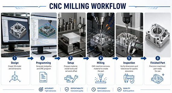
The CNC milling process is the complete manufacturing workflow used to turn your drawing and raw material into a finished machined part. It includes much more than the cutting operation itself.
For a custom part, the process normally begins with a review of your 2D drawing, 3D CAD model, material, tolerances, surface requirements, and production quantity. Engineers then determine the machining strategy, datum structure, fixture method, cutting tools, machining sequence, and inspection plan before CNC programming begins.
A typical workflow looks like this:
Drawing Review → DFM Analysis → Material Preparation → Process Planning → CAM Programming → Fixturing → Rough Machining → Semi-Finishing → Finish Machining → In-Process Inspection → Deburring → Surface Finishing → Final Inspection → Packaging
Each stage affects the next. For example, poor datum planning can lead to hole-position errors after the part is flipped. Excessive clamping force can distort a thin-wall housing. Finishing a critical surface too early may also cause dimensional changes after additional material is removed.
This is why a reliable CNC milling process should be planned around the final functional requirements of your part, not simply around the fastest way to remove material.
In the example used throughout this article, we will follow a 6061-T6 aluminum housing with a main pocket, thin-wall sections, mounting holes, threaded holes, locating features, a flat mating surface, and black anodizing. The goal is to show how each manufacturing decision influences dimensional accuracy, surface quality, assembly, and production consistency.
If you first want to understand CNC milling machines, axis configurations, milling operations, materials, and how the cutting process works, see our What Is CNC Milling guide before continuing with this step-by-step manufacturing workflow.
A complete CNC milling process is a chain of connected manufacturing decisions. Each stage controls a different risk, and problems created early in the process can become more expensive to correct later.
For a custom CNC milled part, the typical workflow is:
| Stage | What Happens | Main Risk Controlled |
|---|---|---|
| 1. Drawing Review | Review the 2D drawing, 3D model, tolerances, GD&T, surface finish, and quantity | Missing requirements or conflicting specifications |
| 2. DFM Analysis | Check wall thickness, deep pockets, internal radii, holes, threads, tolerances, and machining access | Difficult machining, unnecessary cost, deformation, rework |
| 3. Material Preparation | Confirm material grade and condition, then prepare the raw blank | Wrong material, insufficient stock, poor traceability |
| 4. Process Planning | Define datum, machining sequence, machine type, number of setups, and inspection strategy | Tolerance accumulation and inefficient machining |
| 5. Fixture Planning | Select or design workholding, locating points, and clamping positions | Part movement, distortion, poor repeatability |
| 6. CAM Programming | Create toolpaths, select tools, set cutting parameters, and simulate machining | Collision, tool interference, excessive cutting force |
| 7. Machine Setup | Install fixtures and tools, set work coordinates, offsets, and datum | Setup errors and incorrect part location |
| 8. Rough Machining | Remove most of the material while leaving finishing allowance | Excessive heat, cutting force, and material stress |
| 9. Semi-Finishing | Stabilize geometry and prepare critical areas for final machining | Deformation and dimensional drift |
| 10. Repositioning | Flip or relocate the part using machined datums | Position errors and tolerance stack-up |
| 11. Critical Feature Machining | Machine holes, threads, bores, mating surfaces, and locating features | Assembly and functional failure |
| 12. Finish Machining | Bring critical dimensions and surfaces to final requirements | Tolerance, flatness, and surface-finish problems |
| 13. In-Process Inspection | Measure critical dimensions during machining | Defects continuing into later operations |
| 14. Deburring and Cleaning | Remove burrs, chips, and sharp edges | Assembly interference and surface damage |
| 15. Surface Finishing | Perform anodizing, plating, polishing, coating, or other required finishes | Coating thickness, cosmetic defects, dimensional changes |
| 16. Final Inspection | Verify dimensions, GD&T, threads, appearance, and finishing | Nonconforming parts reaching the customer |
| 17. Packaging and Shipment | Protect critical and cosmetic surfaces before delivery | Scratches, dents, and shipping damage |
The important point is that these stages should not be treated independently.
For example, if a thin-wall aluminum housing requires black anodizing, the engineer needs to consider the finishing requirement before machining begins. Thread masking, coating thickness, cosmetic surfaces, mating dimensions, and packaging protection may all influence the machining and inspection plan.
The same is true for precision holes and flat mating surfaces. Their final accuracy depends not only on the finishing pass, but also on the datum strategy, fixture stability, machining sequence, material removal, and in-process inspection used earlier.
Tip: A stable CNC milling process is usually built from the final functional requirements backward. Before deciding how to cut the part, you should first understand which surfaces locate the assembly, which dimensions are critical, and which features must remain stable after finishing.
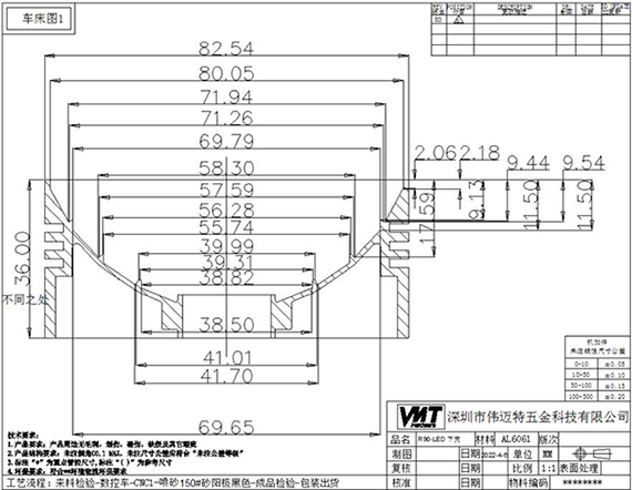
The first step in the CNC milling process is not cutting material. It is understanding exactly what your part must do and how those requirements are communicated in your drawing.
For a custom CNC milled part, the 3D model shows the overall geometry, but the 2D drawing usually contains the manufacturing requirements that determine whether the finished part will assemble and function correctly.
Before production begins, the engineering team should review information such as:
A 3D model can define shape accurately, but it does not always communicate how the part should be inspected or which features are functionally critical.
For example, the model may show two holes in the correct location, but it may not tell the CNC manufacturer:
These details directly affect the machining strategy.
If the drawing does not clearly identify them, a part may still match the 3D geometry but fail during assembly.
For the 6061-T6 aluminum housing used in this guide, the engineering review may identify several features that require special attention:
At this stage, the engineer does not yet decide only which cutter to use.
The more important questions are:
Which surface should become the primary datum?
Which dimensions are critical to assembly?
Which features may deform during material removal?
Which holes must be machined after the part becomes dimensionally stable?
Which dimensions may be affected by anodizing?
These decisions influence nearly every later stage of the CNC milling workflow.
Before machining starts, the drawing should also be checked for possible conflicts.
Common examples include:
If these issues are discovered before programming and setup, they can often be corrected with a small drawing change.
If they are discovered after machining begins, the result may be longer cycle time, additional fixtures, rework, or a new prototype.
Tip: When you send a CNC machining RFQ, provide the 3D model together with the latest 2D drawing whenever possible. Clearly mark critical dimensions, datum relationships, fit requirements, and cosmetic surfaces. This helps the machining supplier focus process control on the features that actually affect your assembly and product performance.
After the drawing and 3D model are understood, the next step is a DFM review. This is where the engineering team checks whether the part can be machined reliably, economically, and repeatedly before CAM programming or fixture design begins.
The goal is not to redesign your part unnecessarily. It is to identify features that may increase machining risk, cost, deformation, or inspection difficulty, then determine whether they should be optimized or controlled through the manufacturing process.
For the 6061-T6 aluminum housing in this example, the DFM review focuses on the features most likely to affect machining stability and final assembly.
Thin walls are common in housings, enclosures, brackets, and lightweight structural parts, but they are also one of the main causes of deformation during CNC milling.
For example, if the housing includes wall sections around 1.5–2.0 mm thick, the engineer must consider:
A thin wall may appear dimensionally correct while the part is still clamped, then move after the fixture is released.
This is why the machining strategy may need to use:
The important point is that wall thickness should be evaluated together with the part size, geometry, tolerance, and material—not as an isolated number.
Deep pockets can significantly increase machining difficulty because the cutting tool must reach farther into the part.
A long tool overhang can cause:
For the aluminum housing, the engineer checks the relationship between pocket depth, tool diameter, internal corner radius, and surrounding walls.
If the design includes a very deep pocket with a small internal radius, the factory may need to use a smaller and longer tool. That may technically make the feature machinable, but it can also make the process slower and less stable.
Where the design allows, increasing the internal corner radius can often improve tool rigidity and reduce machining time.
CNC milling cutters are round, so an internal corner cannot normally be machined as a perfectly sharp 90-degree corner.
If the drawing requires a very small radius such as R0.3 or R0.5 in a deep pocket, the required cutter may be much smaller than the cutter used to remove most of the material.
That can lead to:
If the internal corner is not functionally critical, increasing the radius can often reduce both cost and machining risk.
For assembly pockets, the engineer should also check whether the mating component really requires a sharp internal corner or whether a relief feature could be used instead.
A tight tolerance is only useful when it supports a functional requirement.
During the DFM review, engineers should identify which dimensions affect:
For the example housing, the flat mating surface and locating holes may require much tighter control than an external cosmetic dimension.
The next question is whether the drawing defines these dimensions from the correct datum.
If several critical features are referenced from unrelated surfaces, the machining process may require more setups and create additional tolerance accumulation.
A clearer datum structure can make both machining and inspection more reliable.
Holes and threads may look simple on the drawing, but their depth, position, accessibility, and relationship with nearby geometry can affect the entire machining sequence.
The DFM review should check:
For example, a deep M3 blind thread may require additional drilling depth below the usable thread to provide space for the tap and chips.
If this clearance is not considered, the thread may not reach the required usable depth or the tool may be more likely to break.
Precision locating holes also need different process planning from ordinary clearance holes. They may require drilling followed by reaming or boring, and they are often machined after the part has reached a more stable condition.
Surface requirements also need to be reviewed before machining begins.
A drawing may specify:
These requirements affect toolpath direction, finishing passes, handling, inspection, and even packaging.
For the example aluminum housing, the exterior will be black anodized. That means the machining team must consider in advance:
Surface finishing should therefore be considered during DFM—not after machining is already complete.
No.
Some features should be changed because they create unnecessary cost or manufacturing risk. Others may be functionally necessary and should remain exactly as designed.
The purpose of DFM is to separate these two situations.
A good DFM review should tell you:
This gives you better information before production starts rather than forcing design changes after the first sample fails.
Tip: Do not apply tight tolerances to every dimension unless they are functionally necessary. A tolerance such as ±0.01 mm on non-critical features can increase machining time, inspection effort, fixture complexity, and cost without improving the performance of your assembly.
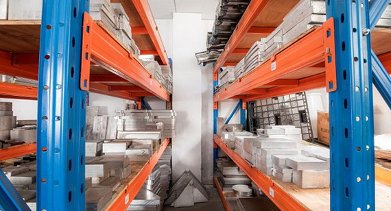
Once the drawing and DFM review are complete, the next step in the CNC milling process is to confirm the correct material and prepare a suitable raw blank.
This step may look simple, but material condition, blank size, stock allowance, and traceability can directly affect machining stability, dimensional accuracy, and final part quality.
For the 6061-T6 aluminum housing used in this example, the factory first confirms that the specified alloy and temper match the drawing requirements before machining begins.
Different aluminum grades can behave differently during machining, anodizing, and assembly.
For example, 6061-T6 is commonly selected because it offers a good balance of:
However, a part specified as 6061-T6 should not simply be replaced with another aluminum grade because it looks similar.
The engineering and material-control teams should confirm:
For projects that require traceability, aerospace-style documentation, or controlled material sourcing, the material certificate or Mill Test Report (MTR) may also need to be retained with the production lot.
Using the wrong material can cause problems that may not be discovered during machining.
For example:
This is why material confirmation should happen before the blank reaches the CNC machine.
The raw material should normally be larger than the finished part.
For example, if the final housing is:
120 × 80 × 25 mm
the raw blank may need additional material around the outside dimensions to allow for:
The exact stock allowance depends on the part geometry, raw-material condition, fixture method, and required tolerance.
Using a blank that is too small can leave insufficient material for final machining. Using a blank that is unnecessarily large increases material cost and machining time because more stock must be removed.
The goal is therefore not simply to choose the largest available block, but to select a blank that provides enough machining allowance without creating unnecessary waste.
Before CNC milling begins, bar, plate, or block material is usually cut to a manageable blank size.
Typical preparation may include:
For some parts, the first CNC operation will then face the material to establish a controlled reference surface.
The raw saw-cut surface itself should generally not be treated as a precision machining datum because it may contain:
Material preparation becomes more important when machining:
An aluminum block may contain residual internal stresses from rolling, extrusion, heat treatment, straightening, or prior processing.
When large amounts of material are removed from one side, these stresses can redistribute and cause the part to move.
For the example housing, a large central pocket removes a significant percentage of the original material. If most of that stock is removed too aggressively from one side, the housing may begin to warp before the finishing operation.
This is one reason the machining process should consider:
Material preparation and machining strategy therefore need to be planned together.
If some raw-material surfaces will remain visible or require a high-quality cosmetic finish, unnecessary scratches and dents should be avoided from the beginning.
Although the example aluminum housing will later receive black anodizing, deep handling marks may still remain visible after surface treatment.
Material should therefore be handled carefully during:
Good cosmetic quality starts before the final finishing process.
For the 6061-T6 housing in this guide, the material-preparation stage may look like this:
At this point, the factory has not yet started the main cavity or housing geometry. The next task is to decide how the part should be machined, including which surfaces come first, how many setups are required, and how the datum structure will be maintained through the complete CNC milling workflow.
Tip: Material cost is not controlled only by choosing a cheaper alloy. Correct blank sizing, nesting, stock allowance, and machining strategy can reduce material waste and unnecessary cutting time while still protecting the dimensions needed for final machining.
After the material and blank are confirmed, the next step is to decide how the part will be machined from start to finish.
This is one of the most important stages in the CNC milling process because the machining sequence directly affects:
A CNC machine can follow a program accurately, but if the machining order is poorly planned, the finished part can still fail.
For the 6061-T6 aluminum housing in this example, the engineer now decides which surfaces should be machined first, how many setups are required, which features should be finished together, and when critical holes should be machined.
The first question is whether the part is best produced on a:
The choice should depend on the actual geometry, tolerance relationships, accessibility, and number of required setups.
For a relatively simple housing with most features accessible from the top and bottom, a 3-axis machine may be enough.
If the part includes several side features, angled surfaces, or critical geometry that would otherwise require repeated repositioning, a 4-axis or 5-axis machine may reduce the number of setups.
The goal is not to use the most advanced machine available. It is to use the machine that provides the best balance of:
Before machining begins, engineers should decide which surfaces and features will be used as references throughout production.
For example, the aluminum housing may use:
These datums define how critical dimensions are established and inspected.
A poor datum strategy can create tolerance accumulation when the part is flipped between setups.
For example, if the top pocket is machined from one temporary reference and the locating holes are later machined from another unrelated surface, the final hole position may shift relative to the mating face.
A better strategy is to create stable reference surfaces early and reuse them through later operations wherever possible.
Most custom CNC milled parts cannot be completed in a single setup.
For the housing in this guide, the process may require:
Setup 1
Machine the first reference surface, rough the main pocket, and create selected top-side features.
Setup 2
Flip the part, locate from the machined datum, and machine the opposite side to control final thickness and flatness.
Setup 3
Machine side holes or other features if they cannot be accessed from the first two setups.
Every additional setup creates potential variation because the part must be:
This means reducing unnecessary setups can improve both accuracy and efficiency.
However, forcing too many operations into one setup can also create problems if the tool cannot access the geometry correctly or if the workholding becomes unstable.
The process should therefore be optimized for stable manufacturing, not simply for the fewest possible setups.
Features with a close tolerance relationship should, where practical, be machined in the same setup.
For example, if two locating holes must maintain tight positional accuracy relative to a mating surface, machining them without repositioning the part can reduce setup-related variation.
The same principle can apply to:
This is especially important when the drawing includes GD&T requirements such as:
Machining related features from the same datum structure makes these requirements easier to control and inspect.
One common mistake is to treat CNC milling as a single cutting stage.
For many precision parts, it is more stable to separate the process into:
Rough Machining → Semi-Finishing → Finish Machining
During roughing, the priority is to remove most of the material efficiently.
During semi-finishing, the geometry is brought closer to final size while the part has an opportunity to stabilize after major material removal.
During finishing, light and controlled cuts are used to achieve the final:
For the aluminum housing, the large pocket should generally not be rough-machined directly to the final wall thickness in one operation.
Leaving finishing stock allows the part to be measured, re-clamped, and corrected before the final dimensions are produced.
Not every feature should be machined as soon as it becomes accessible.
Precision locating holes, bearing bores, and other critical features are often better machined after the main material-removal stages are complete.
Why?
Because rough machining can cause:
If a precision hole is finished too early, its final position may change relative to the rest of the part after additional machining.
For the housing example, ordinary clearance holes may be machined earlier, while precision locating holes can be reserved for a later, more stable stage.
Threads also need to be sequenced carefully to avoid:
The machining sequence should also account for what happens after CNC milling.
For a housing that will be black anodized, engineers may need to plan:
This means the machining plan should be built around the finished part requirement, not only the machined condition.
For the example part, a practical machining sequence might be:
This sequence can change depending on the actual drawing, but the principle remains the same:
The machining order should protect the features that matter most to assembly and final function.
Tip: Do not plan machining only by asking, “Which surface can the tool reach first?” A better question is, “Which sequence gives the part the most stable datum, the least deformation, and the best control of critical dimensions?”
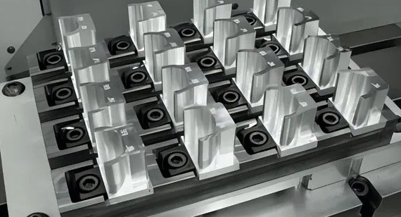
Once the machining sequence is defined, the next step is to determine how the part will be located, supported, and clamped during each setup.
Fixture design is critical because even a perfectly programmed toolpath cannot produce a stable part if the workpiece moves, vibrates, or deforms under clamping force.
For the 6061-T6 aluminum housing in this example, the fixture must hold the part securely while also protecting thin walls, maintaining datum consistency, and allowing access to the required machining areas.
Depending on the part geometry and production quantity, common workholding methods include:
For a simple prototype, a vise or soft jaws may be sufficient.
For repeat production, a dedicated fixture can improve:
The correct fixture should not simply hold the part tightly. It should locate the part consistently and resist cutting forces without distorting the workpiece.
Thin-wall housings are especially sensitive to clamping pressure.
If excessive force is applied to a flexible wall, the part may deform while it is held in the fixture.
The machining result may look correct during inspection on the machine, but after the clamp is released, the wall can spring back and the final dimensions may shift.
This can affect:
For the example aluminum housing, clamping pressure should be applied to stronger structural areas rather than directly onto unsupported thin walls.
Where necessary, the fixture may include additional support points to reduce movement during cutting.
A fixture should locate the part from surfaces or features that are stable and repeatable.
After the first setup, machined surfaces are often more reliable than the original saw-cut blank.
For example, once the housing has a machined datum face, the second setup can use that surface to establish a more consistent reference.
The fixture may then use:
to constrain the part without over-constraining it.
This helps maintain the datum structure established during process planning.
More clamps do not always improve accuracy.
If a fixture forces the part into a shape that it would not naturally hold, the workpiece may deform during clamping and move again after release.
This is especially important for:
The fixture should provide enough support to resist cutting forces while allowing the part to remain in a stable, natural condition.
The fixture must also allow the cutting tool to reach the required features.
Poor fixture design can create problems such as:
For the aluminum housing, the fixture should leave enough space for the tool to machine the main pocket, exterior walls, mounting features, and critical surfaces without unnecessary interference.
This is one reason fixture planning and CAM programming should be coordinated rather than treated as separate tasks.
Soft jaws are often useful for custom CNC milled parts because they can be machined to match the geometry of the workpiece.
Compared with standard vise jaws, properly designed soft jaws can provide:
For the second setup of the aluminum housing, soft jaws may be machined to locate the already processed exterior or reference surfaces.
This allows the part to be flipped while maintaining a stable relationship to the original datum.
A fixture that works for one prototype may not be the best solution for 100, 1,000, or more parts.
For batch production, engineers may optimize the fixture to reduce:
Possible improvements include:
This can improve production consistency while reducing setup time per part.
For the housing in this guide, the fixture strategy may be:
Setup 1
Setup 2
Setup 3, if required
This approach helps maintain a consistent relationship between the original datum, finished walls, holes, and mating surfaces.
Fixture problems often appear as machining problems, even when the machine and program are correct.
Common symptoms include:
For this reason, workholding is not just a setup task. It is part of the dimensional control strategy.
Tip: Stronger clamping does not automatically mean better machining stability. For thin-wall or precision parts, the best fixture uses the minimum clamping force necessary to resist cutting loads while supporting the part in a stable and repeatable position.
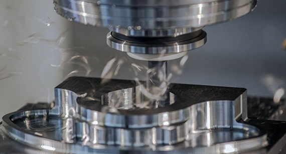
After the fixture and workholding strategy are confirmed, the next step is to convert the part geometry into a controlled machining program.
This is where CAM programming turns the 3D model and process plan into actual tool movements, cutting sequences, spindle speeds, feed rates, depths of cut, tool changes, and machine coordinates.
For the 6061-T6 aluminum housing in this example, the CAM program should not simply remove material as quickly as possible. It must follow the machining strategy already defined for datum control, thin-wall stability, critical features, and final surface quality.
Different features usually require different tools.
A typical tool list for the aluminum housing may include:
Tool selection affects more than cycle time.
The engineer must also consider:
For example, using a very small cutter in a deep pocket may technically reach the geometry, but the longer tool overhang can increase deflection and vibration. A better approach may be to remove most of the material with a larger, more rigid cutter and use the smaller tool only where necessary.
The roughing and finishing stages should normally use different toolpath strategies.
During rough machining, the goal is to remove material efficiently while keeping cutting load stable.
CAM strategies may include:
The program should leave controlled stock on walls and floors rather than cutting directly to final dimensions.
The finishing toolpaths are then created separately to control:
For the aluminum housing, the main pocket may first be rough-machined with a larger end mill, followed by semi-finishing and final wall passes after the part has stabilized.
CAM programming becomes especially important when the part includes thin or flexible features.
If the tool removes too much material from one side of a thin wall, cutting pressure can push the wall away from the tool and create dimensional error.
To reduce this risk, the program may use:
The engineer may also choose to leave temporary support material in some areas during rough machining and remove it later during the finishing stage.
This helps the part retain more rigidity while the majority of the material is being removed.
Cutting parameters need to match the material, cutter, machine rigidity, tool engagement, and required surface quality.
The main parameters include:
For 6061-T6 aluminum, relatively high cutting speeds may be possible compared with harder materials, but this does not mean the maximum available speed should always be used.
If the part includes thin walls, deep pockets, long-reach tools, or cosmetic surfaces, cutting parameters may need to be reduced or adjusted to improve stability.
The correct parameters should balance:
Material removal rate + tool life + dimensional accuracy + surface finish
rather than optimizing only one of these factors.
After a larger tool removes most of the material, some stock may remain in:
Instead of machining the entire feature again with a smaller tool, CAM software can use rest machining to target only the remaining material.
This can reduce:
For complex custom CNC milled parts, this can make the process more efficient without sacrificing detail accuracy.
How a tool enters the material can also affect machining stability.
Depending on the feature, CAM programming may use:
Poor entry strategies can increase cutting load and may lead to:
The same applies to tool exits and finishing lead-in/lead-out movements.
For cosmetic or precision surfaces, the tool should not leave unnecessary dwell marks or abrupt transition lines.
A correct toolpath is not enough if the cutter, holder, spindle, or machine head can collide with the fixture.
The CAM setup should include the actual or representative:
This is especially important when using:
For the aluminum housing, the program must confirm that the cutter can reach the pocket walls and side features without the holder contacting the workpiece or fixture.
Before the program is released to the machine, the machining sequence should be simulated.
The simulation is used to check for problems such as:
For more complex parts, simulation can also verify whether material remaining after one operation will interfere with later operations.
This step reduces the chance of discovering a programming error on the actual machine, where the consequences may include:
For the housing in this guide, the CAM programming sequence may include:
The final program should support the manufacturing plan created earlier rather than override it.
Tip: A shorter CAM program is not automatically a better program. For precision CNC milling, stable tool engagement, controlled cutting forces, safe clearance, and a predictable finishing sequence are often more important than reducing every second of machine movement.
After the CAM program has been verified, the next step is to prepare the CNC machine for production.
This stage connects the digital machining plan with the physical workpiece. Even if the program is correct, errors in fixture installation, tool setup, work coordinates, or datum establishment can cause the entire part to be machined in the wrong position.
For the 6061-T6 aluminum housing in this example, the first setup is used to secure the raw blank, establish a reliable reference surface, and prepare the part for the main roughing operations.
Before loading the workpiece, the machine table, vise, fixture plate, and locating surfaces should be cleaned.
Small chips or contamination trapped under the fixture or workpiece can create alignment errors.
Depending on the tolerance of the part, even a small particle under a locating surface can affect:
The setup process typically includes:
For the example housing, the blank must be held securely enough to resist roughing forces without being distorted before machining begins.
The tools defined in the CAM program are then loaded into the machine.
Each tool must match the programmed:
Tool length and diameter offsets are measured and entered into the CNC control system.
This is especially important when the program includes:
An incorrect tool offset can cause:
The CNC machine needs to know where the part is located in relation to the programmed coordinate system.
This is done by establishing a work offset, commonly using coordinate systems such as:
The exact method may use:
For the first setup, the engineer may define the coordinate system from the raw blank or fixture.
However, the raw surface is only an initial reference.
The more important goal is to machine a controlled surface that can become a stable datum for later operations.
The first machined datum becomes the foundation for the rest of the CNC milling process.
If this surface is inaccurate, unstable, or poorly selected, later operations can inherit the error.
For the housing example, the first machining operation may be to face one side of the blank.
This creates a controlled reference surface that can later be used to establish:
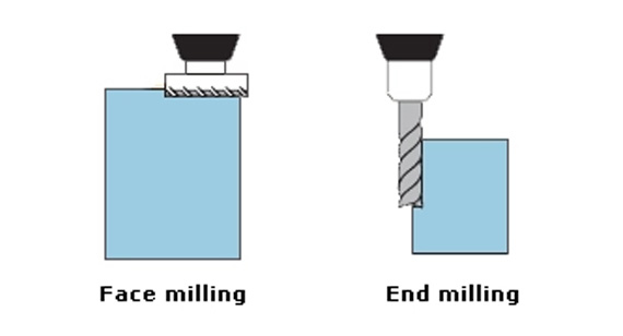
In other words, face milling at this stage is not simply about creating a smooth surface.
Its main purpose is to create a repeatable geometric reference for the next machining steps.
The first facing pass removes the uneven raw surface and creates a consistent plane.
The engineer should consider:
If the raw blank has significant saw-cut variation, it may require more than one controlled pass.
The final reference surface should be stable enough for the next operations and compatible with the datum strategy defined earlier.
Before the machine begins the main roughing cycle, the operator should confirm that:
For a new part or first article, the initial tool movement may also be verified using:
This reduces the risk of a setup mistake causing a collision or scrapping the blank.
After the first reference surface or initial features are machined, selected dimensions should be checked before continuing.
For the aluminum housing, this may include:
If the reference surface does not match the process plan, it is better to stop and correct the setup at this stage than to continue machining the rest of the part from an incorrect datum.
For the first setup of the 6061-T6 housing, the sequence may be:
Once this first datum is established, the part is ready for the next stage: removing most of the raw material while controlling cutting force, heat, and deformation.
Tip: The first datum should be treated as part of the quality-control system, not just as a setup convenience. A stable reference created early in the process makes later repositioning, dimensional inspection, and tolerance control much more reliable.
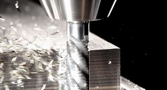
Once the first datum has been established, the CNC milling process moves into rough machining. The goal at this stage is to remove most of the excess material efficiently while keeping the part stable enough for later semi-finishing and finish machining.
For the 6061-T6 aluminum housing in this example, rough machining includes removing the bulk of the material from the main pocket and external geometry while intentionally leaving machining stock on critical walls, floors, and functional surfaces.
Rough machining generates higher cutting forces, more heat, and greater material removal than finishing.
If the main pocket is cut directly to its final wall thickness and depth during roughing, several problems may occur:
For this reason, the roughing stage normally leaves a controlled finishing allowance.
Depending on the part geometry, tolerance, material, and process strategy, an engineer may leave approximately 0.2–0.5 mm of stock on selected surfaces for later semi-finishing or finish machining.
This is not a fixed value for every part. Large housings, thin walls, deep pockets, and high-precision components may require a different allowance.
The order in which material is removed can affect how the part relaxes.
For the aluminum housing, the engineer should avoid removing all material aggressively from one local area while leaving the rest of the blank highly rigid.
A more controlled roughing strategy may gradually open the pocket and reduce material in stages.
The goal is to maintain a reasonable balance between:
This becomes especially important for parts with:
Modern CAM strategies can maintain more consistent cutter engagement during rough machining.
Instead of repeatedly burying the cutter into corners with sudden changes in cutting load, the toolpath can maintain smoother engagement.
This can help reduce:
For the housing, a larger and more rigid end mill can remove most of the pocket material first. Smaller tools should be reserved for areas the larger cutter cannot reach.
This reduces machining time while also improving process stability.
Aluminum machines relatively easily, but large-volume roughing can still generate significant heat.
Heat can affect:
If chips accumulate inside a deep pocket, they may also be recut by the tool, which can damage the cutting edge and leave marks on the part.
The process should therefore maintain effective:
Keeping chips away from the cutting zone becomes increasingly important as the pocket becomes deeper.
For the example housing, the 1.5–2.0 mm wall sections should not be brought to final thickness too early.
A thin wall is much more rigid when some additional material remains around it.
The roughing strategy may therefore:
This allows the part to keep more structural stiffness while the highest cutting forces are being applied.
The thin walls can then be brought closer to final size during semi-finishing and completed during the final finishing stage.
The same principle applies to precision mating surfaces.
For example, if the housing includes a flat mounting face that must mate with another component, it is usually better not to finish that surface during heavy rough machining.
Instead, roughing removes enough material to establish the geometry while preserving stock for a later controlled finishing pass.
This creates an opportunity to correct:
Rough machining places relatively high loads on cutting tools.
Tool wear can gradually affect:
For prototype machining, the operator may visually monitor tool condition and machining sound.
For batch production, tool-life control may be standardized based on:
A worn roughing tool may not immediately make the part out of tolerance, but it can increase cutting force and make thin-wall deformation more difficult to control.
The part does not always need full inspection immediately after roughing, but selected checks can help confirm that the process remains under control.
For the aluminum housing, the operator may check:
This is particularly important during first-article production.
If the part has already moved more than expected after rough machining, the engineer can adjust the semi-finishing or finishing strategy before final dimensions are produced.
For the housing in this guide, the rough-machining sequence may be:
At the end of rough machining, the part should resemble the final geometry, but it should not yet be treated as dimensionally finished.
The next stage is to allow the geometry to stabilize and reduce the remaining stock in a more controlled manner before critical dimensions are completed.
Tip: Faster material removal is only useful if the part remains stable enough to finish accurately. For thin-wall or high-material-removal parts, a slightly more controlled roughing strategy can reduce rework and make the later finishing operations far more predictable.
After rough machining removes most of the material, the part may no longer behave the same way as the original solid blank.
This is an important stage in the CNC milling process because large material removal can release residual stress, reduce part stiffness, and cause the geometry to move. If the part is finished immediately after aggressive roughing, dimensions that look correct in the machine can shift after unclamping.
For the 6061-T6 aluminum housing in this example, this risk is especially important because the part contains a large pocket, thin-wall sections, and a flat mating surface.
Residual stress may already exist in the raw material because of:
While the blank is still thick and rigid, these stresses may remain balanced.
Once a large amount of material is removed, that balance changes.
The part may then experience:
This is why a CNC milled part can measure differently before and after it is released from the fixture.
A thin-wall housing is much less rigid after the main pocket has been roughed out.
For example, a wall that originally formed part of a thick aluminum block may become only 1.5–2.0 mm thick near the final stage.
At that point, the wall can be affected by:
If the wall is finished too early, later operations on the opposite side or surrounding geometry may cause it to move again.
For this reason, critical thin walls are often brought toward final size gradually rather than in one aggressive step.
For parts with a high deformation risk, the machining route may use a staged strategy such as:
Rough Machining → Release → Re-Clamp → Semi-Finishing → Final Finishing
After roughing, the part may be removed or the clamping condition may be relaxed so that the workpiece can settle into a more natural shape.
It can then be re-located from controlled datums and measured again before the next operation.
This gives the machining team a chance to identify movement before the final tolerance is produced.
For the aluminum housing, if the main pocket has caused the part to bow slightly, the semi-finishing stage can correct the geometry while there is still enough material available for adjustment.
Semi-finishing is the stage between rough machining and final finishing.
Its purpose is to:
This is particularly useful for:
Instead of taking the part directly from heavy roughing to a final ±0.01 mm dimension, semi-finishing creates an intermediate stage where the process can be checked and corrected.
Deformation risk can also be reduced by avoiding excessive material removal from only one side when the geometry allows.
For some parts, engineers may alternate machining between surfaces or leave similar amounts of stock around critical areas.
The purpose is not always to create perfectly symmetrical material removal, which may not be possible, but to avoid creating unnecessary stress imbalance.
For example, if one side of a housing is reduced to final thickness while the opposite side still contains significant stock, later machining on the opposite side may cause the finished surface to move.
A more controlled process may leave both sides slightly oversized until the main roughing operations are complete.
After rough machining, the part is less rigid than the original blank.
This means the same clamping force used at the beginning may now be too high.
When the housing is re-clamped, the fixture strategy should be reassessed.
The goal is to:
If a slightly warped part is forced flat in the fixture and then finish-machined, it may spring back again after release.
The final inspection result can then differ significantly from the in-machine measurement.
For the example housing, the main mating surface is functionally important.
Before finishing that surface, the team may check:
If the part has moved, the finishing plan can be adjusted while stock is still available.
This is much safer than discovering flatness failure after the final pass.
Not every aluminum part requires stress-relief treatment.
However, for certain parts with:
a controlled stress-relief or stabilization process may be considered when appropriate for the material and final requirements.
The exact route depends on:
This should be evaluated case by case rather than treated as a standard step for every CNC milled part.
For the housing in this guide, the deformation-control stage may follow this sequence:
The objective is to make the part dimensionally stable before the most critical finishing operations begin.
A prototype that moves slightly after rough machining may be corrected manually.
In batch production, repeated deformation can create:
For this reason, once a stable roughing and semi-finishing strategy is confirmed during prototype validation, the same sequence, fixture conditions, and inspection points should be standardized for repeat production.
Tip: Do not assume that a dimension measured correctly while the part is clamped will remain correct after release. For thin-wall and high-material-removal components, part stability should be checked in a relaxed condition before final machining whenever the tolerance risk justifies it.
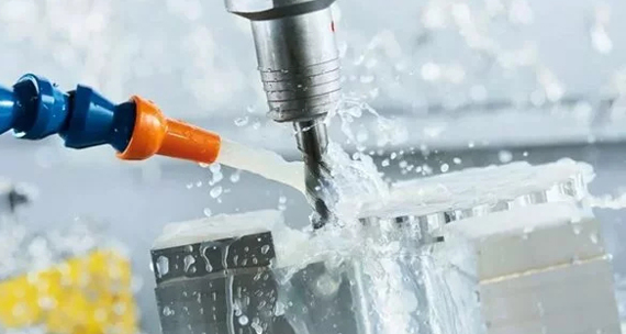
After roughing and semi-finishing, many CNC milled parts need to be flipped, rotated, or relocated so the machine can access the remaining features.
This repositioning stage is one of the most common sources of dimensional error in multi-setup CNC milling. Every time the part is removed and clamped again, the machining process must accurately recover the intended datum relationship.
For the 6061-T6 aluminum housing in this example, the second setup is used to machine the opposite side, control the final overall thickness, and prepare the part for later critical features.
Once a controlled datum has been created, later setups should reference that machined geometry whenever possible.
Machined surfaces are generally more reliable than:
For the housing, the flat reference surface created in the first setup can now be placed against the fixture or soft jaws.
This helps maintain a consistent relationship between:
The goal is to keep all critical dimensions connected to the same datum system throughout the process.
Suppose the housing pocket is machined in Setup 1 and the opposite face is machined in Setup 2.
If the second setup is located inaccurately by even a small amount, that error may affect:
If a third setup is then referenced from another unrelated surface, the errors can continue to accumulate.
This is called tolerance stack-up.
The risk becomes greater when the part requires several independent setups.
A well-planned process reduces this problem by reusing stable datums and machining closely related features in the same setup whenever practical.
After rough machining, the part may have moved slightly because of stress release.
Before using a previously machined surface as a locating datum, the team should confirm that it is still suitable.
Depending on the part, this may involve checking:
If a burr or chip is trapped between the datum and fixture, the entire part can sit at an angle.
This may create errors in every feature machined during the new setup.
Before the part is loaded into the second setup, both the fixture and locating surfaces should be cleaned.
Common contamination includes:
This sounds basic, but precision setup accuracy depends on physical contact between the part and fixture.
A small chip under the workpiece can affect:
For precision work, clean locating surfaces are part of the process control.
The second setup often requires more controlled workholding than the first.
At this stage, the part is closer to its final geometry and may include:
Standard vise jaws may not provide enough support or may damage the part.
For the aluminum housing, machined soft jaws can be shaped to support the external geometry while maintaining a repeatable datum position.
This can help:
For batch production, a dedicated fixture may provide even more consistent positioning.
If the housing has developed slight warpage after rough machining, the operator should avoid simply clamping it flat with excessive force.
Doing so can temporarily hide the deformation.
For example:
The final part may then fail:
The correct response depends on the amount of movement and the tolerance requirement.
Possible actions may include:
Once the part is repositioned, the machine must recover the correct work coordinate system for the new setup.
This may be done using:
The new coordinate system should maintain the intended relationship to the original datum structure.
For production fixtures, the setup may be standardized so that the same locating points and offsets are reused for each part.
This reduces operator-dependent variation.
For the housing example, the second setup may include:
The engineer may still leave small finishing allowances on critical features rather than immediately machining everything to final size.
This is especially useful if later hole machining or additional material removal may affect stability.
For a housing with two important opposite surfaces, Setup 2 often determines the final relationship between them.
The machining team should pay attention to:
These dimensions can affect:
This is why the second setup should be referenced from the functional datum rather than simply from the external shape of the part.
Before moving to later operations, selected dimensions should be checked.
For the aluminum housing, useful checks may include:
If these relationships are correct, the part is ready for the next stage: machining the holes, threads, bores, and other features that depend on the stabilized geometry.
The second setup may proceed as follows:
Tip: Every additional setup introduces another opportunity for positioning error. When two critical features have a tight relationship, machining them from the same datum—and preferably in the same setup—can improve repeatability and reduce tolerance stack-up.
Once the main geometry is stable and the part has been repositioned accurately, the next stage is to machine precision holes, threaded features, bores, countersinks, and other assembly-critical details.
These features often appear simple on the drawing, but they can strongly affect how the finished part fits, aligns, fastens, seals, or moves in the final assembly.
For the 6061-T6 aluminum housing in this example, this stage may include locating holes, M3 threaded holes, mounting holes, countersinks, and other functional features that should be produced only after the main body geometry is sufficiently stable.
Not every hole should be finished during the first machining setup.
If a precision hole is completed too early, later roughing, flipping, or stress release may cause its final position to shift relative to the mating surfaces.
This is especially important for:
For the aluminum housing, ordinary clearance holes may be less sensitive, but locating holes that control assembly alignment should usually be machined from a stable datum after the major material-removal operations are complete.
This helps preserve the relationship between the holes and the final mating surfaces.
Different hole requirements may need different machining methods.
Depending on the tolerance, size, and function, the process may include:
A standard clearance hole may only require drilling.
A precision locating hole may require:
Drilling → Semi-Finishing → Reaming or Boring
The method should be selected according to the required:
The objective is not to use the most complicated process, but to choose the simplest method that can reliably meet the drawing requirements.
For many assemblies, hole position is more important than hole diameter alone.
A locating hole can have the correct diameter and still cause assembly failure if its position relative to the mating face is incorrect.
For this reason, critical holes should be machined from the same datum structure defined in the drawing whenever practical.
For example, if the housing has two dowel holes positioned relative to Datum A and Datum B, the machining setup should maintain the same relationship rather than locating them from an unrelated outer edge.
This reduces tolerance accumulation and makes CMM inspection more meaningful.
Small-diameter and deep holes can introduce additional machining risks.
Common problems include:
The process may require:
For deep blind holes, the engineer must also account for the drill-point geometry so that the usable cylindrical depth meets the drawing requirement.
Blind threaded holes require more planning than a simple thread callout may suggest.
For an M3 blind thread, the hole needs enough extra depth for:
If the drilled hole is only as deep as the required usable thread, the tool may bottom out before producing the full thread length.
This can cause:
For this reason, the machining team should distinguish between:
Threads can be produced in different ways.
Tapping is efficient for many common thread sizes and production applications.
Thread milling may be preferred when:
The correct method depends on:
For the aluminum housing, M3 threads may commonly be tapped, while larger or special threads could be thread milled if the process benefits from it.
A threaded hole is not acceptable simply because a screw can enter it.
Thread quality can be affected by:
For functional threads, the inspection method may include:
Threads that will later be anodized may also require special consideration because coating buildup can affect fit.
Masking or post-finishing thread treatment may therefore be required depending on the final assembly requirement.
Hole machining commonly produces burrs, especially where:
These burrs can interfere with:
For intersecting holes or hidden internal features, deburring should be planned rather than left entirely to the final manual operation.
Countersinks and counterbores are often used so screws sit flush or below the surface.
Their quality depends on more than diameter.
The process may need to control:
If the countersink is too deep, the screw head may sit below the intended surface.
If it is too shallow, the screw may protrude and interfere with assembly.
For cosmetic housings, inconsistent countersink depth can also create visible differences after assembly.
Where possible, critical hole dimensions should be verified before the part is removed from the fixture.
Depending on the feature, the operator may check:
Inspection tools may include:
If a locating hole is incorrect, it is better to detect the problem before the part proceeds to surface finishing.
For the housing in this guide, this stage may include:
The key principle is simple:
Critical holes and threads should be machined when the part geometry is stable enough that their final position and fit will remain reliable.
Tip: Do not treat every hole the same. A clearance hole, locating hole, threaded hole, bearing bore, and sealing feature may look similar on a drawing, but each has a different functional requirement and should be machined and inspected accordingly.
After the main geometry is stable and critical holes and threads are complete, the CNC milling process moves into finish machining. This is the stage where the part is brought to its final dimensional, geometric, and surface-quality requirements.
For the 6061-T6 aluminum housing in this example, finish machining may control the final wall thickness, mating surfaces, pocket dimensions, overall size, hole relationships, and visible machined surfaces before deburring and anodizing.
Rough machining removes material quickly, but it also creates higher cutting forces, more heat, and greater potential for tool deflection or part movement.
Finish machining uses lighter, more controlled cuts so the process can focus on:
Separating these stages gives the engineer a chance to measure the part after most material has already been removed and correct any small movement before the final dimensions are produced.
During finish machining, the goal is not high material-removal rate.
The process should use a stable combination of:
If the finishing cut is too heavy, the tool can deflect and the part may move.
If it is too light, the cutter may rub instead of cutting cleanly, which can reduce surface quality and create inconsistent dimensions.
For thin-wall parts, the finishing strategy should also minimize lateral force on the wall.
For the housing example, the thin-wall sections may now be brought to their final thickness.
This stage should consider:
A thin wall can move slightly under cutting force, so the toolpath may need to finish opposite sides in a balanced sequence rather than removing all remaining stock from one side at once.
The final wall should be checked after the part is released from the fixture when deformation risk is significant.
A mating surface may control how the housing:
For this reason, the final facing operation should control both dimension and geometry.
Depending on the drawing, the engineer may need to achieve requirements such as:
For example, if the housing mates with a cover or gasket, a surface can have the correct overall height but still fail assembly if its flatness is outside tolerance.
Surface roughness is influenced by several factors, including:
For functional surfaces, roughness requirements should be selected according to the actual need.
For example:
do not necessarily require the same finish.
Applying an unnecessarily low Ra requirement to every surface can increase machining time and cost without improving the function of the part.
For cosmetic aluminum parts, the machining pattern before anodizing can remain visible after finishing.
The exterior surfaces may therefore require more consistent toolpaths and handling than hidden internal geometry.
The engineer may control:
This helps reduce:
Tool wear matters more during finish machining because even small changes in the cutting edge can affect final size and surface quality.
A worn cutter can cause:
For critical features, the shop may use tool-life limits or replace the cutter before the final finishing pass.
This becomes especially important in batch production, where one worn tool can affect multiple parts before the problem is discovered.
Where possible, features with a tight relationship should be completed without unnecessary repositioning.
For example, if the aluminum housing has a mating face and locating geometry that must maintain a controlled relationship, finishing them from the same stable datum can reduce setup-related error.
This is particularly useful for controlling:
Before the part leaves the setup, critical dimensions should be checked.
The inspection may include:
If a dimension is still slightly oversized and stock remains, a corrective finishing pass may be possible.
Once the part is undersized, however, machining usually cannot restore the missing material.
This is why process control should be designed to approach the final dimension safely rather than relying on correction after failure.
For the housing in this guide, the finish-machining stage may include:
At the end of this stage, the part should meet the required machined dimensions and geometry before deburring and surface finishing.
Tip: Finish machining should be planned around the final inspection method. If a feature will be measured from Datum A on a CMM, it is best to machine that feature using a datum strategy that reflects the same functional relationship.
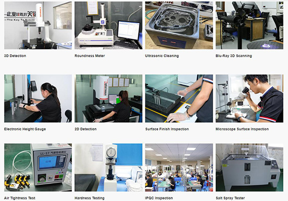
A reliable CNC milling process should not wait until the very end to discover whether a part is out of tolerance.
In-process inspection is used to check critical dimensions at selected machining stages so that errors can be identified before they continue into later operations, surface finishing, or batch production.
For the 6061-T6 aluminum housing in this example, inspection points are placed after major material removal, repositioning, precision hole machining, and finish machining.
If a critical feature is wrong after the first or second setup, continuing to machine the remaining features only adds more time and cost to a part that may already require rework or replacement.
In-process inspection helps control risks such as:
This is especially important for parts that require several machining operations or multiple re-clamping steps.
The goal is not to inspect every dimension after every toolpath. The goal is to identify the dimensions that provide the best indication of whether the process remains stable.
After rough machining, the part may have released residual stress or changed shape.
At this stage, engineers may check:
These measurements help determine whether the planned semi-finishing and finishing allowances are still sufficient.
For the aluminum housing, if the part has warped more than expected after the main pocket is roughed, the process can be adjusted before the final mating surface or thin walls are completed.
When the part is flipped into a second or third setup, inspection should confirm that the new datum relationship has been recovered correctly.
Useful checks may include:
If these dimensions are already drifting, it may indicate:
Catching the problem at this stage prevents it from affecting every feature machined afterward.
After machining locating holes, bores, or threaded features, selected inspection methods may include:
The inspection method should match the function of the feature.
For example, a precision dowel hole may require both diameter and positional verification.
A threaded hole may require checking:
A clearance hole may only require diameter and location verification.
In-process inspection is also useful for identifying gradual process drift caused by tool wear.
For example, if a finished wall dimension changes slightly from one part to the next, the cause may be:
In batch production, measuring selected critical dimensions at defined intervals allows the team to identify these trends before they create a larger group of nonconforming parts.
This is more effective than waiting until final inspection to discover that several parts have already moved outside tolerance.
Different dimensions require different inspection equipment.
Common tools include:
Calipers
Useful for general dimensions where very high precision is not required.
Micrometers
Used for more accurate thickness, diameter, or external dimension measurement.
Height Gauges
Useful for dimensions referenced from a controlled surface.
Pin Gauges
Commonly used to verify hole diameters and fits.
Thread Gauges
Used to confirm threaded features.
Bore Gauges
Useful for precision internal diameters.
CMM
Used for more complex dimensional and geometric relationships, including:
The inspection method should be selected based on the drawing requirement rather than using the same tool for every feature.
For thin-wall or deformation-sensitive parts, some dimensions should also be checked after the part is released from the fixture.
A thin housing can appear correct while clamped because the fixture is temporarily holding it in position.
After release, the geometry may change.
For this reason, important dimensions such as:
may need to be verified without excessive external force acting on the part.
This provides a more realistic indication of how the component will behave during actual assembly.
Inspection should not be added randomly after machining begins.
During the earlier process-planning stage, engineers should define:
For the aluminum housing, a simplified inspection plan might include:
After Roughing
After Setup 2
After Critical Hole Machining
After Finish Machining
This creates checkpoints throughout the CNC milling workflow instead of relying on one inspection at the end.
For a new custom part, the first completed part should normally receive more detailed inspection before the process is released for batch production.
The purpose of first article inspection is to verify that the complete manufacturing route is working as intended, including:
If a problem is found on the first article, the process can be corrected before the same issue is repeated across the full production quantity.
For repeat orders, the validated process can then be standardized to improve consistency between batches.
For the housing in this guide, in-process inspection may follow this sequence:
This approach prevents quality control from becoming only a final sorting activity.
Tip: The best inspection point is usually placed immediately after a process that can create an irreversible error. If a critical dimension can still be corrected while machining allowance remains, measure it before that allowance is removed.
After finish machining and in-process inspection, the next step is to remove burrs, sharp edges, chips, and machining residue before the part moves to surface finishing or final inspection.
Deburring may look like a minor operation, but poor burr control can cause real assembly problems. A part can meet dimensional requirements and still fail in use because a hidden burr prevents a screw, pin, seal, connector, or mating component from fitting correctly.
For the 6061-T6 aluminum housing in this example, special attention should be given to hole entrances, pocket edges, threaded features, intersecting holes, and cosmetic surfaces before black anodizing.
Burrs are most likely to appear around:
The amount of burr depends on:
Aluminum is relatively easy to machine, but it can still form rolled or feather-like burrs around thin edges and drilled features.
A small burr may be difficult to see, but it can affect:
For example, if a burr remains around a precision locating hole, the mating pin may not seat fully even if the hole diameter itself is correct.
A burr on a flat mounting surface can also create a false high point and affect assembly alignment.
This is why burr control should be treated as part of functional quality, not only cosmetic cleanup.
Cross holes and intersecting passages are more difficult to deburr because the burr may form inside the part rather than on an exposed edge.
These hidden burrs can be especially problematic in parts used for:
Depending on the geometry, burr removal may require:
Where possible, it is better to control burr formation during machining rather than rely entirely on manual cleanup afterward.
Many CNC drawings specify edge requirements such as:
These requirements should be interpreted according to the part function.
For the aluminum housing, a small chamfer may be added to:
This can improve:
However, excessive edge breaking can also change functional geometry.
For example, too large a chamfer around a sealing surface or precision locating feature may reduce usable contact area.
Manual deburring can create scratches if the part is handled carelessly.
For cosmetic housings, surfaces that will later be anodized should be protected from:
Deep scratches are not always hidden by anodizing. In many cases, anodizing can make inconsistent surface conditions more visible rather than less visible.
This is why deburring tools and methods should be selected according to the surface requirement.
After machining, chips may remain inside:
These chips should be removed before inspection and surface finishing.
If chips remain inside threaded holes, they can interfere with:
Typical cleaning methods may include:
The cleaning method should avoid damaging the part or contaminating surfaces that will receive finishing.
Before anodizing, plating, coating, or polishing, the part should be free from:
Surface contamination can interfere with later finishing and may contribute to:
Final cleaning requirements depend on the finishing process, but the machining department should deliver a clean and stable part to the finishing stage.
Thread entrances often require a small chamfer or burr removal.
However, the process should not damage the first thread or reduce usable engagement length.
For the M3 threaded holes in the example housing, the team may:
This is particularly important before anodizing, because thread masking or coating effects may introduce additional fit considerations later.
For the housing in this guide, the deburring and cleaning process may include:
At this point, the CNC machining itself is essentially complete, but the part is not yet finished. The next stage must ensure that the required surface treatment does not compromise dimensions, threads, mating surfaces, or cosmetic quality.
Tip: Deburring should be defined during process planning, not left as an uncontrolled manual operation at the end. Features that are difficult to access after machining are often better handled with programmed chamfers or dedicated deburring operations while the part is still accurately located in the machine.
After deburring and cleaning, the part is ready to move from machining into surface finishing. At this stage, the main challenge is no longer only dimensional accuracy. The machining team must make sure the finishing process does not create new problems with fit, threads, coating thickness, cosmetic appearance, or critical mating surfaces.
For the 6061-T6 aluminum housing in this example, the specified finish is black anodizing. That means the finishing requirements should be reviewed again before the part leaves the machining department.
Surface finishing can change the condition of the machined part.
Depending on the process, it may affect:
For anodized aluminum parts, the oxide layer grows partly into the material and partly outward from the original surface.
This means features with tight fits may need to be evaluated before machining is finalized.
Examples include:
If these features are ignored until after anodizing, the finished part may pass machining inspection but fail during assembly.
Not every surface necessarily needs the same finish.
Depending on the drawing and assembly requirements, some areas may need to remain uncoated.
Typical masking locations include:
For the aluminum housing, the engineer should confirm whether the M3 threads are:
The same review applies to precision locating holes and mating surfaces.
Masking requirements should be clearly communicated to the finishing supplier rather than assumed.
For ordinary cosmetic dimensions, anodizing thickness may have little practical impact.
For tight-fit features, however, even a small surface build-up can matter.
For example, if a precision bore is machined exactly to the final assembly limit before anodizing, the coating may reduce the usable diameter.
This can affect:
The machining team should therefore identify which dimensions are:
This is especially important when the drawing specifies tight tolerances together with anodizing, plating, or coating.
The surface condition before anodizing directly influences the final appearance.
Black anodizing does not automatically hide:
For visible housings, these defects may remain visible after finishing or become more noticeable because of differences in texture and light reflection.
Before the housing is released for anodizing, the cosmetic surfaces should therefore be checked for:
If the part will receive bead blasting before anodizing, the machining team should also identify which surfaces must remain dimensionally controlled and whether blasting could affect sharp edges or cosmetic transitions.
The final anodized appearance depends not only on the anodizing tank.
It can also be influenced by the condition of the metal before anodizing.
Possible preparation methods may include:
For example, a bead-blasted black anodized housing will usually have a different appearance from a directly machined and anodized housing.
The desired cosmetic result should therefore be defined before finishing.
Important factors may include:
For cosmetic aluminum parts, color consistency can become a major customer concern.
Anodized color may be influenced by factors such as:
For repeat production, using the same material grade and maintaining a controlled finishing process can help reduce visible variation.
If multiple housings will be assembled into the same product, color matching should be discussed before mass production rather than evaluated only after the full batch has been completed.
Before the part is transferred for finishing, the machining team should communicate the required process clearly.
For the aluminum housing, the finishing instruction may include:
If a color sample, approved reference part, or customer-defined finish standard exists, it should also be used where appropriate.
This reduces the risk of a technically anodized part being rejected because the appearance or masking does not match the customer's requirement.
A pre-finishing inspection helps ensure that machining defects are not passed into the finishing stage.
The team may confirm:
This is important because once surface finishing is complete, correcting a machining defect may require:
The cost of correction usually increases significantly after finishing.
For the housing in this guide, the preparation process before black anodizing may include:
At this stage, the objective is to make sure the surface finish improves the part without changing its functional performance.
Tip: Do not treat anodizing, plating, or coating as a separate process added after machining. If a finished dimension, thread, bore, sealing surface, or cosmetic requirement is important to your assembly, it should be included in the machining and inspection plan from the beginning.
After surface finishing is complete, the part should go through final inspection before it is approved for packaging and shipment.
This stage verifies that the finished component still meets the drawing requirements after all machining, deburring, anodizing, handling, and secondary operations are complete.
For the 6061-T6 aluminum housing in this example, final inspection should confirm not only dimensions, but also flatness, hole position, thread quality, surface condition, anodizing appearance, and assembly-related features.
A part can pass machining inspection before anodizing and still change afterward.
Surface finishing may affect:
This is why some critical features should be checked both:
before finishing and after finishing.
The pre-finish inspection confirms that machining is correct.
The post-finish inspection confirms that the final delivered part still meets the customer’s functional requirements.
Final dimensional inspection should focus on the features that affect assembly and function.
For the aluminum housing, this may include:
Not every dimension needs the same inspection method.
Critical dimensions should be measured with equipment suitable for the specified tolerance.
If the drawing includes geometric tolerances, final inspection should verify them from the specified datum system.
Typical GD&T requirements may include:
For example, the housing may require the locating holes to maintain position relative to the main mating surface.
In that case, checking the hole diameter alone is not enough.
The relationship between the hole and the datum must also be verified.
A coordinate measuring machine (CMM) is useful when a part includes multiple critical dimensions or complex GD&T relationships.
CMM inspection can help verify:
For the example housing, a CMM may be used to confirm that the mounting and locating features remain correct after machining and anodizing.
This is especially useful for parts that must assemble with another precision component.
Threads should be verified again when surface finishing may affect fit.
For the M3 holes in the aluminum housing, the inspection may include:
This helps prevent a common situation where the thread passed inspection before anodizing but becomes too tight afterward.
If the drawing specifies a surface roughness value on a functional area, the final inspection may include roughness measurement.
This is particularly important for:
Cosmetic surfaces are often judged differently.
They may require visual inspection rather than Ra measurement alone.
For the black anodized housing, the final inspection should also review:
Cosmetic inspection should be performed under controlled conditions when appearance is important.
For example, the customer may define:
Without a consistent inspection standard, one person may accept a surface that another person rejects.
The final part should also be evaluated from the perspective of assembly.
Depending on the application, this may include checking:
For higher-risk parts, an assembly test or functional gauge may be more meaningful than checking isolated dimensions only.
For batch production, final inspection should also confirm that the finished parts can be traced back to the correct production lot.
Depending on project requirements, traceability may include:
This becomes especially important when several revisions of the same part are produced over time.
Shipping the correct revision is just as important as machining the dimensions correctly.
For customer projects that require documentation, the final inspection package may include:
The exact documentation should match the project requirement.
For prototype parts, a simplified inspection report may be sufficient.
For repeat production or more controlled industries, more complete traceability may be required.
For the housing in this guide, final inspection may follow this sequence:
The purpose of final inspection is not simply to sort good parts from bad parts.
A strong quality process uses final inspection to confirm that the entire CNC milling workflow—from drawing review to finishing—has produced the part exactly as intended.
Tip: Final inspection should follow the same datum logic and functional requirements defined on the drawing. Measuring a feature accurately from the wrong reference can still produce an inspection result that does not reflect how the part will behave in assembly.
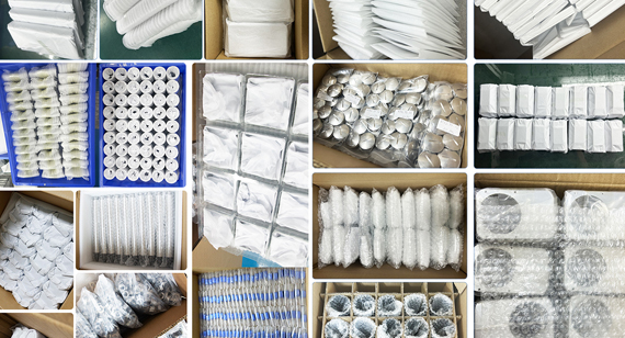
Once final inspection is complete, the part still has one more important stage before it reaches the customer: packaging and shipment protection.
A CNC machined part can meet every dimensional requirement and still become unusable if it is scratched, dented, contaminated, or mixed with the wrong batch during transportation. This is especially important for finished aluminum housings with cosmetic anodized surfaces.
For the 6061-T6 black anodized housing in this example, packaging should protect both function and appearance.
Anodized aluminum surfaces can be damaged when finished parts rub against each other during handling or shipment.
Possible defects include:
For visible housings, parts should be separated rather than packed loosely together.
Depending on size, geometry, and quantity, suitable protection may include:
The goal is to prevent direct metal-to-metal contact.
Packaging should also protect features that affect assembly.
These may include:
For example, if the housing has a flat sealing face, that surface should not be allowed to contact hard packaging materials directly.
A small dent on a cosmetic edge may be unacceptable visually, while a dent on a sealing or locating surface may make the part functionally unusable.
Before packaging, the parts should be checked for:
This is particularly important for parts used in:
The required cleanliness level depends on the customer’s application, but finished parts should not arrive contaminated from manufacturing or packaging.
Thin-wall housings can be damaged not only by impact but also by excessive pressure from packaging.
If heavy parts are stacked directly on top of thin aluminum components, the load may cause:
Packaging should support the part at stronger structural areas and avoid placing pressure on flexible walls.
For more delicate geometries, custom trays or shaped foam may be used to hold the component securely without forcing it out of shape.
Packaging is also part of production traceability.
Each shipment should clearly identify information such as:
For projects with multiple similar parts, clear labeling reduces the risk of:
This becomes increasingly important in repeat production.
If the customer requires quality documentation, the records should correspond to the actual parts being shipped.
Depending on the project, the shipment package may include or reference:
This ensures that the customer can trace the delivered parts back to the correct manufacturing and inspection records.
For international shipments, packaging may need to withstand:
This means packaging should be selected according to the actual shipping route, not just the condition inside the factory.
For heavier or higher-value CNC parts, stronger outer cartons, reinforced packaging, or custom protective solutions may be required.
For the black anodized housing in this guide, the packaging process may include:
At this point, the CNC milling process is complete—from drawing review and DFM through machining, finishing, inspection, and final delivery protection.
Tip: Packaging should be treated as the final manufacturing control step. If a part arrives scratched, dented, mixed with the wrong revision, or damaged at a critical mating surface, the customer experiences it as a manufacturing failure regardless of how accurately it was machined.
To make the entire CNC milling process easier to understand, the following example shows how a typical 6061-T6 aluminum housing moves from raw material to a finished, black-anodized custom part.
This is not intended to represent one specific customer project. It is a practical example of how process planning, fixturing, machining sequence, inspection, and surface finishing work together on a common precision CNC milled housing.
The part begins as a 6061-T6 aluminum block and includes several features commonly found in custom housings:
Although none of these features is unusual by itself, combining them in one part creates several manufacturing challenges.
The main risks are not simply whether the cutter can reach the geometry. The factory also needs to control:
The process starts with the 2D drawing and 3D model.
The engineer identifies the features that directly affect assembly, such as:
The first objective is to understand which features must receive the highest process-control priority.
For example, if the two locating holes control the housing position in the final assembly, their relationship to the mating surface is more important than a non-functional external edge.
The housing is then reviewed for manufacturing risks.
The engineer may identify that:
If a design change can simplify machining without affecting function, DFM feedback can be provided before production begins.
If the design cannot change, the manufacturing process must be adjusted to control the risk.
The material grade and condition are confirmed before machining.
The raw aluminum stock is cut oversize so enough material remains for:
The blank is then cleaned and prepared for the first machining setup.
For projects requiring traceability, the material batch and relevant documentation can be linked to the production lot.
Before cutting the housing geometry, the engineer determines the datum strategy.
A practical route may establish a flat machined surface early and reuse that surface as a reference in later setups.
The machining sequence may be planned as:
Setup 1: Establish datum and rough the main pocket
Setup 2: Flip the part and machine the opposite side
Setup 3: Machine side features if required
Later operations: Finish critical surfaces, holes, and threads after the part becomes more stable
This reduces unnecessary tolerance accumulation between setups.
The raw blank may initially be held in a vise or suitable fixture.
After the main geometry is created, the housing becomes less rigid, so later setups may require:
The clamping points should avoid directly loading the thin-wall sections.
This is important because a thin housing can be forced into shape while clamped and then spring back after release.
The CAM program is then created around the approved process plan.
A larger end mill can remove most of the material from the main pocket, while smaller tools are reserved for tighter corners and detailed geometry.
The program separates:
Before machining begins, the toolpaths are simulated to check tool reach, fixture clearance, collisions, and remaining material.
The blank is loaded into the machine and the first reference surface is face milled.
This gives the part a controlled datum that can be used for later dimensions and repositioning.
Before the main roughing operation starts, the operator confirms:
Most of the material inside the housing is now removed.
However, the walls and critical surfaces are not immediately cut to final size.
Controlled stock is left for later operations.
This gives the part room to move after major material removal while still leaving enough material for correction during semi-finishing and finishing.
The thin-wall sections therefore remain slightly stronger during the highest-load machining stage.
After roughing, the housing may be released, re-clamped, and checked for movement.
If the large pocket has caused:
the process can still be adjusted because finishing stock remains.
The part may then be semi-finished to bring the geometry closer to final dimensions without removing the last correction allowance.
The part is repositioned using the machined datum.
The opposite side is then machined to control:
The locating surfaces must be clean and stable so chips or burrs do not create a false setup position.
At this stage, the part is closer to its final structure and therefore more sensitive to clamping force.
Once the housing body is stable, the locating holes and threaded features can be completed.
For example:
Precision locating holes are machined from the controlled datum so their position reflects the final assembly relationship.
The threads are also checked for usable depth and burr-free entrances.
The remaining stock is now removed from:
Finishing passes use lighter cutting forces to improve:
Critical dimensions are measured before the part is removed from the setup.
For deformation-sensitive features, selected measurements may also be repeated after unclamping.
Inspection points are used throughout the process rather than only at the end.
For the housing, these may include:
This helps identify problems while corrective machining is still possible.
Once CNC machining is complete, all edges, holes, threads, and internal areas are checked for burrs.
Special attention is given to:
The part is then cleaned to remove chips, coolant, oil, and other contamination before anodizing.
Before surface finishing, the team confirms:
The cosmetic surfaces are also checked for scratches or handling marks because anodizing will not necessarily hide them.
After black anodizing, the housing returns for final inspection.
The team checks:
Critical dimensions may be checked with CMM or other suitable inspection equipment depending on the drawing requirements.
Finally, the finished housing is protected so the anodized surface is not damaged during shipment.
The packaging may separate each part and protect:
The shipment is labeled with the correct part number, revision, quantity, and batch information.
The complete route can be summarized as:
2D Drawing + 3D Model
→ DFM Review
→ 6061-T6 Material Verification
→ Blank Preparation
→ Datum Planning
→ Fixture Design
→ CAM Programming
→ Setup 1
→ Rough Machining
→ Stress / Deformation Check
→ Semi-Finishing
→ Setup 2
→ Critical Holes and Threads
→ Finish Machining
→ In-Process Inspection
→ Deburring and Cleaning
→ Black Anodizing
→ Final Inspection
→ Protective Packaging
→ Shipment
If this same housing is machined without a well-planned workflow, possible problems include:
This is why the quality of a CNC milled part depends on much more than machine accuracy alone.
The final result is created by the complete combination of drawing review, datum planning, fixture control, machining sequence, toolpath strategy, inspection, surface finishing, and delivery protection.
Tip: When comparing CNC machining suppliers, do not only ask what tolerance their machines can achieve. Ask how they plan the datum, fixtures, rough-to-finish sequence, in-process inspection, and finishing control for your specific part. That process is often what determines whether the same tolerance can be repeated across the full production batch.
The total time required for a CNC milling process depends on much more than the machine cycle itself.
For a custom part, the complete lead time can include:
This means two parts with similar overall dimensions can still require very different production times.
The more complex the geometry, the longer the machining process usually takes.
Features that can increase lead time include:
For example, a simple aluminum plate with drilled holes may be completed quickly.
The 6061-T6 aluminum housing used in this guide requires more time because it includes a large pocket, thin walls, locating holes, threads, multiple setups, finishing, and anodizing.
The difference is not only cutting time. More complex parts also require additional programming, fixture planning, inspection, and process verification.
Every additional setup adds time.
A part that can be completed from one orientation may require:
A part requiring three or four orientations may need additional:
This is one reason 4-axis or 5-axis machining can sometimes reduce total lead time for complex parts, even if the hourly machine rate is higher.
Fewer setups can also reduce tolerance-transfer risk.
Different materials require different cutting conditions.
Aluminum such as 6061-T6 can generally be machined faster than harder or more difficult materials such as:
Harder or work-hardening materials may require:
As a result, the same geometry can have very different cycle times depending on the specified material.
Tight tolerance does not only affect the final finishing pass.
It can also increase time required for:
For example, a non-critical external dimension with ±0.10 mm tolerance is usually easier to produce than a flat mating surface or locating-hole pattern controlled within much tighter limits.
If tight tolerances are applied unnecessarily across the whole drawing, both machining time and inspection time can increase.
A CNC part may be complete from a machining perspective but still require secondary finishing.
Common surface treatments include:
For the example housing, black anodizing adds additional steps after machining:
Cleaning → Pretreatment → Anodizing → Coloring → Sealing → Final Inspection
If the part also requires bead blasting before anodizing, masking of threads, or tighter color consistency, additional process time may be needed.
Surface finishing should therefore be included when evaluating the total delivery schedule.
A simple prototype may only require inspection of key dimensions.
A precision production part may require:
These quality requirements add time, but they also reduce the risk of nonconforming parts reaching assembly.
For critical components, inspection time should be planned as part of manufacturing rather than treated as an optional final step.
The first prototype usually takes longer per part because the manufacturing process is being established.
The factory may need to:
Once the process is validated, repeat production can become more efficient because the:
have already been confirmed.
For batch production, the main focus shifts from process development to repeatability and cycle-time control.
For custom CNC projects, lead time depends on the actual drawing and finishing requirements, but VMT commonly supports:
These time ranges are not fixed promises for every part. A more accurate schedule can only be confirmed after reviewing your drawing, material, tolerance, quantity, and surface-finishing requirements.
For the housing in this guide, total production time may include:
The CNC cutting time is therefore only one part of the total lead time.
A supplier that quotes only machine hours without considering engineering, inspection, finishing, and handling may give you an unrealistic delivery estimate.
Tip: If your project has a fixed launch or assembly date, tell your CNC supplier before production starts. Material availability, fixture complexity, surface finishing, inspection documentation, and shipping should be planned backward from your required delivery date—not added after machining is already complete.
The cost of a CNC milling process is not determined by machine time alone.
For a custom part, the final price is influenced by the complete manufacturing route, including drawing complexity, material, setup count, fixture requirements, machining time, tolerance, inspection, surface finishing, and production quantity.
This is why two parts of similar size can have very different CNC milling costs.
For the 6061-T6 aluminum housing used in this guide, the main cost drivers come from how difficult the part is to manufacture reliably—not simply from how much aluminum is removed.
More complex geometry usually requires more:
Features that commonly increase machining cost include:
For example, a simple rectangular aluminum plate may only require basic facing, drilling, and contour milling.
The aluminum housing in this guide requires:
That makes its manufacturing route more complex and therefore more expensive.
Every setup adds labor and process risk.
Each time the part is repositioned, the factory may need to:
If a part requires three or four separate orientations, the setup cost can become significant.
Reducing unnecessary setups can therefore lower cost.
This is one reason a 4-axis or 5-axis machine may sometimes be more economical for complex parts, even when its hourly rate is higher.
If the advanced machine reduces several setups into one, the total manufacturing cost may decrease.
Tighter tolerances require more process control.
A tolerance such as ±0.10 mm may be relatively easy on a non-critical feature.
A requirement such as ±0.01 mm may require:
The cost increases further when very tight tolerances are applied to many dimensions.
This is why tolerances should match actual functional needs.
For the example housing, the locating holes and mating surfaces may justify tighter control, while some cosmetic outer dimensions may not.
Thin-wall parts often require more machining time because cutting forces and clamping must be carefully controlled.
The process may include:
These additional operations increase cycle time, but they also reduce the risk of:
A cheaper process that removes material too aggressively may reduce machine time initially but increase scrap and rework later.
Internal corner radius has a direct effect on cutter size.
A very small radius may require:
For example, if a deep pocket can accept an R3 internal corner, the factory may use a larger and more rigid cutter.
If the same pocket requires R0.5, a much smaller tool may be needed for the final corner machining.
If the small radius is not functionally necessary, increasing it can be a simple way to reduce cost.
Deep features often require long-reach tools.
Longer tools are less rigid and may require:
This increases machining time.
Deep pockets can also make chip evacuation more difficult, which can further reduce cutting efficiency.
Where the design allows, reducing unnecessary depth or improving tool access can lower machining cost.
Material affects both raw-material cost and machining time.
6061-T6 aluminum is generally easier to machine than:
Harder materials may require:
Material choice should therefore consider both part performance and manufacturability.
Choosing a more expensive alloy than the application requires can increase cost without improving the final product.
A large number of holes or threads can add substantial cycle time.
Each feature may require:
Small blind threads can be especially time-consuming if they require controlled depth and careful chip evacuation.
For the housing example, each M3 threaded hole adds more than just a few seconds of cutting. It also adds drilling, tapping, cleaning, and inspection requirements.
A standard machined surface is usually less expensive than a highly controlled cosmetic or functional finish.
Requirements such as:
add extra processing steps.
For the black anodized housing, cost may include:
Cosmetic requirements can also increase handling cost because scratches and dents must be prevented throughout the production process.
Inspection also contributes to CNC milling cost.
A simple part may only require basic dimensional checks.
A precision part may require:
The more critical the part, the more quality-control time may be required.
Inspection should not be viewed as wasted cost. For critical components, it reduces the risk of assembly failure, rejected batches, and expensive downstream problems.
Quantity affects unit cost significantly.
For a prototype, the cost of:
is spread across only one or a few parts.
For larger production quantities, these initial engineering costs are distributed across more pieces.
The per-part cost can therefore decrease as quantity increases.
However, large production runs may require additional investment in:
These investments may increase initial cost but reduce the unit cost and improve repeatability over the full batch.
DFM review is one of the most effective ways to reduce cost before production begins.
Common opportunities include:
The goal is not to simplify the part at the expense of function.
The goal is to remove manufacturing difficulty that does not provide real value to the final product.
For the housing in this guide, the main cost drivers may include:
A DFM review may reduce cost by:
The lowest quotation is therefore not always the lowest final manufacturing cost.
If a low-cost process increases deformation, rework, surface defects, or assembly failure, the total project cost can be much higher.
Tip: When comparing CNC milling quotations, ask what is included. Material, fixtures, inspection, surface finishing, quality documentation, and packaging can make two quotations look very different even when the machine cycle is similar.
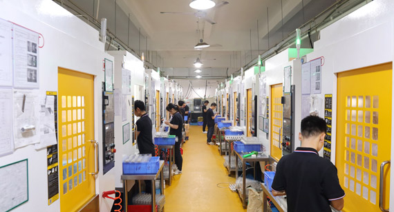
A stable CNC milling process depends on more than machine accuracy. The final result is created by how the drawing, datum, fixture, toolpath, machining sequence, inspection, surface finishing, and packaging are controlled as one connected workflow.
At VMT, the goal is not simply to machine the geometry shown in your CAD model. The process is built around the features that affect your assembly, function, appearance, and repeat production.
Before machining starts, the engineering team reviews your:
The purpose is to identify manufacturing risks before they become machining problems.
For example, the review may identify:
When necessary, VMT provides DFM feedback so you can decide whether to optimize the design or keep the drawing unchanged and control the risk through the manufacturing process.
Critical dimensions should not be machined independently without considering how they relate to the rest of the part.
VMT engineers plan:
before releasing the program to production.
For the aluminum housing example, the process would prioritize the relationship between the:
Where practical, closely related features are machined from the same datum or in the same setup to reduce tolerance accumulation.
Workholding is selected according to the geometry and production stage.
Depending on your part, VMT may use:
For thin-wall parts, clamping force and support locations are controlled so the fixture does not distort the part before machining begins.
When the geometry changes after roughing, the workholding strategy may also change for later setups because the part is no longer as rigid as the original blank.
For parts with high material removal, thin walls, or tight geometric requirements, VMT does not rely on one aggressive machining stage.
The process may be separated into:
Rough Machining → Stabilization → Semi-Finishing → Finish Machining
This makes it possible to identify part movement while machining stock still remains.
For deformation-sensitive parts, the process may also include:
This is especially useful for housings, plates, frames, and other parts where removing a large percentage of the original material can affect final geometry.
CAM programming is created around the actual machining risk.
The engineering team considers:
For thin-wall or precision features, the toolpath can be adjusted to reduce cutting force and deflection.
For deep pockets, larger rigid cutters may remove most of the material first, while smaller tools are used only where necessary.
Programs are also simulated before machining to reduce the risk of:
Quality control is integrated into the CNC milling workflow.
Depending on the part, VMT may inspect critical dimensions:
Inspection equipment may include:
Critical dimensions can be checked during production so that process drift is identified before it affects an entire batch.
For suitable projects, VMT performs 100% inspection of critical dimensions and can provide dimensional or CMM inspection reports according to customer requirements.
For a new custom part, the first article is used to confirm whether the complete manufacturing route is stable.
The first article can validate:
If a problem is found, the process can be corrected before larger-volume production begins.
Once the prototype and first article are approved, the validated parameters can be standardized for pilot and repeat production.
This helps improve batch-to-batch consistency.
Surface finishing is not treated as an unrelated final step.
For anodizing, plating, polishing, PVD, passivation, or other finishes, VMT reviews how the process may affect:
This is important because a dimension that is correct before finishing may not remain correct afterward if coating buildup or masking requirements are ignored.
By considering the finish during machining and inspection planning, the final delivered part is controlled according to its actual assembly condition.
After all machining and finishing operations are complete, the finished part is checked against the latest drawing and revision.
Depending on the project, final inspection may include:
After approval, the parts are packaged according to their geometry and surface requirements.
For cosmetic or precision components, VMT may use:
to reduce scratches, dents, and part-to-part contact during transportation.
The goal is to make sure the condition that passes final inspection is the same condition you receive.
VMT supports the complete custom CNC milling workflow from prototype development to repeat production.
The same process-control logic can be carried through:
DFM Review → Prototype → First Article Validation → Pilot Batch → Mass Production → Final Inspection → Delivery
This is especially important when your project requires not only one acceptable prototype, but stable dimensions and appearance across multiple production batches.
Tip: When evaluating a CNC milling supplier, do not only ask for machine tolerance or hourly rate. Ask how the supplier controls datum transfer, fixtures, deformation, in-process inspection, surface finishing, and first article validation. These controls are often what determine whether the same result can be reproduced consistently.
A reliable CNC milling process is not just about cutting a part to shape. The final result depends on how well the entire workflow is controlled—from drawing review and DFM through datum planning, fixture design, roughing, finishing, inspection, surface treatment, and final packaging.
If any one of these stages is poorly planned, problems can appear later as:
This is why the best time to control machining risk is before production starts.
At VMT, you can send your 2D drawing and 3D CAD model for engineering review before machining. Our team can evaluate your:
Where needed, we can provide DFM feedback to help identify features that may increase machining difficulty, cost, deformation, or inspection risk.
For new projects, VMT supports the complete workflow from:
DFM Review → Prototype → First Article Validation → Pilot Batch → Mass Production → Final Inspection → Delivery
Whether you need a single prototype or repeat production, the goal is the same: build a machining process that produces parts that are not only dimensionally correct, but also stable in assembly and consistent across batches.
Upload your latest:
VMT can review your project and provide a quotation together with manufacturing feedback based on the actual part geometry and production requirements.
Send your drawings, requirements, and target quantity. VMT will review your project and provide a machining solution and quote.
All information and uploaded files are secure and confidential.
1 Tell us what you need
2 Get solution & quote
3 Approve production
Email: inquiry@vimetal.com.cn
You should provide as much manufacturing information as possible before production begins.
Ideally, send:
The 3D model defines the geometry, while the 2D drawing communicates critical manufacturing and inspection requirements.
If some information is missing, the CNC supplier may need to make assumptions, which increases the risk of quotation differences, machining errors, or assembly problems.
For a new project, it is better to clarify critical requirements before CAM programming and fixture preparation begin.
For many custom CNC milled parts, providing both is the best option.
The 3D model helps the factory understand:
The 2D drawing usually provides information that may not be fully defined in the 3D model, including:
A part can be geometrically correct according to the 3D model but still fail assembly if the functional tolerance or datum requirement is misunderstood.
If you only have a 3D model, machining may still be possible for simpler parts, but critical dimensions and finishing requirements should be confirmed before production.
Rough machining and finish machining have different purposes.
Rough machining removes most of the material efficiently.
Finish machining controls the final dimensions, geometry, and surface quality.
Separating the two stages helps reduce the effect of:
For example, if a large aluminum housing pocket is machined directly to final wall thickness during roughing, the thin walls may move after the part is unclamped.
By leaving machining allowance, the factory can inspect the part after major material removal and then use controlled finishing passes to achieve the final tolerance.
For deformation-sensitive parts, a process such as:
Roughing → Semi-Finishing → Inspection → Finish Machining
is often more stable than cutting directly to final size.
There is no fixed number.
The number of setups depends on:
A simple plate may require only one setup.
A housing may require:
More complex parts may benefit from 4-axis or 5-axis machining to reduce repositioning.
However, fewer setups are not always automatically better.
The real goal is to minimize unnecessary repositioning while maintaining stable workholding and tool access.
For features with tight positional relationships, machining them in the same setup can help reduce tolerance accumulation.
The timing depends on the function of the feature.
Ordinary clearance holes may sometimes be machined earlier in the process.
Precision features such as:
are often machined after the main roughing operations are complete and the part has become more dimensionally stable.
This reduces the risk that later material removal or stress release will change their final position.
Threads should also be planned around:
For anodized parts, the factory should also confirm whether threaded holes need masking or whether coating buildup is acceptable.
Thin-wall deformation is usually controlled through the entire machining process rather than by one single method.
Common controls include:
The fixture is especially important.
If a thin wall is clamped too strongly, it may be forced into position during machining and then spring back after release.
For high-risk parts, the factory may also release and re-clamp the component after roughing to check whether stress redistribution has caused movement before final machining begins.
Inspection should happen at multiple points in the CNC milling process.
Depending on the part, inspection may occur:
After rough machining
To check deformation and remaining stock.
After repositioning
To confirm datum recovery and setup accuracy.
After precision-hole machining
To verify diameter, position, and thread quality.
After finish machining
To confirm final dimensions and geometry.
After surface finishing
To make sure coating, anodizing, or plating has not affected functional features.
For a new part, the first article should normally receive more detailed inspection before the full batch is released.
This helps detect process problems before they are repeated across multiple parts.
Yes, it can.
Processes such as:
may change surface dimensions or fit.
This is especially important for:
For example, anodizing on an aluminum bore can reduce the usable internal diameter.
The machining team should therefore determine before production whether a feature should be:
Surface treatment should be considered during DFM and process planning rather than only after machining is complete.
Yes.
Once a prototype or first article is approved, the process can be standardized for repeat production.
Typical improvements may include:
The goal is not only to reduce cycle time.
For mass production, the process must also maintain:
A process that works for one prototype may therefore need additional fixture and quality-control planning before it is suitable for larger production quantities.


 +86 15099911516




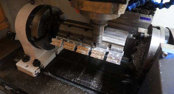
 Read more