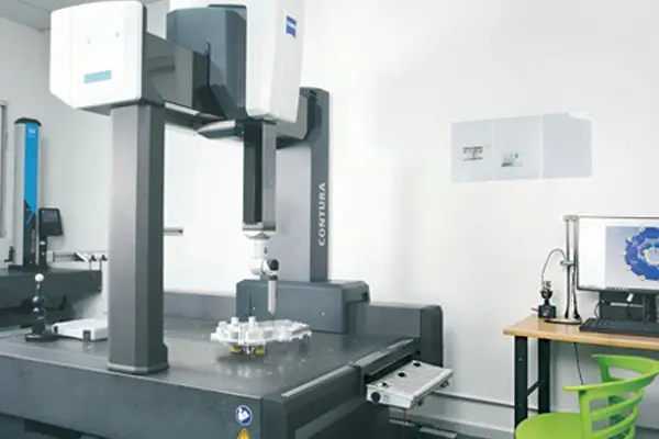
Lens & Sensor Datum Relationships
Datum-based machining keeps lens seats, sensor mounting faces and related bores tied to the same functional reference, reducing assembly tilt and position stack-up.

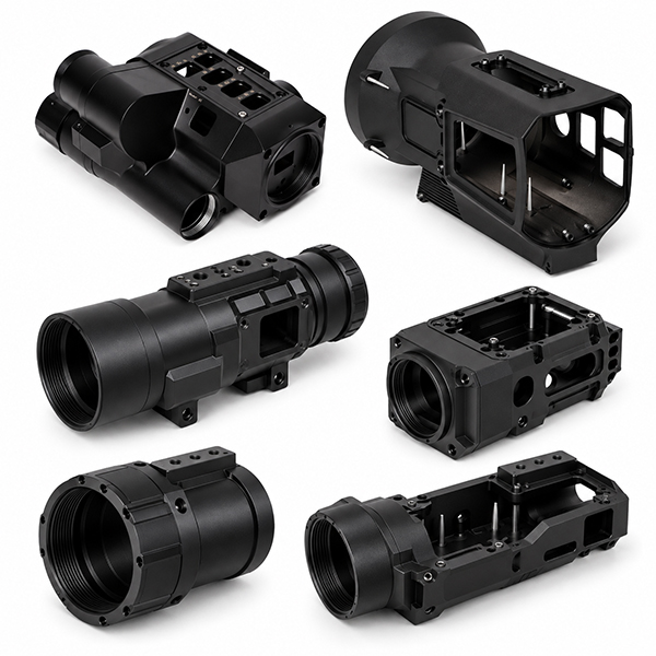
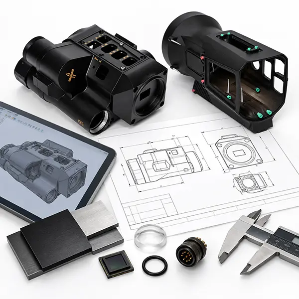
Custom CNC machining for night vision thermal imaging and infrared housings with ±0.005 mm critical-feature capability thin-wall control lens/sensor datum inspection and post-finish fit verification.
 ±0.005 mm Critical Datum Control for Lens, Sensor & Optical Alignment Features
Fixture Optimization + Staged Machining to Minimize Thin-Wall Housing Distortion
Low-Reflectivity Black Finishing + Precision Masking for Optical & Mating Interfaces
Post-Finish Inspection of Critical Bores, Threads & Assembly Fits
Stable Prototype-to-Production Process Control
1 DayPrototyping Machining
2 HoursQuick Quote
0 PcsMinimum Order Qualities
98%Yield


VMT provides build-to-print CNC machining for custom night vision, thermal imaging and infrared imaging housings. Based on your drawings, datums, tolerances, materials and finishing requirements, we combine DFM review, multi-axis machining, fixture optimization, CMM inspection and finishing coordination to support prototypes and repeat production.
For night vision and thermal imaging housings, the difficult part is rarely one isolated tolerance. Optical interfaces, sensor datums, thin walls, sealing features, electronics cavities and finished dimensions must continue to work together after machining and surface treatment.
Datum-based machining keeps lens seats, sensor mounting faces and related bores tied to the same functional reference, reducing assembly tilt and position stack-up.
Multi-axis or indexed machining reduces repeated re-clamping between ports, holes and optical interfaces, helping prevent accumulated positional error across the housing.
Staged stock removal, controlled fixture force and supported finishing reduce the risk that a housing passes while clamped but changes shape after release.
Groove depth, mating-face flatness and adjacent fastener locations are controlled together so the enclosure can assemble consistently to the customer’s sealing design.
PCB pockets, battery cavities, button openings and connector locations are machined against structural datums to reduce interference during final device integration.
Critical bores, threads and mating faces are reviewed for coating allowance, masking and post-finish verification so a qualified machined part remains functional after finishing.
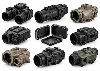
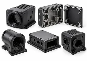
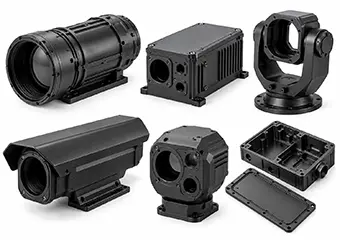
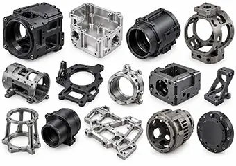
Below are selected examples of CNC-machined prototypes and end-use parts we have manufactured for customers. Each component is produced to customer drawings, and customer-part images are shown with authorization.
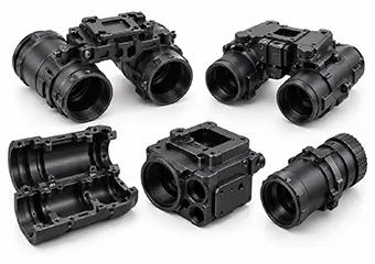
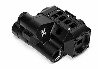
Night vision binocular housings support dual-channel outdoor observation; 5-axis milling controls multi-face optical and electronics interfaces, while datum-based CMM inspection verifies alignment and repeatable assembly.
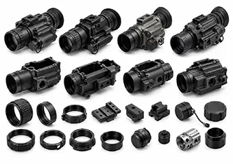
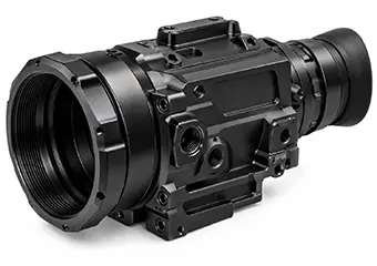
Night vision monocular housings package compact optical and electronic modules; multi-axis milling controls thin walls, lens seats and connector positions, while dimensional inspection confirms clearance and stable final assembly.
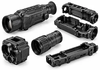
Handheld infrared observation housings protect portable sensing and control modules; 3/4-axis or 5-axis milling controls cavities, interfaces and wall stability, while CMM inspection verifies fit and alignment.
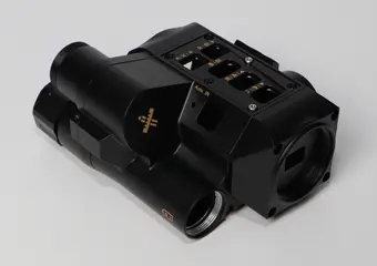
Thermal imaging equipment housings integrate sensors, optics, electronics and sealing features; multi-axis CNC machining controls mating datums and thermal interfaces, while finished-part inspection supports reliable enclosure assembly.
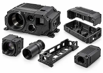
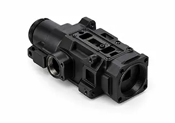
Multi-sensor imaging housings locate optical, infrared and auxiliary modules in one structure; 5-axis machining controls cross-face datums, while CMM verification reduces alignment stack-up during system integration.
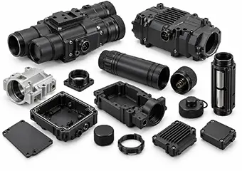
Electronics and battery housings protect boards, cells, connectors and controls; CNC milling controls pockets, threaded features and cover interfaces, while dimensional checks reduce interference and assembly rework.
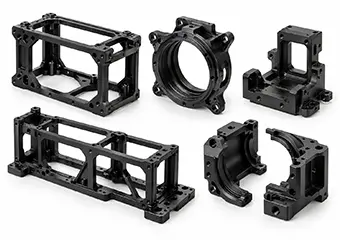
Internal frames and sensor mounts position detectors, boards and optical modules; CNC milling controls flatness, hole location and datum relationships, while CMM inspection supports repeatable internal stack-up.
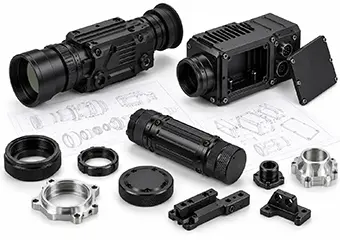
Custom multi-part imaging housings combine bodies, covers, frames and spacers from your drawings; coordinated CNC machining controls mating interfaces, while final inspection verifies fit before prototype or production release.
Before machining, VMT reviews the housing as a manufacturing system. The goal is to identify risks that can affect machining access, distortion, finished fit, inspection and repeat production before those risks become scrap or assembly problems.
VMT’s published milling guide uses 0.8 mm as a metal wall-thickness reference; imaging housings may require more depending on span, material and clamping, helping reduce free-state deformation risk.
Larger internal radii permit stronger, shorter tools and reduce chatter, cycle time and tool-reach problems in deep electronics or sensor cavities.
Keeping deep drilled features within a practical depth-to-diameter range improves chip evacuation and reduces deflection before expensive long-reach tooling is considered.
Suitable bores, seats and mating dimensions can be reviewed for tighter control while noncritical geometry keeps practical tolerances to avoid unnecessary machining and inspection cost.
Primary, secondary and tertiary functional datums are linked to optical, sensor and connector interfaces before setup planning, reducing tolerance accumulation across multiple faces.
Coating-sensitive bores, threads and mating faces are identified for masking, allowance or final reinspection so finishing does not create assembly interference.
The process is selected by geometry and datum relationships. Large housing bodies usually depend on milling, while Swiss and turning processes support small cylindrical, threaded and concentric components within the imaging assembly.
Suitable for prismatic housings, covers, frames and multi-side features where indexed machining can reduce unnecessary 5-axis cost while maintaining controlled datum relationships.
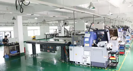
Best for small precision sleeves, threaded pins, bushings, spacers and cylindrical optical-interface parts requiring stable concentric features and repeatable small-diameter production.
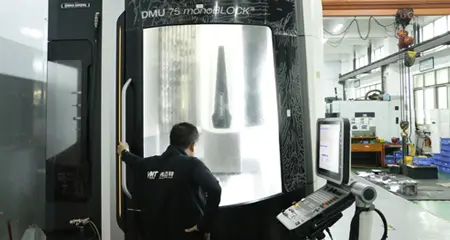
Used for angled optical interfaces, deep multi-face geometry and one-piece housings where reducing setup transfers helps protect positional relationships between critical features.
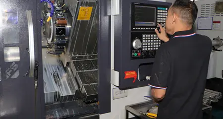
Supports cylindrical housings, threaded sleeves, retaining rings and concentric interfaces that combine turned diameters with milled flats, ports or cross holes.
Support points and clamp force are planned around thin walls, finished surfaces and optical interfaces so the part is not forced into tolerance only while clamped and then distorted after release.
Heavy stock removal is separated from final finishing where needed, allowing geometry to stabilize before critical bores, datum faces and mating features receive their final cuts.
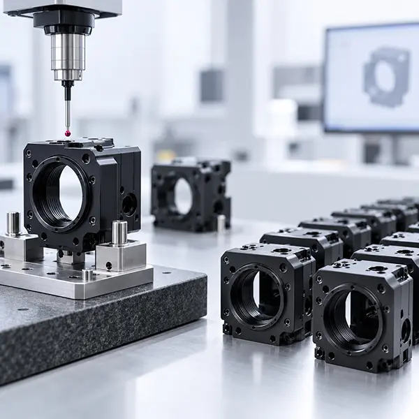
Critical imaging-housing dimensions should be inspected by function, not as isolated numbers. VMT links lens and sensor datums, bores, sealing features, threads and multi-face hole positions to the drawing reference system, then selects CMM, gauges or 100% inspection where required to reduce alignment, fit and post-finishing assembly risks.
Critical seats, bores and sensor-mounting faces are measured from drawing datums with CMM or suitable gauges, helping prevent optical-axis shift and sensor-to-lens assembly tilt caused by independent feature inspection.
Critical IDs, shoulders and seats are checked at the manufacturing stage specified by the drawing; where coating buildup affects fit, masking or post-finish measurement helps avoid loose or interference assembly.
Connector holes, PCB locations and mounting patterns on different faces are verified against common datums, reducing the risk that each hole is individually acceptable but the complete assembly no longer aligns.
Groove geometry and adjacent mating faces are inspected together so gasket compression and enclosure closure follow the customer’s design; VMT does not claim a waterproof rating unless the project includes the required validation.
Thin-wall profiles and critical faces are verified after the part is released from the fixture, helping catch deformation that can remain hidden when clamping force temporarily holds the housing in shape.
Drawing-critical internal and external threads can be gauged after anodizing or coating so buildup does not cause late-stage assembly failure with lens cells, covers, connectors or mating hardware.
For assembly-critical dimensions identified in the drawing or inspection plan, VMT can apply 100% inspection instead of relying only on sampling, helping stop nonconforming features before final shipment.
The right material depends on weight, stiffness, corrosion exposure, thermal stability, finish requirements and the function of the housing or internal structure.
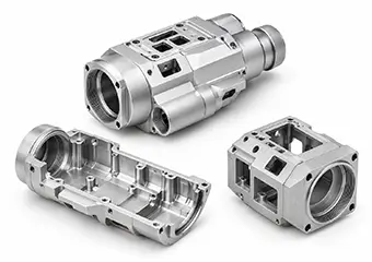
Balanced machinability, corrosion resistance and anodizing response make 6061-T6 a practical choice for lightweight housings, covers and general optomechanical structures.
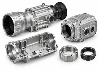
Higher strength and stiffness support thinner or more highly loaded structures where weight must remain low and the design needs greater rigidity than standard aluminum.
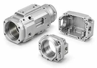
6063 is useful where a clean anodized appearance and moderate structural duty matter, especially for visible housings, rings and enclosure sections requiring cosmetic consistency.
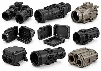
6082 provides good structural strength and corrosion resistance for housings and brackets where European material specifications or stronger structural aluminum are preferred.
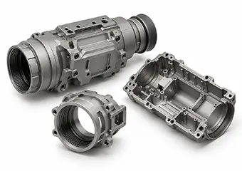
Magnesium is considered for aggressive weight reduction, but machining, corrosion protection and final finishing must be planned together before release.
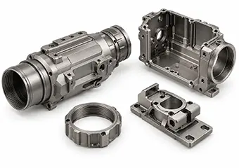
Grade 5 titanium offers high strength-to-weight ratio and corrosion resistance for specialized housings and mounting components where performance justifies higher machining cost.
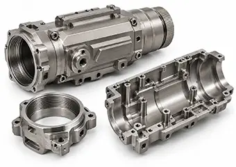
304 and 316 provide rigidity, wear resistance and corrosion protection for inserts, mounts, threaded interfaces and housings where weight is less critical.
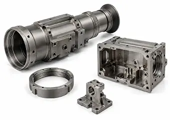
Invar 36 is selected for temperature-sensitive optical and metrology structures where low thermal expansion helps preserve critical mechanical relationships across temperature change.
For precision imaging housings, the finishing plan should protect both appearance and function. Bores, threads, mating faces, sealing regions and electrical-contact areas may require masking, allowance or final inspection.
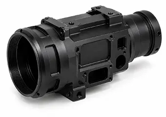
Provides corrosion protection and a controlled dark appearance for aluminum housings while critical fits are reviewed for coating allowance or masking.
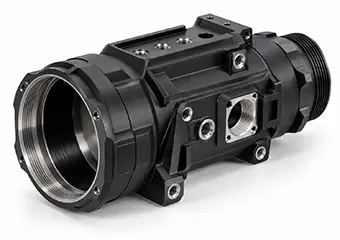
Used where wear resistance and surface hardness are more important, with bores, threads and mating areas protected according to the drawing.
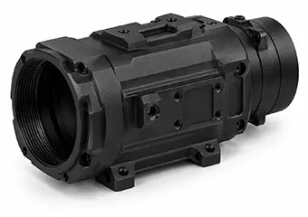
Creates a uniform matte appearance before anodizing and helps maintain consistent cosmetic texture across visible housing surfaces.
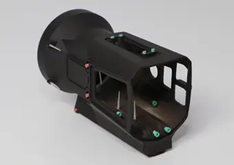
Applied where the drawing requires reduced internal reflection around optical cavities, baffles or sensor-facing internal surfaces.
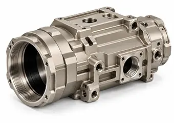
Provides uniform protective coverage on suitable materials while deposit buildup on critical fits is included in the dimensional plan.
Used on suitable wear or appearance surfaces after reviewing material compatibility, coating thickness and any final-fit requirements.
Adds serial numbers, orientation marks and identification without changing the primary machined geometry when marking location is defined early.
Considered for selected protective or appearance requirements after reviewing substrate compatibility, masking zones and dimensional impact on functional interfaces.
A validated prototype only reduces risk when the same datum strategy, fixture, machining sequence, finishing allowance and inspection plan are carried into repeat production. VMT uses first-article approval, in-process monitoring and critical-feature verification to control process drift as quantities increase.
Engineers identify datum, tolerance, wall-thickness, tool-access and finishing risks before CAM release, reducing late drawing changes and avoidable prototype scrap.
The prototype validates the setup, fixture, toolpath and critical-feature measurement plan so production does not restart from an unproven process.
For projects using VMT’s two-hour patrol-inspection plan, dimensions are rechecked during machining so tool wear or process drift can be corrected before affecting an entire batch.
Drawing-defined key features can be fully inspected before shipment, while approved fixture logic, machining sequence and finish controls are retained for repeat orders.
Night vision and thermal imaging housings are used across public safety, industrial inspection, surveillance, UAV, mobility, marine, outdoor and scientific systems where optics, sensors and electronics must remain protected and accurately positioned.
Public safety teams use rugged night-vision and thermal-camera housings for portable observation systems, helping protect sensitive optics and electronics during low-light emergency operations.
Industrial inspection systems use thermal imager, detector and lens housings to maintain sensor alignment and stable assembly during equipment monitoring and predictive-maintenance programs.
Remote surveillance platforms use long-range imaging housings, sensor enclosures and pan-tilt bodies to protect electronics while maintaining repeatable optical positioning in continuous operation.
UAV payloads use lightweight thermal-camera, sensor and lens housings to reduce mass while maintaining rigid mounting, alignment and repeatable integration with aerial systems.
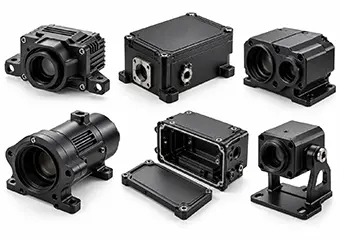
Mobility platforms use night-vision, thermal-sensor and ADAS housings to package optics and electronics compactly while preserving stable mounting datums through vibration and assembly.
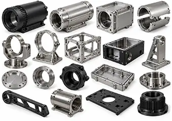
Marine observation systems use corrosion-resistant thermal, navigation-imaging and sensor housings to protect internal components while supporting reliable assembly in moisture-prone operating environments.
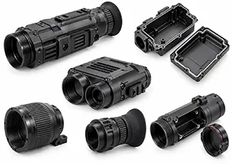
Outdoor observation equipment uses portable thermal, night-observation, lens and battery housings to combine low weight, environmental protection and repeatable field-ready assembly.
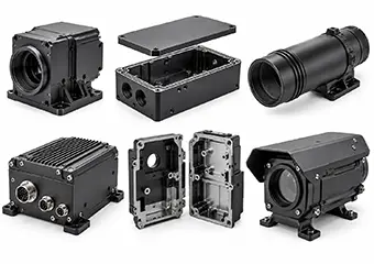
Research and environmental monitoring systems use detector, optical and imaging housings to maintain controlled sensor interfaces and dependable measurements across repeat experimental or field use.
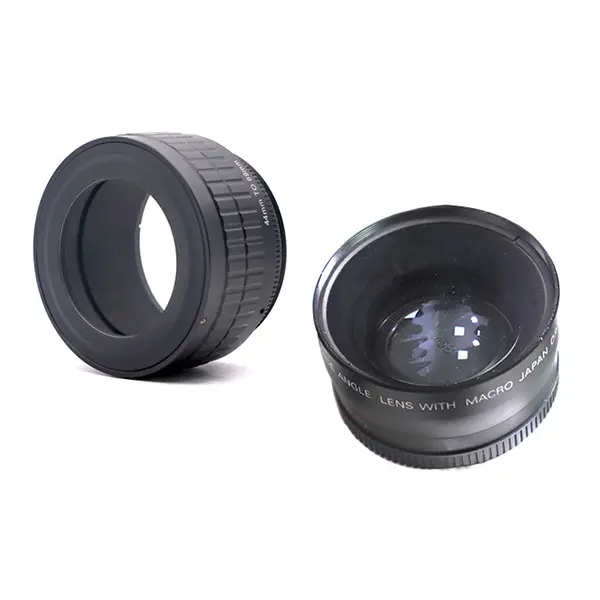
The customer specified AL6063-T6, full dimensional inspection, Class-A exposed surfaces without visible tool marks, black oxidation and production capacity above 3,000 pieces per day.
The structure contained more than 100 dimensions requiring inspection, about 60% below 0.02 mm tolerance, while visible surfaces also had to remain free of unacceptable machining marks before black finishing.
VMT recalculated in-process versus finished dimensions, developed dedicated tooling and fixtures, selected suitable cutting tools and optimized toolpaths to protect both precision geometry and Class-A external surfaces.
Three-dimensional inspection was used for full dimensional verification; the published case records a three-day prototype, shipment within one week and final shipment / assembly defect level controlled within 3%.
Quality control verifies whether the released machining process continues to produce housings that meet the drawing. VMT combines IQC, first-article inspection, in-process checks, CMM measurement, post-finish verification and final inspection, with 100% inspection of critical features when required by the control plan.
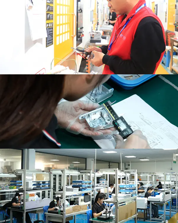
Customers choose VMT for responsive engineering support, reliable communication, stable quality and dependable follow-through from samples to repeat orders. The comments below show what customers said after receiving and testing parts manufactured by VMT.
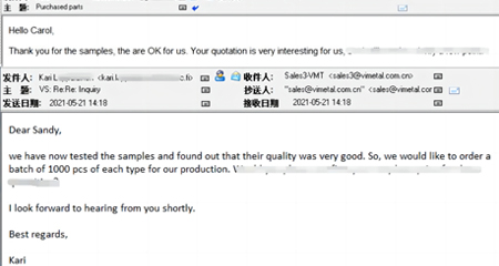
“We have now tested the samples and found out that their quality was very good. So, we would like to order a batch of 1000 pcs of each type for our production.”
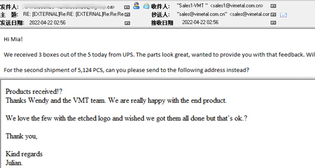
“Products received! Thanks Wendy and the VMT team. We are really happy with the end product.”

“Your parts were perfect, thank-you. I want to order a production quantity soon.”
Send the latest available files rather than waiting for a perfect package. The most useful information is the data that defines assembly, optical alignment, surface finishing and inspection.
A: We begin with the functional datum scheme in your drawing rather than treating each bore or face independently. Critical seats, bores, sensor faces and mounting holes are assigned to a setup and inspection sequence that preserves their relationship. Suitable features can be reviewed for tighter control, including ±0.005 mm capability where geometry and measurement allow, and CMM verification is used when datum-to-feature relationships are the real acceptance requirement.
A: Apply tight tolerances only to features that protect function: lens seats, sensor datums, sealing interfaces, connector locations and critical mating fits. VMT can review suitable critical features down to ±0.005 mm, but putting that tolerance on every wall, pocket and cosmetic surface increases machining and inspection cost without improving assembly. Send the mating-part relationship and we can help separate functional dimensions from general enclosure geometry.
A: We review wall distribution, stock-removal ratio, fixture support and the order in which critical faces are finished. When risk is high, roughing and final finishing are separated so the housing can stabilize before precision features are completed. Clamp force is controlled around thin sections, and free-state inspection after release helps catch geometry that appears acceptable only while the fixture is holding it.
A: The finishing requirement is reviewed before final machining. Critical bores, threads, sealing faces and electrical-contact areas are identified for masking, machining allowance or finished-condition inspection according to the drawing. For assembly-critical threads and fits, post-finish gauges or dimensional checks can be added so the part is accepted in the condition in which your assembly team will actually receive and use it.
A: Use 5-axis when angled optical interfaces, deep multi-face geometry or datum relationships make repeated setup transfers a real accuracy or access risk. If the housing can be completed with indexed 3/4-axis setups without compromising critical relationships, that route may reduce machine cost. VMT reviews tool access, setup count and tolerance stack before recommending the process instead of automatically quoting every complex housing as 5-axis work.
A: We inspect the dimensions that create the sealing interface: groove width, depth and position, mating-face geometry, fastener relationship and any drawing-defined flatness requirement. That verifies the machined structure, but it is not the same as certifying a finished device to a waterproof or ingress-protection rating. If your project requires pressure, leak or IP testing, include the validation requirement in the RFQ so it can be reviewed separately.
A: 6061-T6 is usually the practical baseline for machinability and anodizing, 7075-T6 increases strength and stiffness, magnesium can reduce mass further but requires careful corrosion protection, Grade 5 titanium offers high strength-to-weight ratio at higher machining cost, and Invar 36 is chosen when thermal dimensional stability matters more than low weight. The correct choice depends on your load, temperature range, finish and assembly interfaces.
A: Start by protecting only the datums and interfaces that drive function, then relax secondary pockets, exterior geometry and noncritical cosmetic dimensions where your design allows. Larger internal radii, practical cavity depth, fewer unnecessary setup changes and a finish plan defined before machining can also reduce cycle time. VMT’s DFM review looks for cost reduction that does not move the lens, sensor, sealing or mating features that actually control performance.
Send your CAD model, drawing and current project requirements. VMT can review manufacturability, machining route, material, finishing and inspection risk before quotation.
This guide helps engineers and sourcing teams review the design decisions that most directly affect machining risk, assembly fit, finished dimensions, inspection and repeat production.
A housing drawing should tell the machinist which surfaces and bores establish the mechanical relationship between the lens, detector, sensor, internal frame and external mounting interface. Without that hierarchy, every feature can be “within tolerance” while the assembled optical path still shifts.
VMT uses the functional datum hierarchy to plan setups, reduce unnecessary re-clamping and decide which relationships should be verified by CMM rather than by isolated size checks.
Define the primary datum around the most functionally stable mounting or optical reference, then use secondary and tertiary datums to lock rotation and lateral position. Where possible, dimension lens seats, sensor mounting holes and connector locations back to the same functional structure instead of chaining dimensions across cosmetic surfaces. During DFM, VMT uses that datum logic to decide which features should be completed in one setup, which setup transfers require probing or re-establishment, and where CMM inspection should report position relative to the drawing rather than just a local size.
For a multi-face housing, this is also the point where 5-axis machining can be justified. If several angled interfaces must remain related to one datum system, reducing re-clamping may protect accuracy. If those relationships are loose, 3/4-axis indexed machining may be the lower-cost route.
Large electronics cavities remove significant stock and can leave long unsupported walls. The engineering target is not simply “machine a thin wall,” but keep the housing stable after clamp force is removed and after finishing.
VMT’s published milling design guide uses 0.8 mm as a reference minimum wall thickness for metal parts, but imaging housings often need more depending on wall span, pocket depth, material and the location of precision interfaces. Thin cosmetic walls beside a critical lens bore deserve more attention than an isolated short wall because distortion can shift the optical reference.
Deep cavities also drive tool length and chatter. A larger internal corner radius allows a larger, stiffer cutter; VMT’s guide recommends an internal radius of at least one-third of cavity depth as a design reference. If the design cannot change, the process may require staged roughing, longer tools, reduced feed, additional setup time and more inspection—factors that should be visible in the quotation rather than discovered after production begins.
A 5-axis machine is valuable when it reduces setup error or enables geometry that cannot be reached efficiently otherwise; it is not automatically the best or lowest-risk answer for every imaging housing.
Use 3/4-axis milling for prismatic bodies, covers and indexed multi-side features when critical relationships can be maintained through controlled setups. Use 5-axis machining for angled optical interfaces, deep complex geometry or housings where repeated re-clamping would threaten datum relationships. Use CNC turning or turn-mill for cylindrical bodies, threaded sleeves, rings and concentric interfaces. Swiss machining is better reserved for smaller diameter parts such as sleeves, bushings, pins, threaded spacers and precision cylindrical components rather than the main housing body.
The DFM review should compare setup count, tool access, cycle time, inspection access and the cost of protecting functional dimensions. The best route is the one that meets the drawing with the least unnecessary complexity.
Applying the same tight tolerance to every feature makes a housing expensive without necessarily making the optical system better. Separate optical alignment, sealing and assembly dimensions from general enclosure geometry.
Suitable VMT critical features can be reviewed down to ±0.005 mm after material, geometry and measurement access are confirmed. That capability is most valuable on lens seats, mating diameters, shoulders, precision bores and sensor-related datums. A large external cosmetic pocket or nonfunctional wall usually does not need the same control.
When the customer can provide mating-part data, the engineering team can see whether a tolerance is protecting a press fit, clearance, optical axis, sealing compression or connector position. That context helps avoid two common RFQ problems: over-tolerancing every feature and under-defining the few features that actually determine whether the assembly works.
A precision housing is accepted in its finished state, so machining and finishing should be planned as one process rather than two unrelated supplier steps.
Mark critical bores, threads, electrical-contact surfaces, sealing faces and cosmetic areas before release. The finish plan should identify where coating buildup is acceptable, where masking is required, and which dimensions need post-finish verification. For black anodized optical housings, internal low-reflectivity areas may have a different functional purpose from external Class-A cosmetic surfaces, so they should not be treated with one generic appearance requirement.
This planning also reduces rework. If a bore is machined exactly to final size but the coating closes the fit, the part can be dimensionally correct before finishing and unusable afterward. By treating finished condition as part of DFM, VMT can align machining allowance, supplier finishing control and final inspection to the same drawing intent.
Environmental sealing depends on the whole interface—groove geometry, mating surface, fastener pattern and gasket design—not on a single groove-depth dimension.
Provide groove width, depth, corner conditions and datum references clearly, and avoid placing critical sealing geometry where inspection access is impossible. Mating-face flatness or profile should be specified only to the level required by the actual sealing design. If pressure, leak or IP validation is part of your project, that requirement should be stated separately from dimensional inspection because a machined groove passing CMM inspection is not, by itself, proof of a complete system rating.
When the enclosure uses multiple covers or a long perimeter seal, the screw pattern and local wall stiffness can also affect closure. Sharing the mating cover, gasket or seal geometry during RFQ helps the machining team understand why the interface is critical.
There is no single best imaging-housing material. The right choice depends on whether the project is limited by mass, structural stiffness, harsh environment, finishing or temperature-induced dimensional change.
6061-T6 is often the practical starting point for aluminum housings because it machines well and accepts anodizing. 7075-T6 supports higher strength and stiffness when thinner sections or load demand it. 6063 is attractive for visible anodized structures, while 6082 is useful for stronger structural aluminum requirements. Magnesium can reduce weight further but needs a suitable corrosion-protection plan. Grade 5 titanium provides high strength-to-weight performance with higher machining cost. 304/316 stainless steel supports rigid, corrosion-resistant mounts and inserts. Invar 36 belongs in temperature-sensitive optical structures where dimensional stability matters more than mass.
Material selection should happen before tolerance and finishing decisions are finalized because the alloy changes tool strategy, distortion risk, coating options and inspection behavior.
A prototype proves more than the shape of one part. It should validate the setup, fixture, toolpath, finishing allowance and inspection method that will be repeated in production.
Document the approved drawing revision, fixture concept, critical tools, setup sequence, finish specification and inspection plan after first-article approval. When production begins, in-process inspection should watch the characteristics most likely to drift through tool wear, thermal change or fixture variation. VMT’s quality workflow includes IQC, FAI, IPQC, surface inspection, FQC and OQC, while critical features can receive 100% inspection when the project requires it.
This separation between process control and quality verification is important: process control tries to prevent the variation; inspection proves whether the released part still meets the drawing. Both are needed when moving from a successful prototype to repeat orders.
The fastest useful quotation comes from understanding what the housing must locate, seal, protect and connect—not just receiving a STEP file with no functional context.
Send the 3D model, 2D drawing, material, finish, prototype and production quantities, plus any mating-part data that defines critical fits. Identify lens seats, sensor datums, sealing grooves, connector positions and surfaces that must remain cosmetic after finishing. If tolerance or material is still open, mark it for engineering review rather than over-specifying a value simply to complete the drawing.
For early-stage designs, even an incomplete CAD model is useful if you tell VMT which interfaces cannot move. That lets the DFM discussion focus on manufacturability, machining cost and inspection risk while preserving the functions your design team has already locked.

 2024-08-02
The manufacturer is strongly recommended. In the past few years of cooperation we have ordered several machined products from aluminum and stainless steel. These products are manufactured in compliance with tolerance requirements and require product finish. Now I have ordered another one. The service is excellent and any questions can be answered and resolved in time.
 2021-05-13
The dimensions are all customized according to my drawings no tolerance issues and the parts are delivered on time. I am very satisfied with it.
 2021-04-06
I pay much attention to the surface treatment aspect of this product. I was a little worried about the cooperation at the beginning. I am very satisfied with the product now and hope to cooperate for a long time.
 2022-09-22
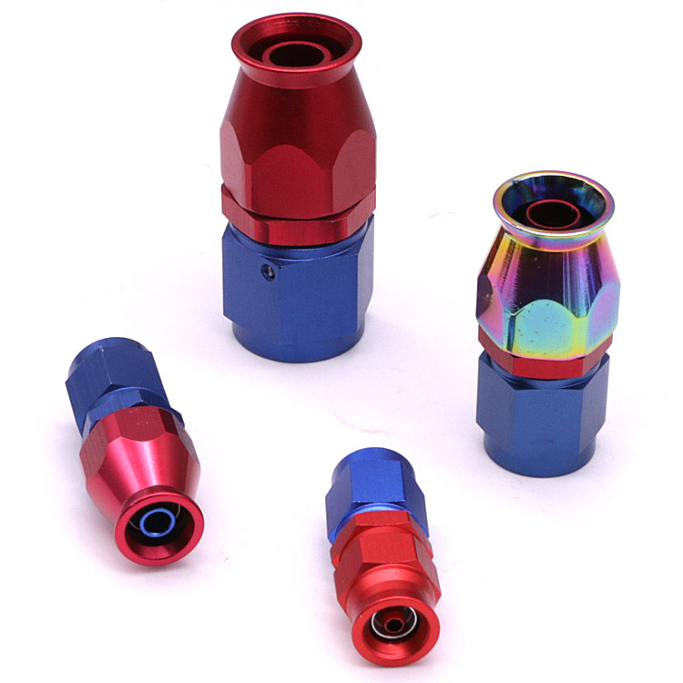
AN8 Straight PTFE Hose End Fitting for PTFE Fuel Line Fitting Adapter Black Blue Red


 +86 15099911516