16 years one-stop China custom CNC machining parts factory

Hey there I’m VMT Sam!
With 25 years of CNC machining experience we are committed to helping clients overcome 10000 complex part-processing challenges all to contribute to a better life through intelligent manufacturing. Contact us now
 1101 |
Published by VMT at Aug 04 2026 | Reading Time:About 8 minutes
1101 |
Published by VMT at Aug 04 2026 | Reading Time:About 8 minutes


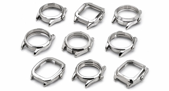
A watch case may look like a compact cosmetic component, but small errors in its movement cavity, crystal seat, gasket groove, lugs, threads or surface finish can cause assembly failure, water-resistance risks, rework and inconsistent production.
A controlled CNC watch case manufacturing process helps identify and reduce these risks before batch production begins.
A CNC watch case is normally manufactured through drawing and DFM review, material selection, process planning, datum and fixture design, rough machining, semi-finishing, precision machining, sealing-feature machining, deburring, surface finishing and final inspection.
Each stage must protect:
A watch case is not simply a decorative metal shell. It positions and protects the movement or electronic module while connecting the crystal, bezel, case back, gasket, crown, pushers, sensors and strap.
A dimensionally correct case may still fail if the crystal fit is unstable, the gasket groove does not provide suitable compression, the crown opening is misaligned, the lugs do not match the bracelet or polishing rounds a critical edge.
The following guide explains what should be controlled at every stage, which manufacturing problems may occur and how you can move from a functional prototype to repeatable production.
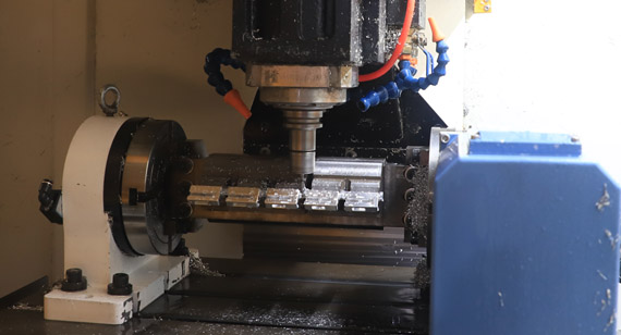
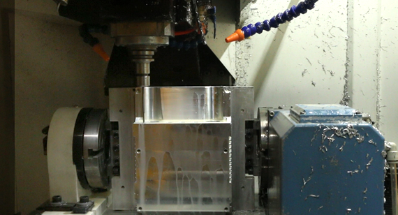
VMT provides custom CNC watch case machining services for watch brands, product developers and OEM manufacturers, supporting custom projects from drawing review and prototype verification to surface finishing, inspection and batch production.
Successful watch case manufacturing requires the supplier to control dimensional accuracy, assembly relationships, sealing interfaces, cosmetic consistency and production repeatability at the same time.
Dimensional and Assembly Accuracy
The movement cavity, crystal seat, bezel interface, case-back connection, lug spacing, crown-hole position and threaded features must fit the mating components defined by the customer’s drawings.
A single dimension may appear acceptable when measured independently but still cause assembly problems when combined with other dimensional variations.
For example, the crystal-seat diameter may be within tolerance, but an error in roundness, depth, concentricity or edge condition may still cause:
A DFM review should therefore evaluate tolerance stack-up and functional relationships rather than checking individual dimensions only.
Water-Resistant Sealing Interfaces
The gasket groove, case-back sealing surface, crystal interface, crown tube, pusher openings and sensor windows may all affect the conditions required for a water-resistant assembly.
CNC machining can control:
However, the final water resistance of the assembled watch also depends on gasket selection, gasket compression, lubrication, crystal installation, crown components, assembly procedures and pressure or leak testing.
CNC machining creates the required geometry, but it cannot independently guarantee the water resistance of the complete assembled watch.
Cosmetic Surface Consistency
Watch cases frequently combine:
These finishes must be considered during machining because polishing removes material, coatings affect effective feature size and manual finishing can soften edges or move finish boundaries.
Prototype-to-Production Repeatability
One prototype may be produced through careful manual adjustment, but batch production requires repeatable:
The objective is not only to manufacture one acceptable watch case. It is to maintain the same fit, appearance and functional performance across every approved production batch.
| Critical feature | Possible customer problem | Recommended manufacturing control |
| Movement or electronics cavity | Internal components cannot be installed or move after assembly | Control cavity profile, locating shoulders, clearance, screw positions and reference surfaces |
| Crystal seat | Crystal is loose, tilted, damaged or difficult to install | Control diameter, roundness, depth, flatness, surface condition and fit relationship |
| Bezel interface | Uneven gap, loose rotation or visible misalignment | Control concentricity, retaining geometry, step height and mating dimensions |
| Case-back thread | Cross-threading, unstable engagement or sealing failure | Inspect thread form, pitch, lead-in, engagement length and mating-part fit |
| Case-back seating surface | Uneven closure or insufficient gasket contact | Control flatness, surface finish and relationship to the gasket groove |
| Gasket groove | Excessive or insufficient gasket compression | Control width, depth, radius, concentricity, burrs and surface condition |
| Crown-tube opening | Stem or crown cannot align with the internal movement | Control position, diameter, angle, perpendicularity and internal finish |
| Pusher holes | Button resistance, leakage or visible misalignment | Control position, coaxiality, diameter, counterbore and sealing interface |
| Lug holes | Strap, bracelet or spring bar cannot be assembled | Control spacing, position, coaxiality, hole diameter and burr condition |
| Sensor or display opening | Poor sealing, poor alignment or adhesive failure | Control profile, flatness, opening position and bonding or gasket surface |
| Decorative chamfers | Chamfers disappear or become uneven after polishing | Reserve controlled polishing allowance and protect critical edges |
| Mixed-finish boundary | Brushed and polished areas overlap or appear uneven | Define finish boundaries, masking methods, processing order and approved samples |
| Stage | Main work | Critical control |
| 1. DFM review | Review drawings, CAD models, tolerances and assembly relationships | Tolerance stack-up, missing specifications and manufacturability risks |
| 2. Material selection | Select material grade and suitable blank | Weight, strength, corrosion resistance, finish and dimensional stability |
| 3. Manufacturing-route planning | Choose billet, bar, forged blank, casting or near-net-shape blank | Tooling cost, production volume, material waste and machining allowance |
| 4. Datum and fixture planning | Define functional datums, setups and workholding | Repeatable positioning, tool access and clamping distortion |
| 5. Rough machining | Remove bulk material and establish the main geometry | Heat, residual stress, wall deformation and finishing allowance |
| 6. Semi-finishing | Stabilize the part before final dimensions are machined | Material movement, wall thickness, flatness and datum verification |
| 7. Precision machining | Produce assembly and functional features | Fit, position, profile, concentricity and surface condition |
| 8. Sealing-feature machining | Machine gasket grooves and sealing surfaces | Groove geometry, burrs, roughness and mating-surface flatness |
| 9. Micro-feature and thread machining | Produce holes, threads, branding and detailed features | Tool runout, thread quality, burrs and feature position |
| 10. Deburring and pre-finish inspection | Remove sharp edges and verify machined dimensions | Protection of threads, seals, cosmetic edges and finishing allowance |
| 11. Surface finishing | Polish, brush, blast, anodize, passivate or apply PVD | Texture, color, gloss, coating thickness, masking and edge retention |
| 12. Final inspection and production control | Inspect dimensions, function and appearance | Assembly acceptance, batch consistency, traceability and packaging |
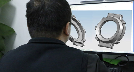
A reliable CNC watch case manufacturing process begins before material is placed in the machine.
The 3D CAD model defines the primary geometry, while the 2D drawing should communicate:
The manufacturer should review both files together.
Important DFM Review Points
The DFM review should evaluate:
Potential problems should be identified before quotation and programming, not after the first machined sample is completed.
Define Critical Dimensions Before Quotation
Not every watch case dimension requires the same tolerance.
Dimensions can be divided into three groups.
Critical Functional Dimensions
These dimensions directly affect:
Assembly Dimensions
These include:
General Dimensions
These include non-critical external profiles, clearance areas and hidden relief features that do not directly affect assembly or sealing.
Applying very tight tolerances to every dimension increases:
Tighter tolerances should be applied only where they create measurable functional value.
Engineering tip: Send mating-component drawings or samples when possible. Reviewing only the watch case may not reveal tolerance-stack problems between the case, crystal, bezel, case back, gasket, movement holder, crown, pushers or strap.
Include Surface Finishing in the DFM Review
Surface finishing should not be decided after machining is completed.
The drawing or approved finishing standard should identify:
This allows the machining team to reserve suitable finishing allowance and protect critical dimensions.
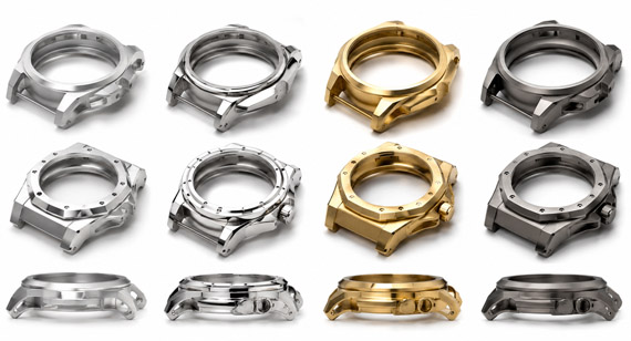
The best material depends on:
Common CNC Watch Case Materials
| Material | Typical applications | Machining considerations | Common finishes |
| 316L stainless steel | Mechanical, dive, fashion and premium watches | Higher cutting force and tool wear than aluminum; polishing allowance is important | Polishing, brushing, blasting, passivation and PVD |
| 904L stainless steel | Premium corrosion-resistant watch cases | More demanding machining and finishing; higher material and processing cost | Mirror polishing, brushing and passivation |
| Grade 2 titanium | Lightweight premium, sports and outdoor watches | Burr control, heat management and cosmetic protection are important | Brushing, blasting, polishing and PVD |
| Grade 5 titanium | High-strength sports and premium watches | Greater tool wear and localized heat than commercially pure titanium | Blasting, brushing, polishing and PVD |
| 6061 aluminum | Smartwatches, sports watches and lightweight cases | Good machinability, but thin walls may deform after heavy stock removal | Anodizing, blasting, brushing, painting and laser marking |
| 7075 aluminum | Higher-strength lightweight cases | Residual stress and dimensional stability require careful process planning | Anodizing, hard anodizing and blasting |
| Brass | Decorative, vintage-style and limited-edition watches | Oxidation, coating adhesion and handling marks must be controlled | Polishing, plating, PVD and protective coating |
| Bronze | Vintage and decorative watches | Natural patina and color development must be considered | Polishing, brushing and protective coating |
Stainless Steel Watch Cases
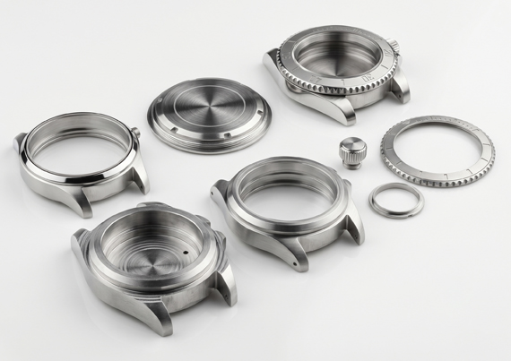
316L stainless steel is frequently selected when the customer requires:
Stainless steel requires suitable tooling, controlled cutting parameters and heat management.
Poor machining conditions may cause:
For additional information about finishing stainless steel cases, see the guide to stainless steel watch case polishing.
Aluminum Watch Cases
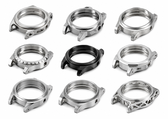
Aluminum alloys are suitable for lightweight smartwatches, sports watches and electronic wearable housings.
6061 generally offers:
7075 provides higher strength but may require more careful control of:
The final anodized appearance depends on material grade, material batch, machining condition, blasting or brushing process and coating parameters.
Titanium Watch Cases
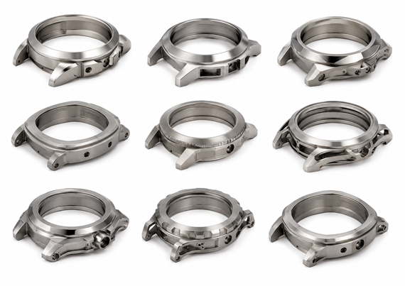
Titanium is used when a project requires:
Titanium machining requires:
Its machining and tooling costs are normally higher than those of common aluminum alloys.
Brass and Bronze Watch Cases
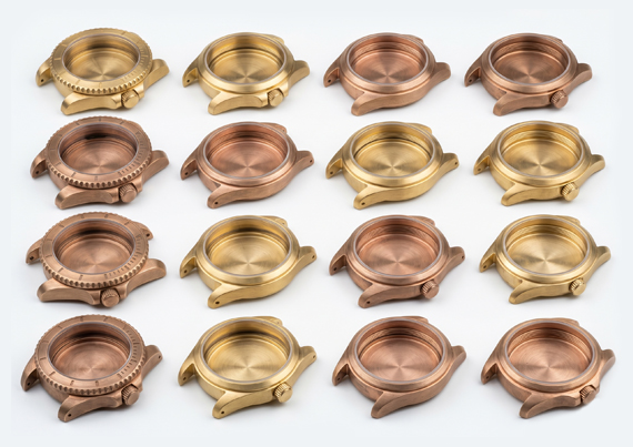
Brass and bronze may be used for:
The production plan must consider:
Material Selection Summary
| Material | Main customer value | Primary manufacturing risk |
| Stainless steel | Premium weight, durability and polished appearance | Tool wear, heat, burrs and polishing control |
| Aluminum | Low weight, efficient machining and anodized colors | Thin-wall deformation and anodizing variation |
| Titanium | Premium lightweight performance and corrosion resistance | Heat, tool wear and longer machining time |
| Brass | Decorative appearance and good detail definition | Oxidation and coating protection |
| Bronze | Distinctive vintage appearance and natural patina | Color and patina consistency |
Changing the material after prototype approval may require new cutting parameters, tooling, polishing trials, coating validation and dimensional compensation.
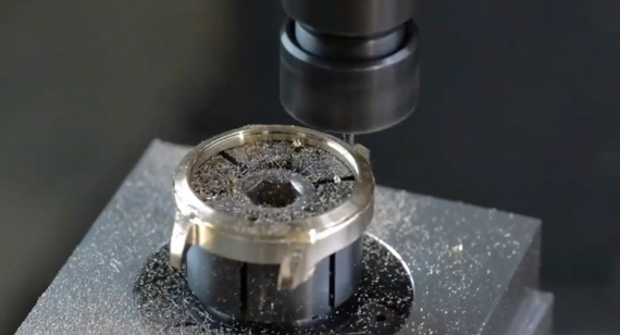
Not every watch case must be machined entirely from a solid rectangular block.
Depending on geometry, material, quantity and target cost, the production route may include:
Full CNC Machining From Solid Material
Full machining from billet, plate or bar is often suitable for:
The main advantage is design flexibility. Geometry can be revised through the CNC program without modifying a forging or casting tool.
Forged or Cast Blank Followed by CNC Machining
At higher and stable production volumes, a forged or cast blank may reduce:
However, this route may require:
CNC Turning and Milling
Round watch cases may combine CNC turning and milling.
Turning may be used for:
Milling may then produce:
Irregular, square or highly sculpted watch cases generally require multi-axis milling.
Cases with compound curves, angled lugs or multiple directional features may benefit from 5-axis CNC machining services.
Five-axis machining is not automatically required for every case. The correct process is the simplest stable route capable of meeting the specified geometry, tolerance, appearance and production quantity.
For a broader comparison, see smartwatch case manufacturing methods.
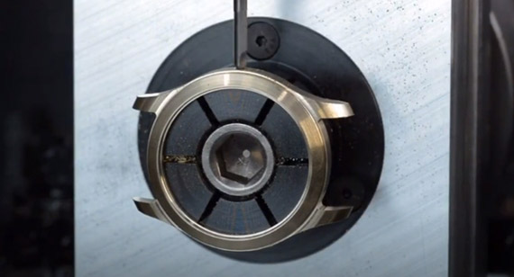
A watch case commonly requires several machining orientations.
Every time the part is removed and repositioned, the manufacturer must maintain the relationship between:
This makes datum selection and fixture design critical.
Select Functional Datums
Datums should be based on assembly function.
A manufacturing plan may use:
Unnecessary datum changes can introduce errors in:
The manufacturing datum strategy should support the functional datums defined in the drawing.
Design Workholding for Thin-Wall Geometry
After the internal cavity is machined, a watch case can become flexible.
Excessive clamping force may distort the part during machining. The part may appear correct while clamped and then move outside tolerance after release.
Possible workholding methods include:
The fixture must:
Select the Appropriate CNC Configuration
Simple round cases may use turning and 3-axis milling.
More complex cases may require:
More machine axes do not automatically provide a better result.
The selection should consider:
CAM Programming and Tool Selection
CAM planning should control:
Short and rigid tools are preferred where geometry allows.
Small tools should be used only where the design requires narrow grooves, small radii or detailed features, because small tools are more sensitive to runout, wear and breakage.
Rough machining removes most of the material and creates the initial internal and external shapes.
It can also introduce one of the most common watch-case manufacturing problems: deformation after heavy stock removal.
Why Watch Cases Deform
Material blanks may contain residual stress from:
When material is removed unevenly, internal stress can be redistributed.
Thin walls, deep cavities, excessive cutting heat and high clamping pressure can increase deformation.
Possible results include:
Rough-Machining Controls
The production plan may use:
The case should not normally be taken directly from heavy roughing to its final dimensions.
Enough material should remain for semi-finishing and final machining to correct minor movement.
Engineering tip: Specify extremely thin walls only where the product genuinely requires them. Thin walls can increase fixture complexity, machining time, deformation risk and inspection difficulty.
Semi-finishing brings the watch case closer to its final geometry while leaving controlled material on critical surfaces.
This stage provides an opportunity to check the part after most internal stress has been released.
The manufacturer may inspect:
Semi-finishing is especially valuable for:
Critical sealing and assembly features should not be completed before the part has demonstrated acceptable dimensional stability.
After roughing, stabilization and intermediate inspection, the functional geometry is machined to its final or pre-finishing dimensions.
Movement or Electronics Cavity
The internal cavity must provide sufficient clearance while positioning the movement, display, sensor assembly, battery or electronics frame correctly.
Important controls may include:
The cavity should not be tighter than the assembly requires. Suitable clearance reduces assembly resistance and unnecessary machining cost.
Crystal Seat
The crystal interface may use:
The manufacturer should control:
Incorrect dimensions may cause:
Bezel Interface
A fixed or rotating bezel may require control of:
Inspection should reflect whether the bezel is:
Case-Back Interface
The case back may use:
Relevant requirements may include:
Thread quality should be checked with suitable gauges or an approved mating part rather than visual inspection alone.
Lug and Strap Interface
The lugs affect appearance, strap fit and structural performance.
Important controls include:
When the bracelet or strap is manufactured by another supplier, both suppliers should work from the same interface drawing or approved assembly sample.
Crown-Tube and Pusher Features
The crown tube, stem and pusher openings must align with the movement or internal electronic assembly.
Key controls include:
A visually acceptable hole may still cause assembly resistance if its axis does not match the internal component.
Gasket grooves are small features, but they have a significant effect on sealing and assembly.
Gaskets may be used around:
Critical Gasket-Groove Features
The drawing should define:
A groove that is too shallow may over-compress the gasket.
A groove that is too deep may provide insufficient compression.
Burrs, tool marks and damaged edges may interfere with gasket installation or sealing.
Protect the Sealing Surface
The manufacturer should avoid:
The complete assembled watch should still undergo the required pressure, vacuum or leak testing after assembly.
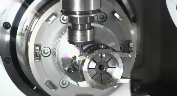
Watch cases may contain:
Small tools are sensitive to:
Thread Control
Threads may be produced by:
The selection depends on:
Thread inspection may include:
The drawing should distinguish between:
Laser Engraving and Branding
Logos, serial numbers and identification markings can be added before or after surface finishing, depending on the required effect.
The specification should define:
Branding should be treated as part of cosmetic control and production traceability rather than as an isolated decorative operation.
Surface finishing should not be used to hide unresolved machining defects.
Before polishing, brushing, blasting, anodizing or PVD, the watch case should be deburred, cleaned and dimensionally inspected.
Areas Requiring Careful Deburring
Special attention should be given to:
Deburring must remove sharp edges without:
Possible deburring and cleaning methods include:
Pre-Finishing Inspection
Before the case moves to surface finishing, inspect:
This prevents an expensive finish from being applied to a dimensionally unacceptable part.
Define Cosmetic Boundaries
When the case combines mirror-polished and brushed surfaces, the drawing or approved sample should show:
An approved physical finish sample should be established before batch production. Written descriptions such as “mirror polish” or “fine brushing” may not define the expected appearance precisely enough.
The correct finish depends on the case material, brand appearance, wear requirement and assembly tolerance.
VMT provides multiple surface finishing services for CNC machined parts, including polishing, brushing, blasting, anodizing, passivation, plating, PVD coating and laser engraving.
Watch Case Surface Finish Comparison
| Finish | Suitable materials | Main customer value | Primary manufacturing risk |
| Mirror polishing | Stainless steel, titanium, brass and bronze | Premium reflective appearance | Edge rounding, waves, scratches and dimensional loss |
| Brushing | Stainless steel, titanium and aluminum | Controlled directional texture | Inconsistent grain direction and uneven boundaries |
| Bead or sand blasting | Aluminum, titanium and stainless steel | Uniform matte appearance | Uneven texture, contamination and handling marks |
| Anodizing | Aluminum | Color, corrosion protection and decorative texture | Color variation, rack marks and dimensional change |
| Hard anodizing | Aluminum | Higher surface hardness and wear resistance | Greater dimensional change and limited color options |
| PVD coating | Stainless steel and titanium | Decorative color and surface performance | Adhesion, color consistency, dust and fit change |
| Passivation | Stainless steel | Improved corrosion resistance after machining | Inadequate cleaning and contamination control |
| Laser engraving | Most suitable metals | Branding and traceability | Position, contrast, depth and cosmetic distortion |
Mirror Polishing
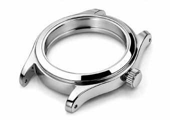
Mirror polishing normally involves progressive removal of:
The polishing team must protect:
Excessive polishing may:
Polishing Allowance
The process plan should define:
Machining and polishing should be planned together.
Brushing
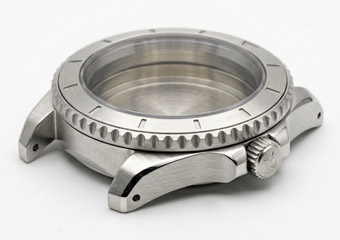
Brushed surfaces require control of:
When brushed and polished areas meet, the transition should follow an approved boundary.
Uncontrolled finishing may create:
Bead Blasting
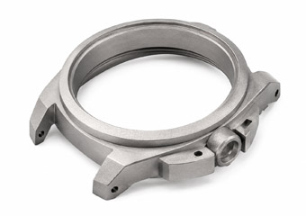
Bead blasting can create a uniform matte appearance and reduce the visibility of minor machining marks.
Consistency depends on:
Critical fits, threads and sealing surfaces may require masking.
Anodizing
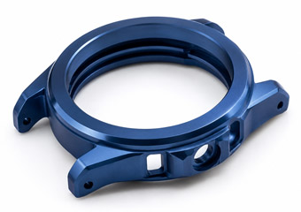
Anodizing is commonly used for aluminum watch cases.
The final appearance depends on:
A physical color sample is more reliable than a digital image.
Precision holes, threads and fits may require:
PVD Coating
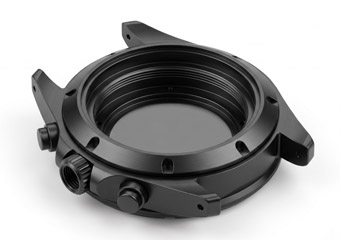
PVD coating can provide decorative colors and improve surface performance on stainless steel or titanium watch cases.
The result depends heavily on surface preparation.
The process should control:
Mixed Polished and Brushed Surfaces
Luxury watch cases frequently combine polished chamfers with brushed or satin surfaces.
This requires:
Mixed finishes should be evaluated during quotation because they can add substantial manual work and cosmetic inspection time.
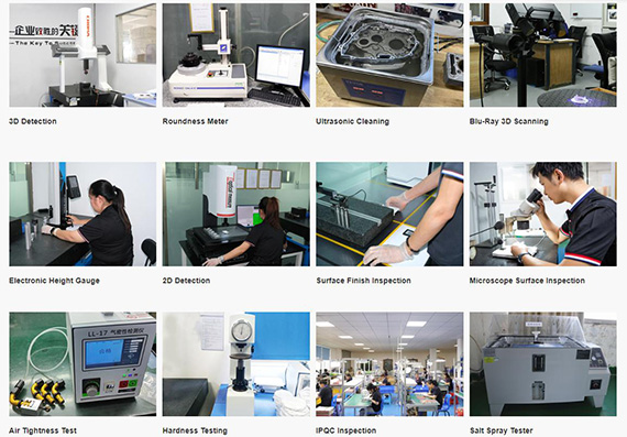
Final inspection should evaluate more than the external dimensions of the case.
A complete inspection plan should be based on how the case will assemble and function.
VMT’s CNC machining quality-control process can include material inspection, first-article inspection, in-process checks, final dimensional inspection and outgoing cosmetic inspection.
Dimensional Inspection
Depending on the drawing, inspection may include:
Possible measuring equipment includes:
Inspection Method and Customer Value
| Inspection item | Possible inspection method | Customer value |
| Crystal and bezel seat | Bore gauge, CMM or optical measurement | Stable assembly force and consistent visible gap |
| Movement cavity | CMM, bore gauge or functional sample | Reliable internal-component positioning |
| Case-back interface | CMM, thread gauge or mating-part test | Smooth engagement and reliable closure |
| Gasket groove | Optical measurement, CMM or profile inspection | Controlled gasket position and compression |
| Crown opening | CMM, pin gauge or fixture verification | Alignment with the movement and crown components |
| Lug holes | Pin gauge, CMM or optical inspection | Reliable strap, bracelet and spring-bar assembly |
| Flatness | CMM or surface-plate inspection | Stable sealing and assembly contact |
| Surface roughness | Surface-roughness tester | Suitable sealing surface or cosmetic preparation |
| Threads | Go/no-go gauge and mating-part test | Reduced assembly failure and thread damage |
| Cosmetic finish | Controlled lighting and approved sample | Consistent appearance between parts and batches |
| Overall profile | CMM or optical profile measurement | Correct product appearance and assembly relationship |
| Wall thickness | CMM, ultrasonic method or suitable gauge | Reduced deformation and structural risk |
Geometric Inspection
Important geometric controls may include:
These controls are particularly important when several components share the same centerline or sealing plane.
Functional Inspection
Functional verification may include:
Dimensional inspection confirms the drawing. Functional verification confirms that the drawing and mating components work together.
Cosmetic Inspection
Cosmetic inspection should be performed under controlled conditions.
The standard should define:
Inspectors should check for:
After approval, finished cases should be individually protected to prevent metal-to-metal contact or cosmetic damage during storage and shipment.
| Manufacturing stage | Common risk | Recommended control |
| Drawing review | Missing tolerance or incomplete assembly information | DFM and tolerance-stack review |
| Material preparation | Incorrect grade or dimensionally unstable blank | Material verification and suitable stock selection |
| Fixture design | Part movement or clamping distortion | Form-fitting fixtures and controlled clamping |
| Rough machining | Thin-wall deformation | Balanced stock removal and staged machining |
| Semi-finishing | Residual movement remains undetected | Unclamped inspection and controlled finishing allowance |
| Repositioning | Datum shift between setups | Repeatable locating features and fixture verification |
| Precision machining | Misaligned crystal, case-back or crown features | Functional datums and in-process measurement |
| Gasket-groove machining | Incorrect depth, width or burr condition | Suitable tooling and pre-finish inspection |
| Thread machining | Poor engagement or damaged lead-in | Thread gauges and mating-part checks |
| Polishing | Rounded edges and dimensional loss | Defined allowance and protected features |
| Brushing | Inconsistent direction or transition lines | Approved master sample and controlled process |
| Anodizing or PVD | Tight fits, color variation or coating defects | Compensation, masking and finish validation |
| Batch production | Dimensional or appearance drift | First-article approval and process control |
| Packaging | Scratches and contact damage | Individual protective packaging |
| Problem | Likely cause | Customer impact | Prevention method |
| Thin-wall deformation | Unbalanced material removal or excessive clamping | Poor fit, flatness error and unstable sealing | Balanced roughing, controlled fixtures and semi-finish inspection |
| Loose or tight crystal fit | Seat diameter, roundness or finishing allowance is incorrect | Difficult assembly, damage or insufficient retention | Inspect functional fit before and after finishing |
| Uneven bezel gap | Concentricity or step-height error | Visible cosmetic inconsistency | Use common datums and inspect mating dimensions |
| Poor case-back engagement | Thread, flatness or lead-in error | Cross-threading, uneven closure or leakage risk | Gauge threads and perform mating-part tests |
| Unstable gasket compression | Incorrect groove geometry | Sealing inconsistency | Control groove width, depth, radius and surface condition |
| Misaligned crown | Position or angular error | Assembly resistance and poor operation | Use functional datums and assembly checks |
| Lug-hole assembly problem | Hole position, coaxiality or burr error | Strap or spring bar cannot be installed | Use pin gauges, optical inspection and controlled deburring |
| Rounded cosmetic edges | Excessive grinding or polishing | Loss of design definition | Reserve polishing allowance and protect edges |
| Uneven brushing | Inconsistent direction, pressure or abrasive condition | Visible batch variation | Use approved samples and standardized procedures |
| Anodizing or PVD variation | Base-surface or process variation | Inconsistent color and gloss | Control material, preparation, coating batch and color limits |
| Scratches after finishing | Poor handling, inspection or packaging | Cosmetic rejection | Use separated trays, protective film and controlled handling |
| Batch dimensional drift | Tool wear or fixture variation | Assembly inconsistency | Monitor tool life and inspect critical dimensions during production |
For a deeper explanation of these problems, see common CNC watch case machining problems and solutions.
The price of a custom CNC watch case cannot be determined only by its outside diameter or material weight.
The complete manufacturing route affects the quotation.
Material and Blank Cost
Different materials have different:
A large solid blank may also generate substantial material waste when the case contains a deep internal cavity.
Number of Setups
Every additional setup may require:
Reducing the number of setups can lower cost and accumulated positioning error, provided that the selected setup remains stable.
Geometry and Tool Access
Cost may increase because of:
Tolerance and Inspection Requirements
Tight tolerances may require:
Tight tolerances should be concentrated on features affecting function, sealing, alignment and assembly.
Surface-Finishing Complexity
A uniform blasted finish is generally easier to control than a case combining:
Production Quantity
Prototype cost per part is usually higher because programming, fixtures, setup and inspection are distributed across only a few pieces.
Larger batches may reduce unit machining cost but require:
Packaging
Finished watch cases are cosmetic parts.
Individual protection may be required to prevent:
Lead time depends on more than CNC cycle time.
Important factors include:
A raw-machined prototype is normally faster than a fully polished, PVD-coated and cosmetically approved sample.
When requesting a quotation, provide the complete drawing package, material, quantity, surface finish and target delivery date together. This allows the supplier to identify the actual project critical path.
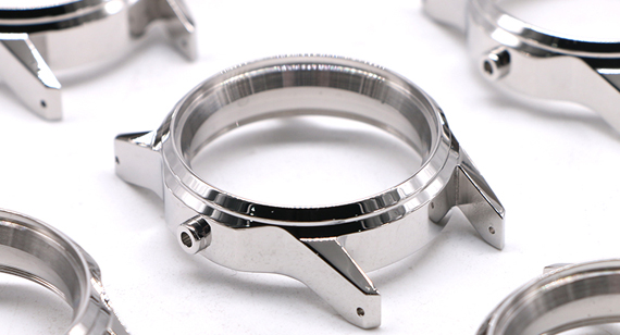
A visually acceptable prototype is not the end of the development process.
The prototype should validate:
A raw-machined prototype may confirm dimensions, but at least one completely finished prototype should normally be reviewed before mass-production approval.
Polishing, blasting, anodizing and PVD can reveal problems that are not visible on the unfinished part.
Recommended Development Sequence
First-Article Approval
Before batch production, confirm:
Create Production Standards
The customer and manufacturer should agree on:
These standards prevent the production, finishing, inspection and customer teams from using different definitions of an acceptable watch case.
Batch Production Control
Repeatability may be supported through:
Critical dimensions may require 100% inspection, while stable non-critical features may be inspected according to an agreed sampling plan.
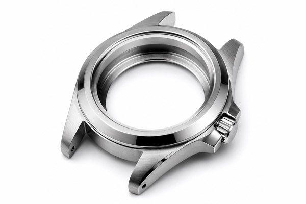
A watch brand developing a new 316L stainless steel case may initially focus on the external shape, logo position and polished appearance.
During DFM review, the manufacturer may identify:
The production plan can be improved by:
The first prototype is used to validate assembly, sealing interfaces and appearance.
After the brand approves the revised geometry and finish sample, the same datum, fixture, inspection and polishing standards can be transferred to a pilot batch.
The value of DFM is not only reducing machining cost. It reduces the risk that assembly, sealing and cosmetic problems are discovered after expensive surface finishing or product assembly.
VMT supports custom watch case projects from drawing review and prototype machining through surface finishing, inspection and repeat production.
VMT does not supply standard watch cases from a catalogue. Components are manufactured according to the customer’s drawings, CAD models, samples and assembly requirements.
Engineering and DFM Review
Before machining, the engineering team can review:
This helps identify manufacturing and assembly risks before they cause machining changes or finished-part rework.
Prototype and Fixture Planning
The prototype can be planned around functional datums that may also support pilot and batch production.
After design approval, the fixture and inspection strategy can be optimized for:
CNC Machining Support
Depending on the geometry, VMT can coordinate:
Typical watch case features include:
Process and Inspection Control
In-process measurement can identify dimensional movement before the case reaches surface finishing.
Final inspection can include:
Surface-Finishing Coordination
Machining and finishing should be planned as one connected process.
Depending on material and design requirements, VMT can coordinate:
Protective Packaging
Finished watch cases should be separated and protected to reduce:
The goal is not only to machine the external case profile. It is to help reduce assembly risk, protect cosmetic quality and maintain a repeatable result from prototype approval to later production batches.
Providing complete project information helps the supplier prepare a more accurate quotation and DFM review.
Please include:
Common 3D formats include:
The 2D PDF or DWG drawing should define tolerances, threads, finish requirements and inspection criteria.
CNC watch case manufacturing is a connected engineering process covering DFM review, material selection, process planning, fixture design, rough machining, semi-finishing, precision machining, sealing-feature control, deburring, surface finishing and final inspection.
The most important objective is not simply machining the external shape.
The manufacturer must control the relationships between:
By identifying these risks during DFM review, validating a fully finished prototype and establishing production and inspection standards before batch manufacturing, you can reduce assembly problems, sealing risks, cosmetic rejection and expensive design changes.
Developing a luxury watch, sports watch, smartwatch or custom OEM case?
Send VMT your 2D drawings, 3D CAD models, material specification, target quantity and surface-finish reference.
Our engineering team can review:
Request a quotation and DFM review for your custom CNC watch case project, from functional prototypes and finish validation to repeatable batch production.
Send your 2D drawings, 3D CAD models, material specification, target quantity, critical tolerances, mating-component information and surface-finish reference. VMT will review your custom CNC watch case project and provide a practical DFM solution and quotation.
All information and uploaded files are secure and confidential.
1 Tell us what you need
2 Get solution & quote
3 Approve production
Email: inquiry@vimetal.com.cn
How are CNC watch cases manufactured?
A CNC watch case is normally manufactured through DFM review, material preparation, process and fixture planning, rough machining, semi-finishing, precision machining, gasket-groove machining, deburring, surface finishing and final inspection.
The exact route depends on the material, geometry, assembly method, finishing requirement and production quantity.
What materials are commonly used for CNC watch cases?
Common materials include 316L and 904L stainless steel, Grade 2 and Grade 5 titanium, 6061 and 7075 aluminum, brass and bronze.
Material selection should consider weight, strength, corrosion resistance, appearance, machining cost and finishing compatibility.
Is five-axis CNC machining required for every watch case?
No.
Some round or relatively simple cases can be produced using CNC turning and three-axis milling.
A 3+2-axis or five-axis process may be useful when the case has integrated lugs, compound curves, angled holes or features that would otherwise require several difficult setups.
How many CNC setups are required for a watch case?
The number depends on case geometry, machine type and fixture strategy.
A round case may combine turning and milling, while an irregular or sculpted case may require several orientations or multi-axis machining.
Reducing setups may improve alignment, but fixture stability remains more important than minimizing the setup count alone.
How do you prevent thin-wall watch case deformation?
Possible controls include:
The correct approach depends on material, geometry and wall thickness.
How are gasket grooves machined?
Gasket grooves are machined with suitable precision tools according to the specified width, depth, diameter, profile, radius and surface requirements.
They should be inspected for dimensional accuracy, burrs, tool marks and relationship to the mating surface.
Can CNC machining guarantee that a watch is waterproof?
No.
CNC machining can produce the dimensions and sealing surfaces required by the design, but final water resistance also depends on the gasket, crystal, crown, case back, assembly process and pressure or leak testing.
Does polishing change watch case dimensions?
Yes.
Polishing removes material and can round edges or reduce local dimensions.
Critical fits, sealing surfaces, threads and decorative transitions should be protected or machined with suitable finishing allowance.
How can sharp watch case edges be retained after polishing?
The machining team should reserve controlled polishing allowance, and the finishing team should protect critical chamfers and design edges.
An approved physical sample should define the acceptable edge condition.
Can anodizing or PVD affect assembly tolerances?
Yes.
Both processes change the surface condition and may affect close-fitting bores, threads, gasket grooves, press fits and sliding interfaces.
These features may require dimensional compensation, masking, plugs or post-finish inspection.
Why should a watch case be inspected before surface finishing?
Polishing, anodizing and PVD add cost and may change dimensions or edges.
Pre-finish inspection prevents a dimensionally unacceptable part from continuing into an expensive finishing process.
What tolerances can be achieved on a CNC watch case?
Achievable tolerance depends on:
Tolerances should be confirmed feature by feature rather than assigning one tolerance to the complete watch case.
How much does CNC watch case machining cost?
Cost depends on:
Packaging
A reliable quotation requires a 2D drawing, 3D model, material, finish, quantity and quality requirements.
How long does a CNC watch case prototype take?
Lead time depends on geometry, material availability, fixture complexity, surface finish and inspection requirements.
A simple raw-machined prototype requires less preparation than a case with integrated lugs, mirror polishing, PVD coating, custom engraving and several mating-component checks.
Can VMT manufacture one watch case prototype?
Yes.
CNC machining is suitable for prototype verification because dedicated production tooling may not be required.
After dimensional, assembly and finish approval, the project can be prepared for pilot or batch production.
What files are required for a quotation?
Provide:


 +86 15099911516





 Read more