16 years one-stop China custom CNC machining parts factory

Hey there I’m VMT Sam!
With 25 years of CNC machining experience we are committed to helping clients overcome 10000 complex part-processing challenges all to contribute to a better life through intelligent manufacturing. Contact us now
 447 |
Published by VMT at Aug 05 2026 | Reading Time:About 7 minutes
447 |
Published by VMT at Aug 05 2026 | Reading Time:About 7 minutes


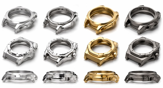
A watch case may pass a basic dimensional check and still fail during assembly, sealing, polishing, or batch production. Thin walls can deform, crown holes can shift, gasket grooves can retain burrs, and finishing can alter critical dimensions. Preventing these failures requires coordinated DFM, datum control, fixtures, machining sequences, inspection, and finish allowances.
Common CNC watch case machining problems include thin-wall deformation, tolerance stack-up, datum shift, incorrect crystal or bezel fits, thread defects, gasket-groove burrs, misaligned side holes, chatter, polishing loss, coating buildup, color inconsistency, and batch variation. Most can be reduced through DFM, staged machining, stable workholding, in-process inspection, and approved finish standards.
The following guide explains how each defect appears, why it happens, how it affects your watch assembly, and what your CNC supplier should control before production begins.
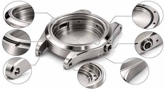
A CNC watch case is both a functional housing and a high-visibility cosmetic component. It must position and protect the movement, electronics, crystal, bezel, case back, crown, buttons, gaskets, sensors, and strap interfaces while maintaining a consistent external appearance.
Many of these features share common datums and functional relationships. The crystal seat may need to remain concentric with the movement cavity. The case-back interface may require controlled flatness relative to a gasket groove. A crown or button hole may meet its diameter tolerance but still fail if its position or axis does not align with the internal mechanism.
The geometry also becomes less rigid as the internal cavity is opened. Cutting force, heat, residual material stress, and fixture pressure can distort the remaining thin walls.
Surface finishing adds another source of variation. Polishing removes material and rounds edges, while anodizing, plating, paint, and PVD alter the surface condition or effective feature size.
For these reasons, a watch case cannot be evaluated only by its outside dimensions. The manufacturing plan must control:
| Problem | Typical Symptom | Likely Cause | Main Preventive Control |
| Thin-wall deformation | Case becomes oval, twisted, or warped after unclamping | Residual stress, uneven stock removal, heat, or excessive clamping | Staged machining, balanced stock removal, and supported fixtures |
| Tolerance stack-up | Individual dimensions pass but the assembly fails | Mating parts and functional chains were not reviewed | DFM and assembly tolerance analysis |
| Datum shift | Crystal, cavity, bezel, and case back are not aligned | Inconsistent locating between machining setups | Functional datums and repeatable fixtures |
| Crystal or bezel fit error | Fit is too tight, loose, tilted, or uneven | Incorrect diameter, depth, profile, or finishing allowance | Precision seat machining and functional inspection |
| Case-back thread defect | Cross-threading, tight spots, or poor engagement | Tool wear, compensation error, burrs, or coating buildup | Thread gauges and post-finish mating checks |
| Gasket-groove defect | Gasket twists, pinches, or lacks compression | Incorrect groove dimensions, burrs, or rough sealing surfaces | Groove inspection and controlled deburring |
| Misaligned holes | Crown, pusher, or spring bar will not assemble | Drill deflection, re-clamping error, or incorrect datum | Multi-axis positioning and true-position inspection |
| Burrs and contamination | Damaged gasket, blocked hole, or difficult assembly | Dull tools, breakout, intersecting holes, or poor cleaning | Toolpath control, deburring, and cleaning |
| Tool marks and chatter | Visible lines, waves, or rough surfaces | Tool wear, vibration, chip recutting, or weak support | Rigid tooling and process monitoring |
| Polishing dimensional loss | Rounded edges, loose fits, or uneven profiles | No polishing allowance or uncontrolled manual finishing | Protected features and approved polishing standards |
| Coating variation | Tight fits, uneven color, rack marks, or blocked holes | Missing allowance, masking, or batch control | Finish samples and post-finish inspection |
| Batch inconsistency | Prototype passes but production varies | Fixture drift, tool wear, finishing variation, or weak revision control | First-article, in-process, and final control plans |
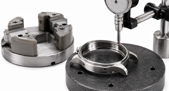
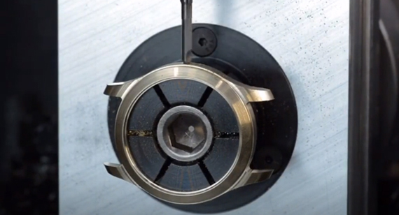
Thin-wall deformation is one of the most serious CNC watch case machining problems because one dimensional change can affect the movement cavity, crystal seat, case back, lugs, and sealing surfaces at the same time.
What Does the Problem Look Like?
A deformed watch case may show:
Why Does It Happen?
Most of the internal material is removed when creating the movement or electronics cavity. As this stock is removed, the remaining case becomes less rigid.
The part can move because of:
Aluminum cases can be particularly sensitive when large cavities leave thin external walls. Stainless steel and titanium can also distort when cutting heat, cutting force, or workholding is not controlled.
How Can It Be Prevented?
A stable manufacturing plan may include:
The correct strategy depends on the material, wall height, cavity depth, unsupported span, and required tolerance.
Tip: Do not reduce wall thickness only to save a small amount of weight. An unnecessarily thin wall can increase fixture complexity, machining time, inspection requirements, and production variation.
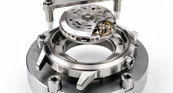
A watch case may meet every isolated dimension shown on the drawing and still fail during final assembly.
This usually happens when individual dimensions have been specified without reviewing the complete functional relationship between the case and its mating components.
Typical Assembly Problems
Common Causes
How Can Assembly Risk Be Reduced?
Before machining, identify the features that directly control:
The supplier should review the 2D drawing, 3D model, mating-component information, surface finish, and assembly method together.
Where necessary, the drawing should use:
Applying a very tight tolerance to every dimension is not an effective substitute for functional tolerance planning. It usually increases machining and inspection cost without guaranteeing assembly.
Note: Dimensional inspection confirms drawing compliance. Trial assembly confirms whether the complete tolerance chain works with the actual mating parts.
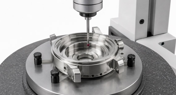
Most watch cases require multiple machining operations. A part may be turned, milled from the front, repositioned for the back, and then located again for the lugs, crown, buttons, engraving, or side openings.
Every repositioning operation creates an opportunity for datum shift.
Features Commonly Affected
Why Does Datum Shift Occur?
Recommended Controls
The process should establish functional datums as early as possible and maintain them through later operations.
Possible controls include:
Three-plus-two-axis or five-axis machining may reduce the number of setups for complex watch cases. However, advanced equipment cannot compensate for unclear datums, weak fixtures, or incomplete tolerance requirements.
For complex integrated lugs and multi-directional openings, link readers naturally to VMT’s 5-axis CNC machining services.
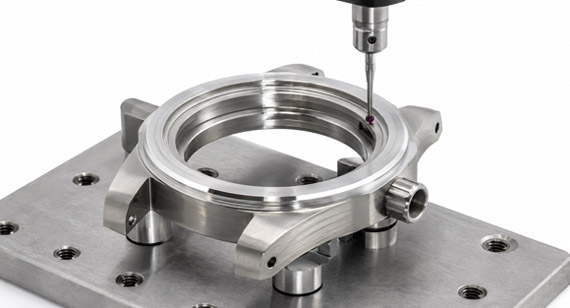
The crystal and bezel interfaces may use a press fit, gasket, adhesive, retaining ring, or another assembly method. Small dimensional errors can therefore cause difficult installation, loose retention, uneven gaps, stress on the crystal, or poor sealing.
Common Symptoms
Critical Characteristics
Depending on the design, the supplier may need to control:
Preventive Controls
The required dimensions should be based on the actual crystal, bezel, gasket, adhesive, and assembly process rather than a generic nominal diameter.
The machining plan should:
A successful fit in one prototype does not guarantee batch repeatability unless the mating components, surface finish, fixture, tools, and inspection standard are also controlled.
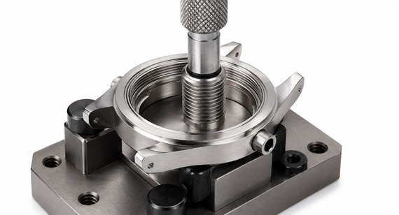
Watch case backs may use threads, screws, snap fits, or other locking structures. Each method introduces different risks related to engagement, alignment, flatness, sealing, and surface finishing.
Typical Problems
Prevention and Inspection
Depending on the case-back design, the supplier may use:
A thread can appear visually acceptable while still having an incorrect pitch diameter, lead, alignment, or engagement. Functional gauging is therefore essential.
Where the case back also forms a sealing interface, its flatness and relationship to the gasket groove should be inspected as one functional system.
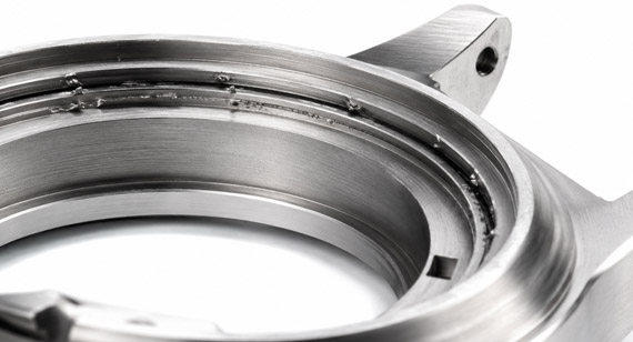
A gasket groove is a small feature with a major influence on assembly and sealing performance.
Typical Problems
Why Do Gasket-Groove Defects Occur?
The groove may require a small, narrow, or extended cutting tool. Such tools are more sensitive to:
The drawing may also omit groove depth, width, radius, roughness, tolerance, or edge-break requirements.
Manual deburring can introduce further variation when too much material is removed from the groove opening.
How Can the Risk Be Controlled?
The drawing should define the groove according to the gasket cross-section and intended compression.
Manufacturing controls may include:
CNC machining can create the dimensions and surface condition required by the design. It cannot independently guarantee water resistance because the completed result also depends on the gasket, crystal, crown, case back, adhesives, lubrication, fasteners, assembly, and pressure or leak testing.
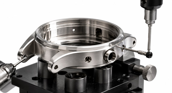
Small holes around the side and back of a watch case are difficult because their position, angle, and relationship to internal components often matter as much as their diameter.
Typical Symptoms
Common Causes
Recommended Controls
Depending on the feature, the machining plan may use:
For paired lug holes, both holes should be evaluated as one aligned feature rather than inspected independently.
Speaker, microphone, and sensor openings also require final cleaning and visual inspection because chips, polishing compound, blasting media, and coating residue can block very small passages.
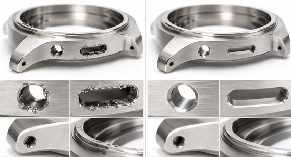
A burr can be too small to notice during a quick visual check but still damage a gasket, interfere with a thread, block a speaker opening, scratch a mating component, or become loose inside an assembled watch.
High-Risk Features
Why Do Burrs Form?
Burr-Prevention Measures
Burr control should begin during toolpath planning rather than relying only on manual cleanup.
The process may include:
Deburring must remove unwanted material without enlarging holes, changing gasket-groove dimensions, weakening threads, or rounding defined cosmetic edges.
Tip: The instruction “break all sharp edges” may be too vague for sealing grooves and close-fitting holes. Define the maximum edge break where the feature affects assembly or sealing.
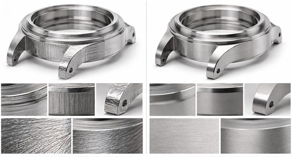
Watch cases contain functional and cosmetic surfaces. A worn tool or unstable process can therefore cause both dimensional drift and visible appearance defects.
Typical Defects
Why Does It Happen?
Stainless steel and titanium can accelerate tool wear and heat generation. Thin aluminum walls may vibrate even when the cutting edge remains sharp.
Recommended Controls
The production plan should define:
Surface finishing should not be used to hide deep chatter or waviness. Blasting may reduce the visibility of light machining lines, while mirror polishing can make waves and toolpath transitions more noticeable.
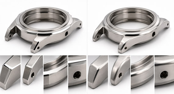
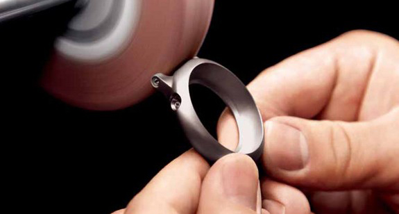
Polishing is not only a cosmetic operation. It removes material and can change dimensions, edges, flatness, and the relationship between adjacent surfaces.
Common Polishing Defects
Common Brushing Defects
Why Does It Happen?
Preventive Controls
The drawing and finishing specification should identify:
A first-off finish sample should be approved before the complete batch enters production.
For more detailed stainless steel grinding, wheel selection, surface preparation, brushing, mirror polishing, cleaning, and inspection, link to the dedicated stainless steel watch case polishing process article. The existing polishing article already covers the general polishing stages and tools, so this page should concentrate on defect prevention rather than repeating that entire process.
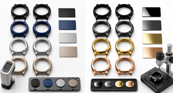
A watch case can meet its machining requirements and then fail after surface finishing because the finish changes the effective feature size, surface condition, or appearance.
Typical Problems
Common Causes
Prevention
Before production, define:
The machining drawing and surface-finishing specification must use the same part revision.
Color should be approved using a physical master sample where batch appearance is commercially important. Screen images and general color names are usually insufficient for controlling actual anodized or PVD appearance.
A supplier may successfully produce one prototype but fail to repeat the same dimensions and appearance across a larger batch.
This often means the prototype relied on manual correction rather than a controlled production process.
Sources of Batch Variation
Handling and Packaging Damage
Finished watch cases can be damaged during:
Common damage includes:
How Can Repeatability Be Improved?
Before batch production, establish:
Finished cases should be individually separated and protected so that approved polished, brushed, anodized, or PVD surfaces do not contact each other during transportation.
Different watch-case materials create different cutting, deformation, burr, finishing, and inspection risks.
| Material | Common Problems | Recommended Controls |
| 6061 aluminum | Thin-wall deformation, scratches, burrs, anodizing variation | Balanced stock removal, supported fixtures, careful handling, approved anodized sample |
| 6063 aluminum | Cosmetic damage, deformation, surface variation | Controlled workholding, protected surfaces, consistent blasting and anodizing |
| 7075 aluminum | Residual-stress movement, edge damage, anodizing color variation | Staged machining, stable stock condition, reduced clamping, finish trials |
| 316L stainless steel | Tool wear, cutting heat, work hardening, burrs, polishing loss | Sharp tools, stable parameters, tool-life control, polishing allowance |
| 904L stainless steel | Greater machining and polishing difficulty | Process trials, rigid tooling, controlled finishing |
| Grade 2 titanium | Burrs, heat concentration, surface damage | Sharp tools, heat control, protected handling, finish validation |
| Grade 5 titanium | Tool wear, chatter, heat, edge damage | Rigid setups, suitable tools, conservative finishing strategy |
| Brass or bronze | Burrs, dents, oxidation, patina variation | Sharp tools, protected handling, controlled cleaning and coating |
Material and surface finish should be selected together. A grade that machines efficiently may not provide the required color, polish, weight, corrosion performance, or batch consistency.
For customers still deciding between billet machining, casting, molding, ceramic, or other production routes, link naturally to the smartwatch case manufacturing methods guide.
A DFM review should be completed before CNC programming, fixture manufacture, and material cutting.
Information Required for DFM
Provide:
Questions the DFM Review Should Resolve
A useful DFM report should identify the risk, explain its effect, and recommend an actionable solution. It should not only state that the component is machinable.
Tip: Separate mandatory design changes from optional cost-saving recommendations. This allows your engineering team to protect functional requirements while evaluating manufacturability and cost.
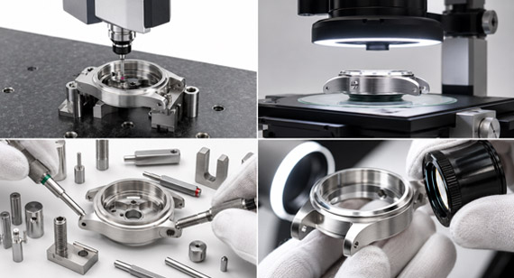
No single measurement method is suitable for every watch-case feature. The inspection method should be selected according to feature size, accessibility, tolerance, surface condition, and functional importance.
| Feature | Main Risk | Possible Inspection Method |
| Movement or electronics cavity | Incorrect fit, position, or wall thickness | CMM, bore gauge, optical system, functional sample |
| Crystal seat | Diameter, depth, profile, and concentricity | CMM, optical measurement, bore gauge, approved crystal |
| Bezel seat | Uneven fit or position | CMM, optical system, functional assembly |
| Case-back face | Flatness and sealing risk | CMM, flatness measurement, mating-case-back check |
| Case-back thread | Engagement and lead-in quality | Thread gauge and approved mating sample |
| Gasket groove | Width, depth, burrs, and position | Optical measurement, profile inspection, magnified visual check |
| Crown and pusher holes | Diameter, position, and axis | Pin gauge, CMM, optical measurement, mating component |
| Spring-bar holes | Alignment and diameter | Pin gauge, optical inspection, strap assembly |
| Surface roughness | Sealing or finishing performance | Surface-roughness tester |
| Polished or brushed surfaces | Scratches, waves, direction, and transition | Controlled-light inspection and approved sample |
| Anodized or PVD surfaces | Color, gloss, rack marks, and coating defects | Approved physical sample and cosmetic inspection |
| Completed case | Overall assembly relationship | Functional trial assembly |
Recommended Inspection Stages
The inspection plan should prioritize features that affect assembly, sealing, appearance, and customer acceptance rather than measuring every dimension with the same frequency.
The lowest initial quotation does not always produce the lowest completed-project cost.
Machining and finishing problems can add cost through:
Drawing Problems That Commonly Increase Cost
Correcting a problem during DFM is usually less expensive than discovering it after machining, polishing, anodizing, PVD, engraving, and assembly.
Tip: Request DFM feedback before approving the quotation. A low price based on an incomplete manufacturing plan may later increase through fixture changes, finishing rejection, inspection sorting, and assembly failure.
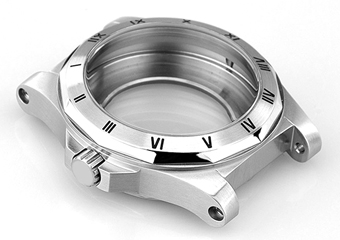
Project Background
A watch-development team required a custom 316L stainless steel case containing:
Project Challenges
During engineering review, several production risks were identified:
VMT Solution
The proposed manufacturing plan included:
Result
The revised prototype could be evaluated for movement fit, crystal installation, case-back engagement, gasket placement, and cosmetic appearance before releasing the pilot batch.
This representative project demonstrates why watch-case quality depends on coordinated drawing review, machining, surface finishing, inspection, and assembly validation rather than final measurement alone.
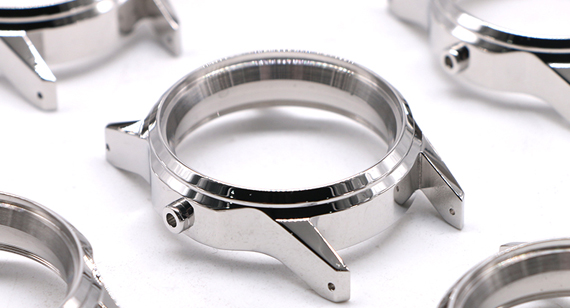
A prototype should validate more than the external shape.
Before production, confirm:
A practical development sequence includes:
VMT’s rapid prototype machining support can be introduced here as the next step for customers who need to validate assembly and appearance before investing in larger quantities.
VMT supports custom watch-case projects through engineering review, prototype machining, fixture planning, multi-axis production, finishing coordination, dimensional inspection, and protective packaging.
Engineering and DFM Review
Before machining, VMT can review:
Fixture and Machining-Sequence Optimization
The workholding and machining sequence can be planned around the case’s functional features to reduce:
Prototype Validation
A functional prototype allows you to test:
In-Process and Final Inspection
Inspection can combine:
Surface-Finishing Coordination
Machining and finishing should be planned as one manufacturing process. Suitable options may include:
VMT’s watch-case service page presents custom watch-case manufacturing for aluminum, stainless steel, titanium, brass, and other materials, together with multi-axis machining, finishing, inspection, prototyping, and production support.
Protective Packaging
Finished cosmetic cases should be individually separated and protected to reduce scratches, dents, contact marks, and coating damage during transportation.
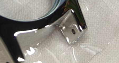
Most CNC watch case machining problems do not begin during final inspection. They begin with incomplete assembly information, unclear datums, unstable wall geometry, unsuitable fixtures, missing finishing allowances, or inspection methods that do not reflect the actual function of the case.
A reliable manufacturing plan should connect your drawings, mating components, material, machining sequence, surface finish, inspection requirements, and packaging before the first production batch begins.
Upload your 2D drawings and 3D models to request a quotation and DFM review. VMT can evaluate thin-wall risks, datum structure, assembly tolerances, gasket grooves, threads, side holes, polishing allowance, coating requirements, inspection methods, and prototype-to-production controls.
Send your CNC watch case drawings for a custom quotation and engineering review.
Send your 2D drawing, 3D model, material, surface finish, mating-component information, inspection report, defect photos, affected quantity and delivery requirements. VMT will review the watch-case risks and provide practical DFM, machining, finishing and inspection recommendations.
All information and uploaded files are secure and confidential.
1 Tell us what you need
2 Get solution & quote
3 Approve production
Email: inquiry@vimetal.com.cn
What is the most common CNC watch case machining problem?
Thin-wall deformation is one of the most common and disruptive problems because it can affect the cavity, crystal seat, case-back flatness, wall thickness, and lug position simultaneously.
It can be reduced through staged machining, balanced material removal, supported fixtures, controlled clamping, and measurement after unclamping.
Why does a watch case pass inspection but fail during assembly?
The individual dimensions may pass while the complete tolerance stack, datum relationship, geometric condition, or post-finishing size is incorrect.
Inspection should evaluate functional relationships and actual mating parts, not only isolated dimensions.
How can movement-cavity deformation be prevented?
Use stable material, balanced rough machining, uniform finishing allowance, supported fixtures, reduced clamping force, controlled cutting heat, intermediate inspection, and final measurement after the case is removed from the fixture.
How do you prevent burrs in gasket grooves?
Use sharp tools, low-runout toolholders, controlled finishing passes, defined tool entry and exit, magnified inspection, and limited deburring that does not change the groove dimensions.
Why does a watch-case thread become tight after finishing?
Anodizing, plating, paint, PVD, polishing residue, or surface damage can change the effective thread fit.
Critical threads may require machining allowance, masking, cleaning, suitable gauges, and final functional inspection after finishing.
Does polishing change watch-case dimensions?
Yes. Polishing removes material and can round edges, reduce local dimensions, change flatness, and weaken the boundary between brushed and polished surfaces.
Critical areas should be protected or machined with an appropriate finishing allowance.
Can CNC machining guarantee that a watch is waterproof?
No. CNC machining can produce accurate gasket grooves and sealing surfaces, but final water resistance also depends on gasket design, adhesives, fasteners, crystal and crown components, assembly procedures, and pressure or leak testing.
How should watch-case concentricity be inspected?
The inspection method depends on the geometry and tolerance. CMM, optical measurement, rotary inspection, gauges, or functional assembly may be used to verify the relationship between the cavity, crystal seat, bezel, and case back.
Is five-axis CNC machining required for every watch case?
No. Simple round cases may be manufactured using CNC turning and three-axis milling.
Three-plus-two-axis or five-axis machining becomes useful for integrated lugs, curved profiles, angled holes, and features requiring several tool directions.
Why do anodized watch cases have different colors between batches?
Color can be influenced by alloy grade, material condition, surface preparation, blasting texture, pretreatment, process parameters, rack position, and batch conditions.
Use consistent material, controlled preparation, and an approved physical color sample.
How can scratches be prevented during production and shipping?
Use clean trays, individual separation, gloves, controlled handling, protected inspection surfaces, suitable films or bags, and packaging that prevents case-to-case contact.
Should every watch-case dimension have a tight tolerance?
No. Tight tolerances should be assigned to dimensions that affect assembly, sealing, alignment, or appearance.
Applying unnecessarily tight tolerances to nonfunctional features increases machining and inspection cost without necessarily improving the finished watch.
What information is needed to diagnose a machining problem?
Provide:
This information helps determine whether the cause is related to design, machining, finishing, inspection, assembly, or handling.


 +86 15099911516




 Read more