16 years one-stop China custom CNC machining parts factory

Hey there I’m VMT Sam!
With 25 years of CNC machining experience we are committed to helping clients overcome 10000 complex part-processing challenges all to contribute to a better life through intelligent manufacturing. Contact us now
 271 |
Published by VMT at May 28 2026 | Reading Time:About 4 minutes
271 |
Published by VMT at May 28 2026 | Reading Time:About 4 minutes


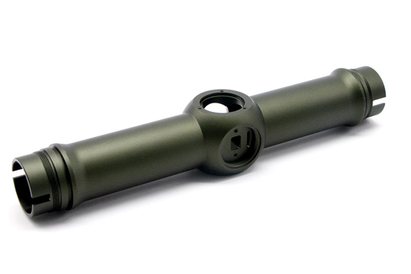
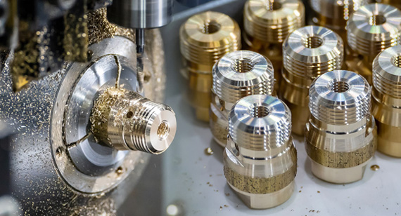
When you hold a high-performance camera lens, you are holding an assembly of multiple glass elements. The optical axis is the imaginary centerline that must run perfectly straight through the exact center of every single lens element, all the way to the image sensor.
If every lens element, the housing bore, and the sensor mount share this exact line with micron-level agreement(datums), the resulting image is sharp corner-to-corner. If they do not, the system suffers from soft edges, one-sided blur, or a tilted focal plane. In this blog, we will dive into the optical axis datum importance, and how to keep datum correct for CNC camera parts, and finally share a case study of how our factory successfully solves this problem for our clients.
In CNC machining, the optical datum acts as the foundation of the entire assembly:
If the datum surface is tilted or offset by just 5 microns during machining, that error compounds as more parts are stacked together. By the time the light reaches the sensor, it can become a 25-micron focal plane tilt. For high-resolution cameras (50MP to 100MP+), a 25-micron tilt is more than enough to ruin image clarity.
In practice, standard CNC shops often treat these critical surfaces like ordinary mechanical holes. As long as the hole diameter is correct and it looks round, they ship it. This misunderstanding is the root cause of massive failure rates during the final optical assembly. How to solve this? It is a must to pay attention to both dimensional precision and geometric precision.
It is not enough to achieve ±5μm dimensional precision, but also to pay attention to geometric precision. Here’ s an example:
A typical CNC shop receives your lens housing drawing. They see a bore with a tight diameter tolerance. They chuck the part, cut the bore, measure the diameter — it’s within spec. They ship it. You assemble the lens. The image is soft on the left side.
Why? Because the bore was cut with the part held on an OD surface that had a 15 μm runout relative to the flange face — which is your real datum. The bore is perfectly round and perfectly sized. But its axis is tilted 15 μm relative to the face that seats against the next component in your optical stack. The CNC shop hit the dimensional tolerance. They missed the geometric one — because your drawing didn’t make the datum relationship explicit.
This is the gap between “CNC precision” and “optical precision.” CNC precision means: I can cut this feature to this number. Optical precision means: this feature’s position and orientation relative to the datum are controlled to sub-micron levels, across multiple setups.

When a lens housing bore must align with the optical datum to within 1 to 2 microns, factories typically choose between two different manufacturing routes. They yield very different results at different price points.
Method A: Mechanical Centering (Alignment Turning)
The part is mounted onto a ultra-precision rotating spindle. An operator or an optical autocollimator checks the baseline surface, manually adjusting the part until any wobble or runout drops near zero (under 1 micron). Once perfectly centered, the lathe machines all internal optical bores and steps in a single setup.
Method B: Adaptive Turning (Error Compensation Machining)
This method uses a standard CNC lathe or mill-turn center. Before cutting, the machine uses a physical touch-probe to measure the part's misalignment. The machine's software then calculates an offset and commands the cutting tool to adjust its path to "compensate" for the error.
Table of Mechanical Centering vs. Error Compensation
| Feature |
Mechanical Centering (Alignment Turning) |
Adaptive Turning (Error Compensation) |
| Centering Accuracy |
<5μm (Excellent) | >5μm (Average) |
| Tilt Control |
Extremely Precise (<0.2arcmin) | Cannot effectively control angular tilt |
| Equipment Required |
Dedicated Optical Alignment Lathe | Standard CNC Lathe / Mill-Turn |
| Per-Part Cost |
High | Relatively Low |
| Best Used For |
Core lens barrels, camera mounts, sensor plates | Outer protective caps, lens hoods, brackets |
The datum you choose on your drawing directly determines how your supplier will fixture the part — and therefore where the errors end up.
Datum Type Matters
The Datum Hierarchy Rule
Your drawing should establish a clear datum precedence:
This A-B-C sequence isn’t just GD&T formalism. It tells the machinist: “Indicate on A first to set the plane, then center on B, then clock on C.” In that order. Every time. That process discipline is what produces repeatable optical alignment.

Here’s how datum errors compound through a real optical assembly. Take a camera with a lens mount flange, a spacer ring, and a sensor PCB.
The Components
The Stack-Up
| Source |
Error Type |
Value (μm) |
| Flange face (Datum A) flatness |
Tilt | ±1.5 |
| Optical bore to Datum A concentricity |
Lateral shift | ±3 |
| Spacer ring parallelism |
Tilt | ±2 |
| Spacer ring thickness tolerance |
Axial shift | ±5 |
| Sensor mount face flatness |
Tilt | ±1.5 |
| Sensor mount to flange perpendicularity |
Tilt | ±3 |
| RSS total lateral error |
~5 μm | |
| RSS total axial error |
~7 μm | |
| RSS total tilt error |
~4.3 μm across sensor diagonal |
For a 24MP APS-C sensor with 3.9 μm pixels, a 4.3 μm focal plane tilt across the diagonal means one corner is more than 1 pixel out of focus. At 100MP on a full-frame sensor with 2.9 μm pixels, that same tilt puts you nearly 1.5 pixels out.
This is why manufacturers of high-resolution cameras — scientific, cinema, surveillance — work with suppliers who understand datum structure. It’s not magic. It’s stack-up arithmetic and process discipline.
Where Can You Tighten?
The spacer ring is the biggest controllable error source. A ground shim can hold ±1 μm parallelism and ±1 μm thickness — but costs 3-5x more than a standard ground ring. The sensor mount perpendicularity is process-dependent: single-setup machining (all features cut without re-chucking) holds ≤3 μm. Multi-setup (part flipped and re-fixtured) typically drifts to 10+ μm.
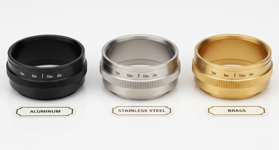
The material you choose affects machinability, stability, and how well it holds a datum over temperature and time.
| Material |
Machinability |
Dimensional Stability |
CTE (10⁻⁶/K) |
Best For |
| 360 Brass |
Excellent | Good | 20.5 | Lens barrels, spacers, shims. Chip breaks cleanly — ideal for small, precise bores. |
| 6061-T6 Aluminum |
Very Good | Good | 23.6 | Housings, flanges, structural mounts. Default for most optical parts. |
| 7075-T6 Aluminum |
Good | Good | 23.6 | High-strength mounts. Harder to anodize consistently. |
| Electroless Nickel on Steel |
Moderate (post-plate machine) | Excellent | 11-13 (steel substrate) | Precision bores requiring wear resistance. NiP can be diamond-turned to <0.1 μm Ra. |
| Invar (FeNi36) |
Difficult | Excellent | 1.2 | Athermalized optical benches. Near-zero CTE. Use when focal plane must not shift with temperature. |
| Titanium (Ti-6Al-4V) |
Difficult | Excellent | 8.6 | Lightweight aerospace optics. CTE matches many optical glasses. Poor thermal conductivity — heat buildup during machining affects datum stability. |
The Heat Problem
Machining generates heat. Heat expands the part. You cut a bore to 50.000 mm. The part cools. The bore is now 49.997 mm — and the datum face has relaxed by 2 μm.
This is why optical datum parts require:
A supplier who measures bores immediately after machining is reporting dimensions that do not represent the part you’ll receive.
When preparing a drawing package for an optical component supplier, verify these five process capabilities to ensure they can hold tight optical tolerances.
1."What is your procedure for establishing the primary datum during setup?"
2."Are all critical optical features machined within a single setup?"
3."What specific metrology equipment do you use to verify geometric alignment?"
4."What is your environmental control and thermal stabilization protocol?"
5."Can you provide a First Article Inspection Report (FAIR) validating all datum-related GD&T callouts?"
This is not optional for optical parts. The FAIR proves they can hit your tolerances on the first run. If they won’t provide one, they’re not confident they can.
The Problem: Lens Mount Alignment Across a Multi-Vendor Supply Chain

A European scientific camera manufacturer approached VMT in 2025. Their product — a cooled CCD astronomy camera — required the sensor plane to be parallel to the lens mount flange within 5 μm across the full sensor diagonal (43 mm). The assembly had three precision-machined parts from three different suppliers:
The Root Cause
When VMT engineers analyzed the drawing package and incoming parts, three failures emerged:
VMT’s Solution
The manufacturer moved all three parts to VMT for single-source production:
The Results

Optical alignment is not a machining tolerance. It’s a process tolerance. The difference: a machining tolerance says “this bore is 50.000 ±0.005 mm.” A process tolerance says “this bore is concentric to the datum face within 2 μm, verified at 20°C, machined in one setup on an indicated fixture.”
Your drawing controls the first while supplier controls the second. Make sure both are right.
VMT machines optical datum parts for scientific imaging, cine lenses, surveillance cameras, and industrial vision systems — from single prototypes to 5,000-unit production runs. Single-setup datum machining. FAIRs on every first article. Thermal-stabilized inspection.
[ Upload your drawing → Get a quote with optical datum review within 24 hours. ]
[ For learning about more comprehensive information about camera lens parts manufacturing, welcome to click and read our technical white paper: The Ultimate Guide to High-Precision Camera Lens Parts Manufacturing. ]

Q1: What is an optical datum in CNC machining?
An optical datum is the reference surface from which all optical alignment features are measured. On a lens housing, it’s typically the flange face (Datum A) and the primary bore (Datum B). The datum establishes the part’s position and orientation during both machining and assembly. If the datum is wrong, every downstream alignment is wrong.
Q2: What accuracy can CNC machining achieve for optical alignment?
Standard CNC with careful fixturing can hold 5-10 μm coaxiality on optical features. Alignment turning (mechanical centering on a dedicated station like TRIOPTICS ATS) achieves <1 μm centering and <0.2 arcmin tilt. The gap is process, not machine capability. A standard CNC with a disciplined operator can hit 3-5 μm. A standard CNC with a standard operator will hit 10-20 μm.
Q3: What is alignment turning and when is it necessary?
Alignment turning lathes the optical surfaces of a part while it is mechanically centered on the optical datum — no software compensation, no re-chucking. It is necessary when the coaxiality requirement is ≤3 μm or the tilt requirement is ≤0.5 arcmin. Typical applications: lens barrels for cinema lenses, prism mounts, interferometer reference housings.
Q4: How do materials affect optical datum stability?
Three factors: CTE (thermal expansion), internal stress relaxation, and machinability. Invar (CTE ~1.2) is the gold standard for athermalized optical benches — it barely moves. 6061-T6 aluminum (CTE 23.6) is stable enough for most applications if machined with stress-relief cycles. Brass (360 alloy) is excellent for small precision bores due to chip control and diamond-turnability. The key rule: rough-machine with coolant, stress-relieve, then finish-machine — regardless of material.
Q5: How do I specify optical datums on a CNC part drawing?
Use GD&T datum callouts with clear precedence: Datum A = primary locating face (flatness tolerance), Datum B = centering bore (concentricity or position tolerance to A), Datum C = clocking feature. Add a note: “Machine Datum A, B, and all optical bore features in a single setup without re-chucking. Dimensions apply at 20°C.” Ask for a First Article Inspection Report covering all datum-related GD&T.
Q6: What’s the biggest mistake designers make with optical part drawings?
Placing the primary datum on a non-functional surface — typically the part OD — instead of the surface that actually locates the part in the optical assembly. The OD is convenient for fixturing but irrelevant to optical performance. If the flange face is what seats against the next optical component, make it Datum A. The bores align to the face, not the OD. Get the datum hierarchy right and half the alignment problems disappear.
The technical information and manufacturing advice shared on the VMT website are for general guidance only. While we strive for accuracy, VMT does not guarantee that the processes, tolerances, or material properties mentioned are applicable to every specific project. Any reliance you place on such information is strictly at your own risk. It is the buyer's responsibility to provide definitive engineering specifications for any production orders. Final specifications and service terms shall be subject to the formal contract or quotation confirmed by both parties.

 +86 15099911516


 Read more