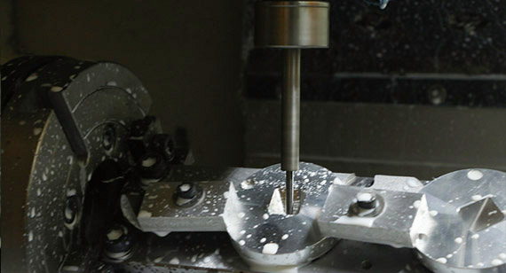
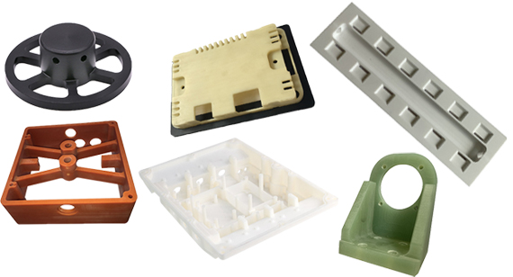
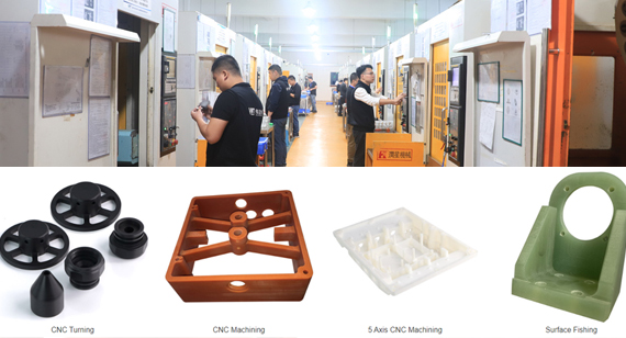
15 years one-stop China custom CNC machining parts factory

Hey there I’m VMT Sam!
With 25 years of CNC machining experience we are committed to helping clients overcome 10000 complex part-processing challenges all to contribute to a better life through intelligent manufacturing. Contact us now
 1456 |
Published by VMT at Oct 31 2023
1456 |
Published by VMT at Oct 31 2023


When we design plastic CNC machining parts, we will inevitably encounter warpage deformation defects.
How to solve warping deformation?
First of all, we must understand the mechanism of warpage deformation, that is, why plastic CNC machining parts warp and deform.
After understanding the basics of the mechanism, we can start from four aspects: plastic materials, plastic parts design, mold structure and molding process, so as to solve it systematically, structured and logically.
Of course, when it comes to warping and deformation of plastic parts, prevention is more important than solving. We must optimize through the above four aspects before warpage deformation actually occurs. Instead of waiting until the warpage deformation actually occurs, then solve it; at this time, it will be very troublesome to solve.

1. Warp deformation can be seen everywhere
Warpage and deformation of plastic parts is one of the most common defects in plastic parts and may occur in any product; at the same time, it is also one of the most difficult defects to solve.

2. Consequences of warping deformation
General warping deformation will cause inconsistent appearance gaps and discontinuities, which will affect the appearance of the product. Consumers may feel that the product grade is too low and give up purchasing.
Severe warping deformation will affect the assembly of the product and even affect the function, performance and reliability of the product.

1. Warping causes inconsistent appearance gaps, seriously affecting the appearance of the product.
2. Warping causes the washing machine’s gripper and glass cover to be weakly bonded.
3. Warpage affects assembly quality, reduces product strength and performance, and has potential risk of failure.
4. The head of the front barrel of the drum washing machine is warped and deformed, causing the gap between the sealing ring and the stainless steel inner barrel to be too small, causing wear and tear on the sealing ring and the stainless steel inner barrel, seriously affecting product reliability.
The root cause of warpage deformation-uneven shrinkage
3.1 Why is the root cause of warpage deformation caused by uneven shrinkage?
The root cause of warping deformation of plastic parts is uneven shrinkage of plastics.

Simulate uneven shrinkage in CAE software
If the plastic part shrinks evenly in all directions during the injection molding process, the size of the plastic part will become smaller at the same time, but it will maintain the correct shape and will not warp.
However, if the shrinkage in any one direction is inconsistent with the other directions, this will cause internal stress. When the internal stress exceeds the strength of the plastic part itself, the plastic part will warp and deform after being ejected.
The left side is the internal stress caused by uneven shrinkage, and the right side is the strength.
3.2 What is shrinkage?
Before understanding uneven shrinkage, we need to understand the shrinkage of plastic materials.
To this end, we need to start with the molecular structure of plastic materials and look at the various changes that occur in plastic materials during the melting and cooling process.
As with most plastic materials, the behavior during melting and cooling depends on the type of plastic material and whether fillers or glass fibers have been added.
1. Amorphous plastic
Amorphous plastics refer to plastics whose molecules are arranged in a disordered state rather than in a crystal structure.
Common amorphous plastics include ABS, PC, PMMA and PPO. Whether in the molten state or in the solid state, the molecular arrangement of amorphous plastics is disordered.
When amorphous plastic melts, the forces between the molecules weaken, allowing the molecules to move toward each other. In addition, the shear force (similar to friction) during the filling stage causes the molecules to unfold and orient themselves in the direction of the solution flow.
When the solution flow stops flowing, the molecules relax and return to their original disordered state. The forces between the molecules push the molecules closer to each other until the temperature is low enough for them to solidify.
These forces cause uniform shrinkage, but relaxation effects cause more shrinkage in the direction of solution flow.

2. Semi-crystalline plastic
Semi-crystalline plastics refer to plastics in which some molecules are arranged in a regular crystal structure in the solid state. This part of the crystal structure is relatively dense and dense. Common semi-crystalline plastics include PBT, PA, POM, PPS and PEEK.
When semi-crystalline plastic melts, the crystalline part loosens and the molecular orientation is consistent with the flow direction of the solution flow, which is roughly the same as amorphous plastic. But when cooled, this part does not relax.
Instead, they remain aligned with the solution flow direction and begin to crystallize, which significantly increases shrinkage. The relaxation effect makes the shrinkage rate in the flow direction of the solution flow much greater than the shrinkage rate in the vertical direction.
Semi-crystalline plastics have a higher shrinkage rate, and semi-crystalline plastics have different shrinkage rates parallel and perpendicular to the direction of melt flow, which complicates the problem. This problem is further complicated by changes in crystallinity caused by changes in injection molding process conditions. If the plastic cools slowly, both crystallinity and shrinkage increase.
3. Glass fiber reinforced plastic
Glass fiber is often added to plastics to increase mechanical strength or other properties. When glass fibers are added to plastics, they may counteract the shrinkage caused by molecular orientation.
When the temperature changes, glass fiber will not expand or shrink. Therefore, in the direction of solution flow, glass fiber will significantly reduce the shrinkage of plastics.
3.2 Why shrinkage is uneven?
What causes uneven shrinkage? There are five main reasons for this.
1. Effect of molecular orientation during filling
At the beginning of filling, shear pressure orients the plastic molecules. When filling stops, the plastic melt is still at high temperature, the shear force disappears, and the orientation relaxes (the orientation will only be maintained when shearing and solidification occur at the same time).
For amorphous plastics, when the orientation is relaxed, the shrinkage is greater parallel to the direction of flow of the solution.
For glass fiber reinforced plastics, the shrinkage is greater in the direction perpendicular to the flow direction of the dissolved material. This is because the molecular orientation of the crystallized part is consistent with the direction of the flow of the dissolved material, and crystallization occurs in the direction perpendicular to the flow direction of the dissolved material.
2. Mold structure limitations
When the plastic part is in the mold, due to the limitations of the mold structure, the plastic part cannot shrink in the plane direction, but it can shrink in the thickness direction.
This has two effects: first, the shrinkage is greater in the thickness direction; second, the residual internal stress is concentrated in the plane direction.
After ejection, since there is no restriction by the mold structure, as the plastic parts continue to cool, stress is released causing warping deformation.
The higher the mold temperature, the slower the cooling rate and the greater the stress release.
The influence of mold structure limitations is affected by plastic materials. Plastic materials with slower stress release have greater linear shrinkage; plastic materials with faster stress release have smaller linear shrinkage.
3. Temperature difference in wall thickness direction
When the mold temperatures on both sides of the plastic part are inconsistent in the thickness direction, the shrinkage on both sides will be uneven.
Generally speaking, the side with higher mold temperature shrinks more, and the side with lower mold temperature shrinks less, which generates a bending moment that causes the plastic part to warp and deform.
4. Uneven wall thickness
When plastic parts have uneven wall thickness, thicker areas require longer cooling times, resulting in greater shrinkage.
5. Uneven pressure holding
Each area inside the plastic part bears uneven pressure holding pressure.
The area near the gate is under high pressure and the area far away from the gate will cool at a different rate, causing uneven shrinkage.
3.3 Four manifestations of uneven shrinkage
Generally speaking, uneven shrinkage mainly manifests itself in four aspects:
1. Different parts of the product shrink unevenly
The plastic parts shrink unevenly in the area close to the gate and the last filled area. The area close to the gate has a small shrinkage, and the area filled last has a large shrinkage.
2. Uneven shrinkage along the thickness direction of the product
If you look at the thickness profile of a plastic part, the shrinkage of the upper and lower areas of the profile is uneven. This inconsistent shrinkage can cause the plastic part to warp because one side shrinks more and the other side shrinks less.
3. Molecular orientation shrinks unevenly in parallel and perpendicular directions
Due to molecular orientation or fiber direction, shrinkage unevenness exists parallel and perpendicular to the flow direction of the plastic part melt flow.
As mentioned earlier, unfilled plastics shrink more in the direction of melt flow, while glass fiber reinforced plastics shrink more in the vertical direction.
4. Uneven shrinkage in the plane direction and thickness direction
Plastic parts usually shrink more in the thickness direction than in the plane direction. This is mainly because there are mold structure restrictions in the plane direction but not in the thickness direction.
This uneven shrinkage can lead to warpage, especially at the corners of plastic parts, where the wall thickness of the part is often greater than the basic wall thickness of the part.
Structured Ideas to Prevent and Solve Warpage Deformation
4.1 Prevention is more important than solution
Warpage deformation of plastic parts must be prevented in advance during the product design stage of plastic parts. You cannot wait until the mold processing is completed and the warpage deformation problem is discovered during the mold trial. It will be too late to solve the problem.
Once the warpage deformation of plastic parts occurs, it is very troublesome to solve. The methods that can be adopted are often few and helpless:
Special or even extreme injection molding process conditions (special mold temperature, high mold temperature difference, long injection molding cycle, etc.);
Modify the mold (modify product design, modify gates, mold counter-compensation, or adopt hot runner), or even re-develop the mold;
plastic surgery jig;
The above methods often require multiple mold trials and debugging to meet the predetermined goals. At the same time, they will also reduce injection molding production efficiency, delay product launch time, and increase product costs.
4.2 Structured ideas to prevent and solve warpage deformation
Preventing and solving warpage deformation problems requires starting from four aspects: material selection, plastic parts design, mold structure and injection molding process.
4.3 Use mold flow analysis software to prevent warpage deformation
It is a very mature and effective method to use mold flow analysis software to accurately predict the warpage deformation trend of the product before opening the mold, and carry out targeted optimization design to reduce warpage deformation.
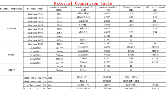
The shrinkage, fluidity, glass fiber content, temperature resistance, etc. of plastic materials all affect the warpage deformation of the product. When other conditions are the same, the warpage deformation of different plastic materials is different.
Semi-crystalline plastics are more prone to warping than amorphous plastics.
Glass fiber reinforced plastics have smaller warpage deformation in the direction of melt flow than non-glass fiber reinforced plastics.
According to the requirements of plastic parts application scenarios, try to use plastic materials with low warpage potential in situations where high dimensional accuracy is required.
Plastic CNC Machining Parts Design
6.1 Uniform Wall Thickness
Uneven wall thickness is a fundamental cause of warpage and deformation of plastic parts. Therefore, when designing plastic parts, it is necessary to follow the principle of uniform wall thickness advocated in the book "Product Design Guidelines for Manufacturing and Assembly".
Where possible, try to make the wall thickness of plastic parts even.

6.2 Smooth Transition at Uneven Wall Thickness
Uneven wall thicknesses require smooth transitions.
6.3 Use Hollowed-Out Designs Where the Wall Thickness is Too Thick
For any place on the plastic part where the wall thickness is too thick, a hollow design must be used to make the wall thickness uniform.

6.4 Try to design a larger draft angle
Try to design a larger demolding angle to avoid warping deformation due to mold sticking during ejection.
General draft angle: 1~2 degrees or more
Minimum draft angle: 0.5 degrees
Functional limit draft angle: 0.25 degrees
Appearance: Increase the draft angle
Biting surface: Depends on the size of the biting surface

6.5 Improve the strength of plastic CNC machining parts
For plastic parts with insufficient structural strength, the strength should be increased by adding reinforcement ribs to avoid deformation due to force during ejection.

6.6 Reasonably design the structure of plastic CNC machining parts
1. L-shaped structure changed to T-shaped

2. Change the T shape to a cross shape

3. When the wall thickness is uneven, the thickness can be kept unchanged and changed to a symmetrical type.
6.7 Correct the warpage of plastic CNC machining parts through assembly design
When warpage deformation of plastic parts is unavoidable, or when the cost of various methods to reduce warpage deformation is too high, plastic CNC parts can be placed in the product structure and the warpage of plastic CNC machining parts can be corrected through the design of other parts.
6.8 Add metal pieces to correct warpage
Warpage can be corrected by adding metal sheets to plastic CNC machining parts, but this method is expensive and is a last resort and is not recommended.
Mold Structure
The three major parts of the mold structure include the pouring system, the cooling system and the ejection system, which have a great impact on the warpage and deformation of plastic parts.
7.1 Reasonable pouring system
The location, structure and number of injection mold gates affect the filling state of plastic in the mold cavity, resulting in warping deformation of plastic parts.
1. Relationship between flow length ratio and warpage
When filling the molten material, the melt flows in the mold cavity. Generally, the temperature of the mold cavity wall is lower than the melting point of the plastic, so the molten material begins to cool from the moment it enters the mold cavity. The solid body forms a non-moving outer shell (condensation layer), while its interior remains a hotter melt (flowing layer).

The longer the flow distance, the greater the internal stress caused by the flow and feeding between the frozen layer and the central flow layer; conversely, the shorter the flow distance, the shorter the flow time from the gate to the flow end of the part, and the frozen layer during filling The thickness is reduced, the internal stress is reduced, and the warpage deformation is greatly reduced.
The longer the flow distance of the melt in the mold cavity, the greater the probability of generating orientation stress. For this reason, for plastic parts with thick walls, long processes, and large areas, several more gates should be appropriately distributed, which can effectively reduce orientation stress and prevent warping deformation. However, many gates are prone to weld marks.
2. Relationship between flow balance and warpage
Filling Pattern refers to the flow situation of molten material that changes with time in the conveying system and mold cavity.
The filling mode has a decisive influence on the warpage of plastic parts. The ideal filling mode is that during the entire filling process, the melt reaches every corner of the mold cavity at the same time at a fixed melt front velocity (MFV); otherwise, The area in the mold cavity that is filled first will overfill and overfill. If the mold cavity is filled with a changing melt wavefront velocity, it will lead to changes in the molecular chain or fiber orientation.
3. Properly design the pouring system
Proper design of the gating system can help reduce warpage and deformation of plastic parts.
1) The gate should be designed when the wall thickness of the plastic part is the largest, which can appropriately reduce the injection pressure, holding pressure and holding time, which is beneficial to reducing orientation stress. When the gate is designed in a thin-walled area, the wall thickness at the gate should be appropriately increased to reduce the orientation stress near the gate.
2) The longer the flow distance of the melt in the mold cavity, the greater the probability of generating orientation stress. For this reason, for plastic parts with thick walls, long processes, and large areas, several more gates should be appropriately distributed, which can effectively reduce orientation stress and prevent warping deformation.
3) Designing a short and thick flow channel can reduce the pressure loss and temperature drop of the melt, correspondingly reduce the injection pressure and cooling speed, thereby reducing the orientation stress and cooling pressure.
4) The runner design should be balanced to ensure balanced glue feeding into each gate. Unreasonable flow channel design will lead to unbalanced material flow filling, and local locations may be overfilled, resulting in large extrusion shear stress, causing stress similar to that caused by excessive holding pressure.
7.2 Proper cooling system
The distribution of cooling water channels should be even, so that the areas near the gate, away from the gate, thick walls, and thin walls can be cooled evenly and slowly, thereby reducing internal stress.
1. Different mold temperatures cause different warping deformations.
When the mold temperatures on both sides of the plastic part are inconsistent, warping and deformation will occur.

2. Optimize cooling water path
By optimizing the cooling water path, all parts of the plastic parts can be cooled simultaneously, thereby reducing warpage and deformation.
Original cooling water circuit design and mold temperature difference
Original cooling waterway design and processing of actual objects and simulations
7.3 Reasonable ejection system
The design of the ejection system also directly affects the warpage deformation of plastic parts. Unbalanced demoulding force, unstable movement of the push-out mechanism, or improper demoulding ejection area can easily cause plastic parts to warp and deform.
To prevent ejection deformation, it is necessary to improve the demoulding conditions: such as balancing the ejection force, carefully polishing the new side, increasing the demoulding angle, and arranging the ejector pin in places with greater demoulding resistance, such as reinforcing ribs and pillars.
7.4 Deformation pre-compensation
Deformation pre-compensation is to apply a certain pre-deformation (reverse deformation) on the structure and size of the corresponding mold parts based on the product deformation predicted by the mold flow analysis software or the actual plastic part deformation during molding to compensate for the deformation during molding. deformation, thereby achieving the purpose of reducing warpage deformation and improving dimensional accuracy.

Injection Molding Process
In order to reduce the warpage deformation of plastic parts, starting from the injection molding process parameters, the following four aspects can be considered:
8.1 Reduce injection pressure and speed
Higher injection pressure and flow rate will produce high shear rates, forming internal stress in the plastic parts, causing the plastic parts to warp and deform.
Smaller injection pressure can reduce the molecular orientation tendency of plastics and reduce its internal stress.
To reduce warpage, the injection pressure and speed are adjusted to the lowest possible range.
8.2 Adjust holding pressure and holding time
If the holding pressure is too high, the flow residual stress solidified due to material replenishment will be high, and the stress will be easily released, causing warping and deformation of the plastic parts.
If the holding pressure is too low, backflow will occur near the gate, which will not only form flow residual shear stress, but also form a large difference in volume shrinkage, resulting in high residual tensile and compressive stress, causing warpage and deformation of plastic parts.
If the holding time is short, backflow will occur near the gate when the screw retreats, resulting in large residual stress.
Therefore, the holding pressure should be moderate, and the holding time should be extended until the gate solidifies, so that the residual stress generated can be smaller.
8.3 Adjust mold temperature
The mold temperature is low and the residual shear stress is large. If there is not enough time to release the residual stress, it is easy to warp and deform. Increasing the mold temperature can reduce warpage.
But it doesn’t just have to be low temperature. For some shapes, low temperature will cause the temperature difference between the mold cavity and the mold core to increase, making it easy to deform. Moreover, when the mold temperature is lower than the ambient temperature of the plastic parts, problems such as deformation or dimensional changes may occur due to post-shrinkage.
Therefore, the most important thing about the mold temperature is not the temperature, but the uniformity (balance) of the temperature including core cooling to achieve uniform shrinkage.
8.4 Adjust cooling time
Because plastic parts retain their shape in the mold cavity for an extended period of time, increasing the cooling time will reduce deformation in many cases.
But for some shapes, the opposite is true. Due to reasons such as the tightness of the mold (mold core), increasing the cooling time may cause poor demoulding and deformation, which cannot be generalized.
Summarize
Warpage and deformation of plastic CNC machining parts has always been a thorny problem.
On the basis of understanding uneven shrinkage and carrying out structured thinking, that is, preventing and solving problems from plastic materials, plastic CNC machining parts design, mold structure and injection molding process, warpage deformation will no longer be a problem.

 +86 15099911516


 Read more