16 years one-stop China custom CNC machining parts factory

Hey there I’m VMT Sam!
With 25 years of CNC machining experience we are committed to helping clients overcome 10000 complex part-processing challenges all to contribute to a better life through intelligent manufacturing. Contact us now
 84 |
Published by VMT at Mar 29 2026 | Reading Time:About 3 minutes
84 |
Published by VMT at Mar 29 2026 | Reading Time:About 3 minutes


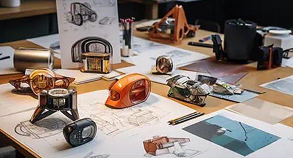
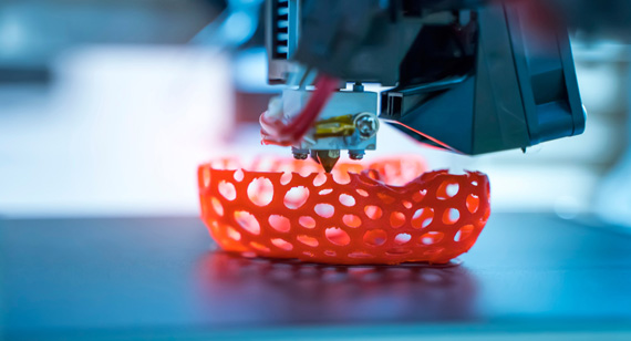
Rapid prototyping is the catalyst for rapid iteration, transforming your 2D or 3D CAD models—from raw materials like plastics, aluminum, steel, and brass—into functional sample parts in record time. This allows you to evaluate critical design factors: Do the tolerances meet your strict assembly or sealing requirements? Does the surface finish and texture align with your brand positioning? Can geometries like fillets or radii be optimized for Design for Manufacturing (DFM) to reduce costs? Once your prototype meets all specifications, it can seamlessly transition into the most efficient manufacturing process for low-volume or mass production.
And this—rapid prototyping—can be realized through:

Table of SLA vs SLS vs FDM vs DMLS: Pros, Cons, and Details of Four Technologies in 3D Printing
| Feature |
SLA (Stereolithography) |
SLS (Selective Laser Sintering) |
FDM (Fused Deposition Modeling) |
DMLS (Metal Powder Bed Fusion) |
| Pros |
Good Surface Finish; Good dimensional accuracy. | No support structures needed; Excellent for Functional Prototypes. | Most cost-effective. | Produces high-strength metal parts with Complex Geometries. |
| Cons |
Parts are brittle. | Grainy surface texture; Porous internal structure; Longer cooling cycles. | Visible layer line. | high cost; Requires extensive Post-processing and support removal. |
| Process & Workflow |
Vat Polymerization: UV laser cures liquid photopolymer resin layer by layer. | Powder Bed Fusion: CO2 laser sinters nylon powder; no supports needed. | Material Extrusion: Thermoplastic filament is melted and extruded through a nozzle. | Metal Powder Bed Fusion: High-power fiber laser melts metal powder in an inert chamber. |
| Common Materials |
Resins: Standard, Tough, Clear, High-Temp, Dental/Medical grade. | Polyamides: Nylon (PA11, PA12), Glass-filled (GF), Flexible TPU. | Thermoplastics: PLA, ABS, PETG, PC, Nylon, ULTEM (PEEK). | Metals: Stainless Steel, Aluminum (AlSi10Mg), Titanium, Inconel. |
| Dimensional Accuracy |
High: ±0.05mm – ±0.1mm. Smoothest surface finish in 3D printing. | Moderate: ±0.1mm – ±0.3mm. Features a slightly grainy texture. | Low: ±0.2mm – ±0.5mm. Visible layer lines (stair-stepping). | High (for Metal): ±0.1mm – ±0.2mm. Near-full density parts. |
| Operational Complexity |
Moderate: Requires handling liquid chemicals and resin filtration. | High: Requires powder management, cooling cycles. | Low: Most user-friendly; "Plug and Play" for simple geometries. | Very High: Specialized safety protocols for reactive powders and gases. |
| Post-Processing & Constraints |
High: Must be washed in IPA and UV-cured. Supports leave marks; parts are brittle. | Low: No support removal. Requires bead blasting or dyeing for aesthetics. | Moderate: Mechanical support removal; Sanding or Vapor smoothing for finish. | Extremely High: Requires EDM to remove from plate; Heat treatment; CNC for finish. |
| Relative Cost (vs. Others) |
Medium: Cheaper than SLS/DMLS, but resins are pricier than FDM filaments. | High: Machines and materials are expensive; best for batch prototyping. | Lowest: Most economical 3D process; significantly cheaper than CNC for 1-10 units. | Highest: Can be 10x-50x more expensive than FDM/SLA; used when CNC is impossible. |
When to Choose 3D Printing for Prototyping?
If you are in the early stages of Research & Development (R&D) and meet any of the following criteria, 3D printing is your optimal solution:
When to Choose 3D Printing for Mass Production?
While 3D printing is traditionally associated with prototyping, it can also utilized for small-batch End-use Parts:
Why did you choose 3D Printing but encounter difficulties when switching to mass production? How to Solve it?
You can encounter difficulties when transitioning from prototypes to high-volume manufacturing due to three core factors:
And for these situations, you may change into manufacturing processes of CNC machining or mold injection.
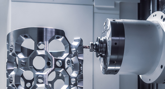
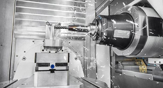
Why CNC Machining is Excellent for Functional Prototypes?

Unlike additive manufacturing( like 3D, is a layer powder after a layer), CNC machining is a subtractive process that carves parts from solid blocks of production-grade material. This ensures the prototype’s mechanical integrity is identical to the final mass-produced part.
If your functional prototypes of your parts with high precision, strength and integrity requirements, and you want to simulate the final shape, size, and functionality; You should choose CNC machining for prototyping because it:
Is CNC Machining Right for Your Prototype?

You should prioritize CNC Machining if your project involves:
Table of CNC machining types, Pros, and Cons
| CNC Machining Type |
Process Overview |
Pros (Strengths) |
Cons (Weaknesses) |
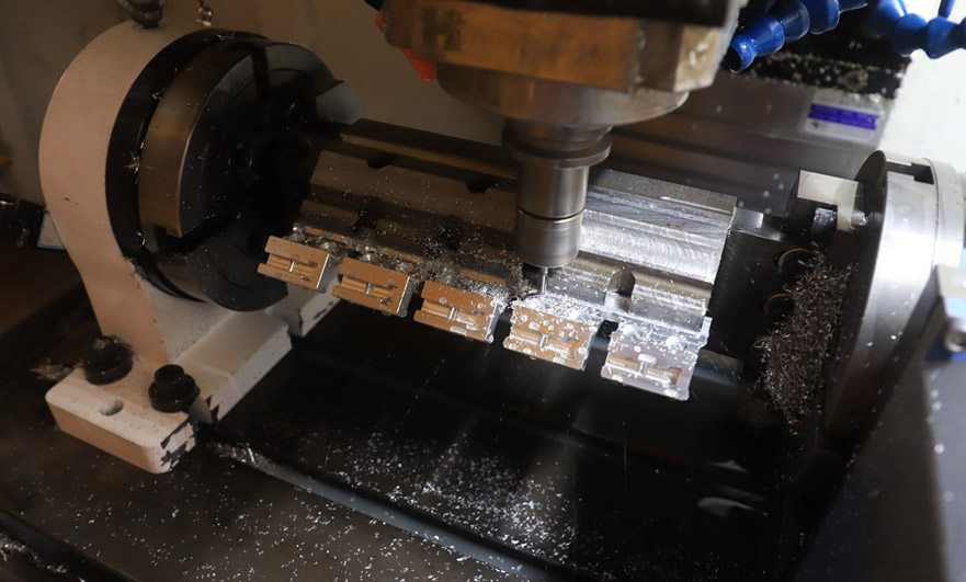
| 3-Axis Milling |
The cutting tool moves along the X, Y, and Z axes while the workpiece remains stationary. | Cost-effective; Widely available; Ideal for simple geometries and flat surfaces. | Multiple setups required for complex parts; Limited to basic 2.5D shapes. |
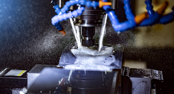
| 5-Axis Milling |
The tool or part moves across 5 different axes simultaneously (X, Y, Z + A, B rotations). | Complex Geometries in a single setup; Superior surface finish; Deep cavity machining; High precision. | High hourly rate; Requires advanced CAM programming and skilled operators. |
| CNC Turning (Lathes) |
The workpiece rotates at high speed while a stationary cutting tool shapes the material. | Fastest production for cylindrical parts (shafts, bolts); Excellent concentricity and surface Ra. | Limited to symmetrical/rotational parts; Not suitable for non-cylindrical features. |
| CNC Turn-Mill |
A hybrid machine that combines a rotating spindle (Lathe) with live milling tools. | Completes Complex Shafts with milled features (flats, holes) in one operation; High accuracy. | More expensive than standard lathes; Limited by the size of the milling attachments. |
| EDM (Wire/Sinker) |
Uses electrical sparks to erode material from conductive metals in a dielectric fluid. | Machining Extremely Hard Metals (Inconel, Hardened Steel); Creates sharp internal corners and thin walls. | Very Slow process; Only works with conductive materials; Higher cost per part. |
| Swiss Machining |
A specialized lathe where the part moves axially while being supported by a guide bush. | Extreme precision for Tiny, Long, or Thin parts (Medical pins, connectors); ±0.005mm accuracy. | High setup costs; Not economical for larger components; Specialized tooling required. |
Rapid Iteration in CNC Machining: Speed vs. Complexity
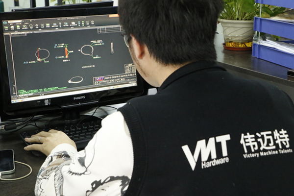
This is benefit from "AI-Driven Path Optimization for CNC Machining" since recent years——
Engineers can now leverage AI-driven CAM software to generate optimal toolpaths faster than ever. These AI-powered systems not only achieve higher precision but also predict tool wear and prevent potential collisions. This helps reduce lead times and minimizes production scrap, ultimately driving down costs while boosting the efficiency and quality of CNC-machined prototypes and low-volume production runs.
So, what does this mean for your prototyping strategy?
As we discussed before, 3D Printing and CNC Machining are ideal for initial Original Concept Validation (1–10 units) for plastic or metal parts, they often become cost-prohibitive as volumes increase. This is where rapid injection molding becomes the suitable one for market pilot launches (50–2,000 units).
For injection molding, it can achieve metal injection molding (MIM); But, rapid prototyping at this stage primarily focuses on engineering plastics (such as PC, ABS, Nylon, and POM) to verify the final small batch of products’ performance.
During the process, rapid tooling(as the cheap mold) is used to validate small-batch prototypes, while formal mold for ten thousands of production is much more expensive.

Table: Process, Pros, and Cons of Rapid Injection Molding
| Feature |
Description |
| The Process |
Molten plastic resin is injected under high pressure into a CNC-machined aluminum or soft-steel mold. This "Rapid Tooling" approach allows for faster mold creation than traditional hardened steel production tools. |
| Pros |
Material Authenticity: Uses the exact production-grade plastics intended for the final product; Cost Efficiency: Significantly lower per-unit cost than CNC for batches over 100; Surface Excellence: Can achieve specific textures (VDI) or high-gloss finishes (SPI) out of the mold. |
| Cons |
Upfront Investment: Requires a "Tooling Cost" for the mold; Design Rigidity: Any design changes after the mold is cut may require expensive and time-consuming modifications; Lead Time: Typically 10–20 days to manufacture the mold. |
| Other vs |
Standard tolerances range from ±0.1mm to ±0.2mm. While less precise than CNC machining, it perfectly replicates mechanical behavior of mass-produced parts. |
When Should You to Transition to Injection Molding?
You should move from your 3D-printed or CNC-machined samples to Injection Molding when:
Sheet metal fabrication is better than 3D printing and CNC machining( only solid components) when you want largely bending or other cold forming the material into enclosures, brackets, and structural chassis etc.; These focuses on cold rolled steel, stainless steel (like 304/316), and aluminum (like 5052/6061) to verify the structural integrity and electromagnetic compatibility (EMC) of the design.
Table: Process, Pros, and Cons of Sheet Metal Fabrication
| Feature |
Description & Technical Specifications |
| The Process |
A multi-stage process involving Laser or Waterjet Cutting of flat sheets, followed by CNC Bending (Press Brake) to form 3D shapes. Final assembly often involves Welding or PEM fastener insertion. |
| Pros |
Unique Thin-Wall Geometry: Capable of producing large-scale, lightweight enclosures that are impossible for CNC or 3D printing; Structural Rigidity: Achieves superior strength through "cold-work" bending rather than material thickness; Material Efficiency: Laser nesting minimizes waste compared to CNC subtractive methods. |
| Cons |
Uniform Thickness Constraint: The design is strictly limited to a constant wall thickness; Geometry Limitations: Cannot produce complex organic curves or variable-thickness features found in molding or 3D printing. |
| Other |
Achieving typical tolerances of ±0.2mm to ±0.5mm for bends and ±0.1mm for laser-cut features. This is sufficient for most industrial enclosures and mounting frames. |
When to Choose Sheet Metal for Your Prototype?
You should transition to a Sheet Metal prototype when your design requirements are:
Hybrid manufacturing with above processes allows you to balance the immediate speed of 3D printing with the high precision of CNC and the scalability of Injection Molding. Here I list the example paths for you:
| Stage |
Process |
Strategy |
| Phase 1: Concept |
3D Printing | Original Creative Validation (1–10 units): Used for rapid form and fit testing. If the 3D-printed sample proves the concept but lacks the required ±0.01mm precision or structural strength, move to Phase 2. |
| Phase 2: Functional |
CNC Machining | High-Precision Verification: Used to verify critical mating surfaces, threads, and mechanical performance. This ensures the part functions perfectly before any capital is committed to molds. |
| Phase 3: Scaling |
Batch Strategy |
Option A (Hundreds of units): If the demand is for 100–500 units and requires high precision, continue with CNC Batch Production. It offers the fastest turnaround without tooling lead times. Option B (Thousands of units): If the 3D/CNC samples are verified and a ±0.1mm to ±0.2mm tolerance is acceptable, transition to Injection Molding to achieve the lowest per-unit cost. |
Choosing the right rapid prototyping process is a balance between speed, precision, and volume. As we have discussed, the goal is to validate your design with the lowest possible risk and cost before moving into mass production. Beyond technical specifications, the success of your prototype depends on selecting a manufacturing partner that offers integrated Quality Assurance (QA) and expert Design for Manufacturing (DFM) feedback. A professional partner should provide more than just a part; they should offer material certifications (COA) and CMM inspection reports to guarantee accuracy, while providing strategic guidance on lead times to ensure your project stays on schedule. Ultimately, navigating the complexities of rapid prototyping is about building a reliable supply chain that can bridge the gap between a high-precision benchtop sample and a field-ready, certified product.


At VMT CNC Machining Factory, we understand that a high-fidelity prototype is the base and first necessary step of successful engineering. With over 17 years of expertise in Rapid CNC Prototype Machining Services, we specialize in transforming complex CAD designs into high-precision metal and plastic components with tolerances as tight as 0.01mm. Whether you are in the initial Original Concept Validation phase or preparing for a Market Pilot, our facility is equipped to deliver industrial-grade quality in as little as 3 to 7 days.
Why Partner with VMT for Your Next Project?
Visit our Rapid Prototyping page to upload your 3D files (STEP/IGS/STL) and receive a professional, transparent quote within 24 hours.

 +86 15099911516


 Read more