15 years one-stop China custom CNC machining parts factory

Hey there I’m VMT Sam!
With 25 years of CNC machining experience we are committed to helping clients overcome 10000 complex part-processing challenges all to contribute to a better life through intelligent manufacturing. Contact us now
 3090 |
Published by VMT at Jun 14 2025 | Reading Time:About 20 minutes
3090 |
Published by VMT at Jun 14 2025 | Reading Time:About 20 minutes


In CNC machining, the language that controls machine movements and operations is essential. Without the right commands, the machining process can be inefficient or even fail.
Yet, many operators find G-code programming to be complex and challenging. Incorrect G-coding can result in costly errors, time delays, and material waste.
This article will explain G-code in CNC machining, demystifying common commands and their uses. Understanding how to utilize G-code efficiently will enhance precision, minimize errors, and optimize production time.
G-code in CNC machining controls the movement of machines. It consists of various commands that guide processes like drilling, turning, and milling. Key commands like G00, G01, and G02 are used to direct rapid movement, linear interpolation, and circular motion. Knowing these commands ensures better efficiency in CNC machining services.
Now that we've established the importance of G-code, let's dive deeper into how it functions within CNC programming. We will explore essential G-code commands and explain their purpose in ensuring accurate and smooth operation in CNC machines.
G-code, also known as Geometric Code, is the language used to control CNC (Computer Numerical Control) machines. It is a standardized programming language that provides specific instructions to a CNC machine, guiding it on how to move, what tools to use, and how to execute various machining tasks such as drilling, turning, milling, or grinding. G-code essentially translates a digital design into physical movement, ensuring precision in the manufacturing process.
Each G-code command tells the CNC machine what to do, such as which direction to move, how fast to go, or when to change tools. For instance, G00 might instruct the machine to move rapidly to a specific location, while G01 directs it to move in a straight line at a controlled speed. These commands are crucial for ensuring that the machine performs tasks accurately and efficiently, transforming a design into a finished part or product.
The G-code system is flexible and works across various CNC machines, including mills, lathes, routers, and grinders, although the specific codes can vary slightly depending on the machine’s make or model. As such, understanding G-code is a fundamental skill for anyone working with CNC machinery, whether in a CNC machining factory or providing CNC machining services.

G-code serves as the "language" that communicates instructions from the operator or programmer to the CNC machine, telling it exactly how to perform various tasks. The commands issued in G-code control the machine’s movements, including positioning, speed, tool selection, and other essential actions. To understand how G-code works, it's important to break down its functionality:
Movement and Positioning:
The most fundamental aspect of G-code is movement control. Commands like G00 and G01 are used to define how the CNC machine should move:
Tool Changes and Control:
CNC machines are typically equipped with multiple tools, such as drills, mills, or lathes. G-code helps manage tool changes, selection, and compensation:
Workpiece Positioning:
G-code also helps establish the machine’s reference point, or origin. The machine’s coordinate system is typically set using commands like G54 (for workpiece offset) and G90 (absolute positioning), where all positions are referenced from a single, defined point.
Cycles and Repetitive Actions:
CNC machining often requires repeating a set of movements, such as drilling or milling specific holes in a pattern. G-code includes canned cycles like G81 (drilling cycle) or G73 (peck drilling), which simplify programming by grouping repeated actions into a single line of code.
Feed Rates and Speeds:
Another crucial element is the control of feed rates and spindle speeds. Commands like F and S control how fast the tool moves through the material (feed rate) and the speed at which the spindle rotates (spindle speed).
Plane and Tool Orientation:
G-code can also specify the plane in which machining occurs. For example:
Program Termination and End:
To mark the end of a program or cycle, G-code includes termination commands such as M02 (end of program) or M30 (program stop and rewind). These tell the CNC machine that the current set of instructions has been completed.
In summary, G-code works by giving the CNC machine precise instructions about how to move, what to do, and when to do it. The machine’s controller reads the G-code line by line, interpreting each command, and performing the corresponding action, resulting in the automated machining of parts.
By understanding how G-code works, CNC operators and programmers can ensure the machine works efficiently, accurately, and safely, producing high-quality parts for a variety of industries.
M-code programming, like G-code, is integral to CNC (Computer Numerical Control) machines, controlling auxiliary functions like tool changes, spindle start/stop, coolant control, and other machine-specific operations. M-codes are typically used in conjunction with G-codes to provide the complete set of instructions required for CNC machining.
Unlike G-code, which is primarily concerned with motion control, M-code governs machine functions that aren't directly related to positioning. The question of who specifically "invented" M-code programming is a bit more complex, as M-codes evolved alongside G-code in the broader context of the development of CNC technology. However, we can trace its origins back to the development of numerical control (NC) and CNC systems in the mid-20th century.

Historical Background
M-codes were developed as part of the Automated Numerical Control (ANC) and later Computer Numerical Control (CNC) systems that emerged during the 1950s and 1960s. The development of both G-code and M-code can be attributed to the early efforts of engineers working in the field of automated manufacturing.
MIT’s Contribution:
The Massachusetts Institute of Technology (MIT) played a crucial role in the development of numerical control systems. In the early 1950s, MIT engineers created one of the first NC systems to control machine tools using punched cards and early computers. This system laid the foundation for both G-codes and M-codes.
The first NC systems included simple commands that could control basic machine functions, and over time, these grew into the more standardized G-code and M-code systems used in modern CNC machines. While G-codes were initially responsible for controlling tool movements, M-codes emerged as the complementary set of commands for non-motion functions.
Machine Tool Manufacturers:
The specific development of M-code programming is not attributed to one individual inventor, but rather to the collective efforts of machine tool manufacturers and engineers who adapted the system to suit the evolving needs of automated machining. Leading companies like Kearney & Trecker, Fadal, Haas Automation, and Fanuc began using and refining M-codes in their CNC machine controls.
Standardization:
As CNC technology became more widespread, various international organizations and associations began standardizing the G-code and M-code systems. One significant effort was by the CNC control manufacturers, who worked together to create standard sets of M-codes for various machine functions, ensuring interoperability across different brands and models.
In summary, M-code programming wasn’t the invention of a single individual but was developed as part of the broader effort to automate machine tool operations through numerical control. It evolved alongside G-code in the mid-20th century, with input from institutions like MIT and various machine tool manufacturers, making it an essential component of CNC machining today.
Reading G-code commands is an essential skill for CNC operators and programmers. G-code, the language that communicates instructions to CNC machines, consists of alphanumeric commands that direct the machine on how to move, what speed to maintain, and which tools to use. Although the G-code syntax may appear complex at first, breaking it down into manageable parts makes it easier to understand. Here’s how to read G-code commands:
1. Understand the G-code Structure
A typical G-code line consists of several elements:
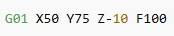
For example, consider the following G-code command:
2. Identify the Key Elements in the Command
Each G-code command typically follows a specific pattern. Let’s break down some common elements you might find in a G-code line:
G Code (Motion Commands):
The G followed by a number represents a specific machine motion or function. For example:
Coordinates (X, Y, Z):
The X, Y, and Z values represent the position of the tool in the machine’s coordinate system. The coordinates define where the tool should move in relation to the origin (zero point). If the coordinate is omitted, the machine will assume it remains at its current position in that axis.
Feed Rate (F):
The F command sets the feed rate, i.e., how fast the tool moves through the material. Feed rates are crucial for controlling the cutting speed and achieving precise machining. For example:
Spindle Speed (S):
The S command sets the spindle speed (RPM) for the tool. It controls the rotational speed of the spindle.
3. Common G-Code Commands to Know
To read G-code efficiently, you should familiarize yourself with the most commonly used G-codes and their meanings. Here are a few examples:
4. Reading M-codes (Machine Functions)
M-codes handle functions that aren’t directly related to motion but control machine operations like starting or stopping the spindle, tool changes, or coolant activation. For example:
5. Understanding Modal vs. Non-Modal Commands
Modal commands remain active until canceled or replaced by another command. For example, if you set G01 for linear motion, the CNC machine will continue moving in a straight line until you change the command to something else, like G02 (circular motion).
Non-modal commands only apply to the current block of code and need to be specified again if they are to be used in subsequent commands. For example, M00 (program stop) is non-modal and will only stop the program when it's executed; it won't stop future movements unless it’s called again.
6. Practical Example
Let’s put together a simple piece of G-code:
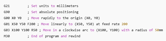
In this example:
Conclusion
Reading G-code requires understanding the structure and purpose of each command. The key is breaking down the commands by their function: G-codes for motion and positioning, M-codes for machine functions, and other elements like feed rates, spindle speed, and tool offsets. As you become more familiar with common G-codes and M-codes, reading and interpreting CNC programs will become more intuitive, helping you operate and troubleshoot CNC machines effectively.
In CNC programming, G-codes are used to direct the movement of a CNC machine and control its operations. Understanding the distinction between modal and non-modal G-codes is crucial for effective programming. This classification helps determine how certain commands behave during the execution of a CNC program. Let’s explore these two categories in detail:
1. Modal G-Codes
Modal G-codes are commands that remain active (or "modal") for the duration of the program or until they are explicitly canceled or replaced by another modal G-code. Essentially, once you issue a modal G-code, its effect will continue until another G-code, either the same or a different one, overrides it. Modal G-codes are useful because they reduce the amount of code needed in a program, improving efficiency and readability.
Examples of Modal G-Codes:
Once a modal command is set, it will remain active throughout the program, and the machine will continue executing the same type of operation unless a new modal G-code is given to modify that operation. For instance, if you use G01 (linear interpolation), the machine will continue to move in a straight line at the programmed feed rate until you switch to another motion command like G02 (circular interpolation).
Why Modal G-Codes are Important:
2. Non-Modal G-Codes
Non-modal G-codes are commands that only apply to the specific line of code where they are used. Once that line has been executed, the effect of the non-modal command ends, and the CNC machine returns to its previous state or settings. In other words, after a non-modal G-code is executed, you must re-specify it in the next line of code if you want the same effect.
Examples of Non-Modal G-Codes:
For example, if you use G04 to make the machine pause for 2 seconds, the pause will only last for that line of code. In the next line, the machine will resume as normal unless you specify another G04 to pause again. Similarly, G28 only returns the machine to the reference point on the line where it’s used—there's no need to cancel it afterward, but the machine will not automatically return to the reference point unless another G28 is called.
Why Non-Modal G-Codes are Important:
3. How Modal and Non-Modal G-Codes Affect CNC Programs
The difference between modal and non-modal G-codes is key to understanding how CNC machines process commands:
4. Examples to Illustrate Modal vs. Non-Modal G-Codes
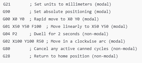
Here’s an example program that uses both modal and non-modal G-codes:
5. Why is the Modal vs. Non-Modal Concept Important?
Conclusion
In summary, modal G-codes are those that remain active throughout the program or until canceled or replaced by another modal code, reducing the need for repetition. Non-modal G-codes, however, apply only to the specific block of code they are used in and must be reissued if their effect is needed again. Understanding the difference between these two types of G-codes is crucial for effective CNC programming and operation.
G-codes play a crucial role in the operation of CNC machines, as they control the movement and behavior of the machine tool. However, the use of G-codes varies depending on the type of CNC machine and the machine's control system. In this section, we'll explore whether all CNC machines use G-codes, what influences their use, and some exceptions.
1. What are G-Codes?
Before diving into whether all CNC machines use G-codes, it's important to briefly define them. G-codes, also known as Geometric Codes, are a set of instructions used in CNC programming to control machine movements. These commands direct the machine to perform specific tasks like moving in a straight line, following a curve, or drilling a hole. They are integral to CNC programming, guiding the machine tool in performing precise movements, feed rates, and actions necessary to create parts.
2. The Use of G-Codes in CNC Machines
Most CNC machines use G-codes to direct motion, control operations, and interact with tooling. Common CNC machines that use G-codes include:
Most modern CNC machines, regardless of the specific type, rely on G-code as the standard method of communication between the operator/programmer and the machine control unit (MCU). The CNC control systems of these machines are often based on ISO 6983 or RS-274D, which are standards that define G-codes and how they should be interpreted.
3. Do All CNC Machines Use G-Codes?
While G-codes are widely used, not all CNC machines rely on them. There are exceptions depending on the machine's purpose, complexity, and control system.
a. Older or Simpler Machines:
Some older CNC machines, particularly those built before the widespread adoption of G-code standards, might not use G-codes in the same way. Instead, they may use custom commands or other programming languages tailored to their specific hardware and capabilities. For example:
b. Machines with Proprietary Controls:
Some machines are designed with proprietary CNC systems that don't use standard G-codes. These machines often feature specialized software for particular tasks, such as laser cutting, water jet cutting, or 3D printing. These systems typically use proprietary programming languages specific to their applications.
For example:
c. CNC Machines with Different Control Systems:
Some CNC machines use control systems that don't rely on traditional G-codes. For instance:
4. When G-Codes are Replaced
Some modern machines and tools have developed their own programming interfaces that may not rely on G-codes. In many cases, these systems are developed to optimize a specific process, such as:
5. Key Takeaways:
Most CNC Machines Use G-Codes: The vast majority of modern CNC machines, including mills, lathes, routers, and grinders, use G-codes for programming. This standardization allows for easy integration, versatility, and communication between different machine types and manufacturers.
6. Conclusion
While G-codes are the universal standard for most CNC machining, not all CNC machines use them. Specialized machines, such as 3D printers, laser cutters, and industrial robots, may employ their own custom programming languages. However, for the vast majority of CNC milling, turning, and grinding machines, G-codes remain the cornerstone of CNC programming. Understanding this distinction is important for anyone working with or programming CNC machines, as it will dictate how a machine is controlled and how you approach the programming process.
G-code is often referred to as the "language" of CNC (Computer Numerical Control) machines, acting as the fundamental set of instructions that guide machine movements and operations. It plays an integral role in CNC machining by providing precise control over the machine tool's actions, ensuring accuracy, efficiency, and consistency throughout the production process. This section will explore the various roles G-code plays in CNC machining, its key functions, and its significance in the overall machining process.
1. Defining Machine Movements
At its core, G-code is responsible for directing the movement of a CNC machine. It defines the tool's path, speed, and direction, guiding the machine to perform specific tasks like milling, turning, drilling, and more. Here's how G-code accomplishes this:
These G-code commands ensure that CNC machines can perform operations ranging from simple cuts to more complex, multidimensional machining tasks. The machine’s ability to follow these specific instructions directly translates into the precise and repeatable production of CNC machining parts.
2. Tool Control and Compensation
Another crucial function of G-code in CNC machining is tool control and compensation. CNC machines use various tools—such as drills, end mills, lathes, and boring tools—each requiring distinct operational parameters. G-codes manage these tools by specifying parameters such as tool offsets, tool changes, and compensation for tool geometry:
These compensations and tool management commands are essential for maintaining machining accuracy, particularly when producing intricate or complex CNC machining parts.
3. Controlling Feed Rates and Speeds
G-code is instrumental in controlling feed rates and spindle speeds, which are critical to the machining process. Feed rate and speed adjustments ensure that the cutting tool moves at an optimal rate for the material being cut, which impacts the surface finish, tool life, and overall machining efficiency:
Proper feed rate and speed control, guided by G-code commands, are crucial for both the speed and quality of the CNC machining process.
4. Establishing Workpiece Coordinates
G-code is also used to define the workpiece coordinate system, which determines the location of the part relative to the CNC machine's tool. This system allows the machine to know the position of the workpiece in 3D space, ensuring accurate machining:
By establishing the correct workpiece coordinates, G-code helps ensure that machining operations occur exactly where they are needed on the workpiece.
5. Automation of Complex Machining Tasks
G-code plays a significant role in automating machining processes, reducing human intervention, and increasing production efficiency. Once the G-code program is written and loaded into the CNC machine, the machine can automatically perform a variety of tasks with high precision and repeatability. This automation is essential for:
6. Safety and Precision
In CNC machining, safety is paramount, especially when working with high-speed machinery. G-codes can include commands to ensure safe operation during machining:
By using G-code commands to control machine safety features, operators can ensure the safety of both the machine and the workers.
7. Flexibility and Versatility
One of the major advantages of G-code in CNC machining is its flexibility. G-code programs can be customized to meet the specific needs of different projects and machines, including:
This adaptability is essential for industries where highly customized parts are needed, such as aerospace, automotive, and medical device manufacturing.
8. Key Takeaways: G-code's Role in CNC Machining
9. Conclusion
G-code is the backbone of CNC programming, playing an essential role in controlling machine movements, tool management, feed rates, and overall machining operations. It ensures that CNC machines produce accurate, high-quality parts with minimal human intervention, making it indispensable for modern manufacturing. Whether for CNC machining parts or complex machining services, G-code helps maintain precision, flexibility, and safety in the machining process.
G-codes, also known as Geometric Codes, are fundamental to the operation of CNC (Computer Numerical Control) machines. These codes provide a standardized set of instructions for guiding CNC machines to perform precise operations. They control everything from the movement of the cutting tool to its speed, ensuring that the machining process is accurate, efficient, and repeatable. In CNC programming, G-codes act as the language that allows operators to interact with the machine in a way that is understandable to both humans and machines.
Here, we’ll explore the importance of G-codes in CNC programming, focusing on their role in achieving high-precision machining, automation, safety, and overall process efficiency.
1. Precision and Accuracy
At the heart of CNC machining is the need for precision. Whether you're manufacturing a simple part or a complex component, achieving high levels of accuracy is essential. G-codes are central to this process because they define the exact movement of the CNC machine tool along various axes.
By guiding the machine’s movements in precise ways, G-codes ensure that CNC machines perform tasks like milling, drilling, and turning with a level of accuracy that is difficult, if not impossible, to achieve manually.
2. Automation and Efficiency
One of the key benefits of CNC machining is the ability to automate repetitive tasks. G-codes provide the foundation for automated machining processes, meaning operators can load a G-code program into a CNC machine and let it run without needing to manually control every movement.
3. Tool Control and Compensation
CNC machines typically work with multiple tools, each designed for different tasks such as drilling, milling, and turning. Tool compensation and management are critical to ensuring that the correct tool is used at the right time and with the appropriate parameters.
By automatically managing tool changes and compensations, G-codes minimize the need for manual adjustments and ensure that all tools perform with consistent accuracy.
4. Safety Considerations
In CNC machining, safety is of paramount importance due to the high speeds at which machines operate. G-codes help integrate various safety protocols into the machine’s operations, reducing the risk of accidents and improving the working environment for operators.
Integrating these safety features through G-code ensures that operators can focus on higher-level tasks without worrying about basic operational errors or hazards.
5. Flexibility Across Different CNC Machines
One of the major advantages of G-code is its universality. Most CNC machines, whether used for milling, turning, drilling, or grinding, rely on G-code as the main programming language. This flexibility allows for the following:
6. Cost Efficiency
G-codes play a crucial role in reducing production costs by optimizing machining time and material usage:
7. Adaptability for Complex Machining Tasks
Some CNC machining tasks require intricate, complex processes that involve multiple steps and varied tool movements. G-code supports this level of complexity by enabling the programming of sophisticated machining tasks:
This adaptability makes G-code essential for industries like aerospace, automotive, and medical devices, where complex part geometries and high precision are often required.
8. Key Takeaways: The Importance of G-Codes
Flexibility and Cost Efficiency: G-code programs can be adapted across different machines and setups, leading to cost savings and higher productivity.
9. Conclusion
G-codes are integral to CNC programming, playing a vital role in automating and controlling the operations of CNC machines. They ensure precise, efficient, and safe machining, making them indispensable in modern manufacturing. Whether used for CNC machining parts or complex CNC machining services, G-codes help optimize processes, reduce errors, and increase production speed, contributing to both productivity and cost savings.
In CNC machining, G-codes (also known as Geometric Codes) form the foundation of the machine's programming language. They dictate the tool's movement, speed, and operation in the machining process. The exact number of G-codes varies depending on the machine's make, model, and the complexity of the operations required. However, there are several core G-codes that are widely used across most CNC machines.
General Overview: G-codes in CNC Machines
Standard G-codes: These are the most commonly used codes that control basic operations like positioning, motion, and cutting.
Common examples include:
Modal G-codes: These G-codes remain active until explicitly canceled or replaced by another code. For example, once G01 is set for linear motion, the CNC machine will continue in a straight line unless a new G-code is specified.
Non-modal G-codes: These codes are active only for a single operation and need to be defined for every line or block of the program where they are used. Once the operation is complete, the G-code is no longer active.
Specialized G-codes: Certain codes are used for specific applications like drilling cycles, thread cutting, or tool compensation. These codes typically control complex functions.
The Total Number of G-codes
The number of G-codes available depends largely on the machine’s capabilities and the manufacturer’s specification. For basic CNC machines, there are around 50–100 core G-codes used for various functions like movement, cycle control, and coordinate system settings. However, for advanced multi-axis CNC machines or those with specific capabilities (e.g., lathe vs. milling), the number may increase significantly.
Key Categories of G-codes
Motion G-codes: These dictate how the tool moves in space, including rapid positioning, linear and circular interpolation.
Plane Selection G-codes: These control the plane in which the tool moves (XY, XZ, YZ planes).
Feed Rate G-codes: These control the feed rate or speed of the cutting tool during the operation.
Coordinate System G-codes: These set the coordinate system used for positioning.
Tool Compensation G-codes: These codes adjust the toolpath for tool diameter, length, or offset adjustments.
Canned Cycle G-codes: These simplify programming for common tasks like drilling, tapping, and boring.
The Total G-codes Count
The total count of G-codes available on most standard CNC machines can range from 50 to 200, but some advanced machines may support up to 300 G-codes, depending on the machine’s complexity and the specific operations it is designed to handle. While the basic G-codes are common across most machines, additional, specialized G-codes may be used by specific CNC machining services or CNC machining factories that require highly customized operations.
Summary
By mastering the most commonly used G-codes, CNC operators can program and optimize the machining process to ensure efficient, precise, and repeatable production of CNC machining parts. For those starting out in CNC programming, it's essential to focus on understanding these core G-codes before diving into more specialized ones.
In CNC machining, G-codes are integral to programming the machine’s movements and functions. These codes provide detailed instructions that control tool paths, feed rates, speeds, and specific machining operations. Below is an overview of some of the commonly used G-codes, especially for lathe operations, highlighting their purpose and usage in the CNC machining process.

CNC Motion and Travel: Command List
G00 – Rapid Movement
G01 – Linear Interpolation
G02 – Circular Interpolation, Clockwise
G03 – Circular Interpolation, Counterclockwise
G04 – Pause
G09 – Exact Stop
G10 – Programmable Data Input
G21 – Input Unit: Millimeters
G22 – Stored Travel Check Function On
G23 – Stored Travel Check Function Off
G27 – Reference Point Return Check
G28 – Return to Reference Position
G32 – Thread Cutting
G40 – Tool Nose Radius Compensation Cancel
G41 – Tool Nose Radius Compensation Left
G42 – Tool Nose Radius Compensation Right
G70 – Finishing Cycle
G71 – Turning Cycle (Roughing)
G72 – Facing Cycle
G73 – Pattern Repeat Cycle
G74 – Pecking Cycle
G75 – Grooving Cycle
G76 – Thread Machining Cycle
G92 – Coordinate System Setting or Spindle Maximum Speed Setting
G94 – Feed per Minute
G95 – Feed per Revolution
G96 – Constant Surface Speed Control
G97 – Constant Surface Speed Control Cancel
Conclusion
The G-codes discussed above are just a few examples of the wide range of codes used in CNC machining for various lathe operations. These commands provide clear, precise instructions to control tool movements, feed rates, and specific machining processes. As a CNC machinist, understanding and using the appropriate G-codes effectively will ensure accurate and efficient production of CNC machining parts.
G-code List (Milling)
In milling operations, G-codes are used to direct the movement of the cutting tool, control machine settings, and manage workpiece coordinates. Below is a list of commonly used G-codes in milling CNC machining. Each code serves a specific function, from tool movements to cycle controls, allowing for precise and efficient machining operations.
CNC Motion and Travel: Command List
G00 – Rapid Traverse
G01 – Linear Interpolation
G02 – Circular Interpolation, Clockwise
G03 – Circular Interpolation, Counterclockwise
G04 – Hold
G17 – XY Plane Selection
G18 – ZX Plane Selection
G19 – YZ Plane Selection
G28 – Return to Reference Position
G30 – Return to 2nd, 3rd, and 4th Reference Points
G40 – Tool Compensation Cancel
G41 – Tool Compensation Left
G42 – Tool Compensation Right
G43 – Tool Length Compensation + Direction
G44 – Tool Length Compensation - Direction
G49 – Tool Length Compensation Cancel
G53 – Machine Coordinate System Selection
G54 – Workpiece Coordinate System 1 Selection
G55 – Workpiece Coordinate System 2 Selection
G56 – Workpiece Coordinate System 3 Selection
G57 – Workpiece Coordinate System 4 Selection
G58 – Workpiece Coordinate System 5 Selection
G59 – Workpiece Coordinate System 6 Selection
G68 – Coordinate Rotation
G69 – Coordinate Rotation Cancellation
G73 – Pecking Cycle
G74 – Left Spiral Cutting Circle
G76 – Fine Boring Cycle
G80 – Fixed Cycle Cancellation
G81 – Drilling Cycle (Point Boring Cycle)
G82 – Drilling or Countersinking Cycle
G83 – Pecking Cycle
G84 – Tapping Cycle
G85 – Boring Cycle (Finish)
G86 – Boring Cycle
G87 – Back Boring Cycle
G88 – Boring Cycle
G89 – Boring Cycle (With Dwell)
G90 – Absolute Command
G91 – Incremental Command
G92 – Workpiece Coordinate System or Spindle Maximum Speed Clamping Setting
G98 – Fixed Cycle Return to Starting Point
G99 – Fixed Cycle Return to R Point
Conclusion
This list of G-codes for milling represents the core set of instructions used in CNC milling operations. These codes enable precise control over tool movement, workpiece positioning, and the execution of specialized machining cycles like drilling, tapping, boring, and cutting. Understanding and using the correct G-codes is essential for efficient and accurate CNC milling.
Here’s a table summarizing the CNC Motion and Travel Command List with their descriptions and uses:
| G-code |
Description |
Use |
| G00 |
Rapid Traverse | Moves the tool to the specified position at maximum speed. |
| G01 |
Linear Interpolation | Moves the tool in a straight line at a defined feed rate. |
| G02 |
Circular Interpolation (Clockwise) | Moves the tool in a clockwise circular path. |
| G03 |
Circular Interpolation (Counterclockwise) | Moves the tool in a counterclockwise circular path. |
| G04 |
Hold | Pauses the program for a set amount of time. |
| G09 |
Exact Stop | Ensures the machine stops precisely at the programmed point. |
| G10 |
Programmable Data Input | Allows for input of data like offsets and coordinates. |
| G21 |
Input Unit: Millimeters | Sets the measurement units to millimeters. |
| G22 |
Stored Travel Check Function On | Activates travel check functions to avoid collisions. |
| G23 |
Stored Travel Check Function Off | Deactivates travel check functions. |
| G27 |
Reference Point Return Check | Checks whether the tool has returned to the reference position. |
| G28 |
Return to Reference Position | Moves the tool back to the reference position. |
| G32 |
Thread Cutting | Used for thread cutting operations. |
| G40 |
Tool Nose Radius Compensation Cancel | Cancels tool compensation for tool radius. |
| G41 |
Tool Nose Radius Compensation Left | Activates tool compensation for the left side of the tool. |
| G42 |
Tool Nose Radius Compensation Right | Activates tool compensation for the right side of the tool. |
| G70 |
Finishing Cycle | Specifies a finishing cycle, typically for turning. |
| G71 |
Turning Cycle | Specifies a rough turning cycle. |
| G72 |
Facing Cycle | Used for facing operations in turning. |
| G73 |
Pattern Repeat Cycle | Repeats the programmed motion in a specified pattern. |
| G74 |
Pecking Cycle | Drills holes by breaking up the cutting into smaller steps. |
| G75 |
Grooving Cycle | Performs grooving operations. |
| G76 |
Thread Machining Cycle | Used for cutting threads on a lathe. |
| G92 |
Workpiece Coordinate System or Spindle Maximum Speed Setting | Sets the coordinate system or spindle speed. |
| G94 |
Feed Per Minute | Specifies the feed rate in millimeters per minute. |
| G95 |
Feed Per Revolution | Specifies the feed rate in millimeters per revolution. |
| G96 |
Constant Surface Speed Control | Maintains constant surface speed during machining. |
| G97 |
Constant Surface Speed Control Cancel | Cancels constant surface speed control. |
This table gives an overview of the key motion and travel commands used in CNC machining, focusing on speed, feed rates, tool movements, and positioning.
Here's a table summarizing the G-code list for CNC milling:
| G-code | Description | Use |
| G00 | Rapid Traverse | Moves the tool to the specified position at maximum speed. |
| G01 | Linear Interpolation | Moves the tool in a straight line at a defined feed rate. |
| G02 | Circular Interpolation (Clockwise) | Moves the tool in a clockwise circular path. |
| G03 | Circular Interpolation (Counterclockwise) | Moves the tool in a counterclockwise circular path. |
| G04 | Hold | Pauses the program for a set amount of time. |
| G17 | XY Plane Selection | Selects the XY plane for circular interpolation. |
| G18 | ZX Plane Selection | Selects the ZX plane for circular interpolation. |
| G19 | YZ Plane Selection | Selects the YZ plane for circular interpolation. |
| G28 | Return to Reference Position | Returns the tool to the machine's reference position. |
| G30 | Return to 2nd, 3rd, and 4th Reference Points | Returns the tool to secondary reference points. |
| G40 | Tool Compensation Cancel | Cancels tool radius compensation. |
| G41 | Tool Compensation Left | Activates tool compensation for the left side of the tool. |
| G42 | Tool Compensation Right | Activates tool compensation for the right side of the tool. |
| G43 | Tool Length Compensation + Direction | Compensates for tool length in the positive direction. |
| G44 | Tool Length Compensation - Direction | Compensates for tool length in the negative direction. |
| G49 | Tool Length Compensation Cancel | Cancels tool length compensation. |
| G53 | Machine Coordinate System Selection | Selects the machine's coordinate system. |
| G54 | Workpiece Coordinate System 1 Selection | Selects the first workpiece coordinate system. |
| G55 |
Workpiece Coordinate System 2 Selection | Selects the second workpiece coordinate system. |
| G56 |
Workpiece Coordinate System 3 Selection | Selects the third workpiece coordinate system. |
| G57 |
Workpiece Coordinate System 4 Selection | Selects the fourth workpiece coordinate system. |
| G58 |
Workpiece Coordinate System 5 Selection | Selects the fifth workpiece coordinate system. |
| G59 |
Workpiece Coordinate System 6 Selection | Selects the sixth workpiece coordinate system. |
| G68 |
Coordinate Rotation | Enables coordinate rotation for toolpath adjustment. |
| G69 |
Coordinate Rotation Cancellation | Cancels the coordinate rotation. |
| G73 |
Pecking Cycle | Performs deep hole drilling in stages with chip breaking. |
| G74 |
Left Spiral Cutting Circle | Performs a left-hand spiral cutting motion (often for threading). |
| G76 |
Fine Boring Cycle | Used for fine boring and threading operations. |
| G80 |
Fixed Cycle Cancellation | Cancels any active canned cycles. |
| G81 |
Drilling Cycle (Point Boring) | Initiates a drilling cycle, including point boring. |
| G82 |
Drilling Cycle or Countersinking Cycle | Drilling cycle with a dwell at the bottom. |
| G83 |
Pecking Cycle (Deep Hole Drilling) | Performs deep hole drilling with tool retraction. |
| G84 |
Tapping Cycle | Performs tapping operations in pre-drilled holes. |
| G85 |
Boring Cycle (Boring without Dwell) | Boring cycle without dwell at the bottom of the hole. |
| G86 |
Boring Cycle with Stop | Performs boring with spindle stop at the hole bottom. |
| G87 |
Back Boring Cycle | Performs back boring for holes with specific tools. |
| G88 |
Boring Cycle (With P Command) | Boring cycle with dwell time, specified by P. |
| G89 |
Back Boring Cycle with Dwell | Performs back boring with dwell at the bottom of the hole. |
| G90 |
Absolute Coordinate Command | Specifies that all coordinates are in absolute mode. |
| G91 |
Incremental Coordinate Command | Specifies that all coordinates are in incremental mode. |
| G92 |
Workpiece Coordinate System or Spindle Speed Setting | Sets the workpiece coordinate system or spindle speed. |
| G98 |
Fixed Cycle Return to Starting Point | Returns tool to the starting point after a fixed cycle. |
| G99 |
Fixed Cycle Return to R Point | Returns tool to the R point after a fixed cycle. |
This table lists the essential G-codes for CNC milling, specifying various functions such as tool movement, compensation, and cycle operations, crucial for precise and controlled CNC milling processes.
In CNC machining, plane selection is crucial to determine the working plane where the tool operates during circular interpolation. G-codes are used to define which plane is being worked on to ensure that the machine moves accurately according to the design specifications. Here are the main plane selection codes used in CNC milling:
| G-code |
Plane |
Description |
| G17 |
XY Plane | This code selects the XY plane for circular interpolation. It is the default plane for most milling operations. |
| G18 |
XZ Plane | This code selects the XZ plane for circular interpolation. It is used for operations where the tool needs to move in the X and Z axes. |
| G19 |
YZ Plane | This code selects the YZ plane for circular interpolation. It is useful for milling operations that involve the Y and Z axes. |
Explanation of Plane Selection
These plane selection codes help control the machine’s movement direction for circular interpolation, ensuring that the tool path corresponds to the correct axis orientation in the CNC system.
In CNC programming, it’s essential to define the units of measurement for the part being machined. G-codes are used to switch between different unit systems, ensuring that the machine interprets the input dimensions correctly. The G20 and G21 codes are used to specify the measurement system—either inches or millimeters—depending on the preferences and requirements of the part design.
| G-code |
Description |
Unit of Measurement |
| G20 |
Inches Mode | Inches |
| G21 |
Millimeters Mode | Millimeters |
Explanation of Dimension Codes
When G20 is selected, the CNC machine operates in inches, interpreting all coordinates, distances, and speeds in imperial units. This is a common setting for machines in countries where imperial measurement systems are used, such as the United States.
Selecting G21 configures the CNC machine to work in millimeters. This is the preferred setting in countries using the metric system, ensuring all measurements are processed in millimeters during the machining process.
Why Dimension Selection is Important
Choosing the correct measurement system is critical for CNC machining to ensure that the machine operates according to the intended dimensions. Incorrect unit selection can lead to significant errors, such as oversized or undersized parts, and could compromise the entire machining process.
When programming, always ensure that the correct G20 or G21 code is set at the beginning of the program to avoid any confusion between units.
In CNC machining, compensation codes (also known as tool offsets) are used to adjust the tool's position based on the geometry of the cutting tool. These codes allow the machine to account for tool wear, tool radius, and length, ensuring accurate part machining. Tool compensation is essential for maintaining consistent machining results, particularly for features like contours, holes, and complex shapes.
Here’s a breakdown of the most commonly used compensation codes:
| G-code | Description | Purpose |
| G40 | Cancel Tool Compensation | Turns off tool compensation and returns the machine to its original tool path without compensation. |
| G41 | Tool Compensation Left | Compensates for the tool radius by moving the tool to the left of the programmed path. Typically used for outside contour machining. |
| G42 | Tool Compensation Right | Compensates for the tool radius by moving the tool to the right of the programmed path. Typically used for inside contour machining. |
| G43 | Tool Length Compensation Positive | Compensates for tool length by adding the tool offset to the tool's position, ensuring the correct cutting depth and height. |
| G49 | Cancel Tool Length Compensation | Cancels tool length compensation, returning the machine to the initial tool position. |
Explanation of Tool Compensation
This code disables any active tool compensation and instructs the machine to follow the programmed path without considering the tool’s radius or offset. It’s commonly used when the tool’s geometry is no longer a concern, or when moving to a different operation requiring a new compensation setting.
When G41 is activated, the CNC machine adjusts the tool’s movement to the left of the programmed path. This is typically used when machining the outer contour of a part. The tool’s radius is compensated for by offsetting the tool to the left to ensure the part’s edge is cut properly.
Similar to G41, but the tool compensates to the right of the programmed path. This is used when machining the inner contours of a part, ensuring that the tool stays on the correct side of the path.
G43 is used to compensate for variations in the length of the tool. It adds the tool length offset to the programmed position to ensure that the tool reaches the correct depth, especially when different tool lengths are used.
This code disables the tool length compensation that was set earlier in the program, returning the machine to its default position without considering any offsets.
Why Tool Compensation is Important
Tool compensation is vital for ensuring accurate machining, especially when dealing with different tool sizes and wear. Without compensation, discrepancies in tool geometry could lead to poor surface finishes, incorrect dimensions, and inefficient operations. By using the appropriate compensation code (G41, G42, G43), CNC machines can account for tool variations, improving the overall precision and consistency of the final product.
In CNC machining, work offsets are used to define the position of the workpiece relative to the machine’s coordinate system. These offsets allow the CNC machine to adjust the zero point (origin) of the part to match the setup or fixture position, which is particularly useful when machining multiple parts or when the part is positioned at an angle or on a fixture. By using work offsets, the machine can ensure that machining operations occur at the correct location on the workpiece.
Here is a table listing the most common work offset codes:
| G-code |
Work Offset |
Description |
| G54 |
Work Offset 1 | The first work offset, typically used for the primary workpiece zero point. |
| G55 |
Work Offset 2 | The second work offset, used for a different workpiece or fixture position. |
| G56 |
Work Offset 3 | The third work offset, used for additional workpiece setups or machine configurations. |
| G57 |
Work Offset 4 | The fourth work offset, similar to G54-G56, for more complex setups. |
| G58 |
Work Offset 5 | The fifth work offset, offering further flexibility in multi-part setups. |
| G59 | Work Offset 6 | The sixth work offset, providing the final option for workpiece or fixture offsets. |
Explanation of Work Offsets
This is the default work offset used when no other offset is selected. It represents the primary workpiece zero point and is commonly used for the first operation or part in a sequence. All coordinates and tool movements are referenced relative to this point.
G55 is typically used when working with a different fixture or workpiece that needs a new origin point. This code is selected when a second part is set up on the machine, allowing the same program to be reused for multiple parts without recalculating positions.
G56 is used in similar situations where a third workpiece setup is required. This allows for more flexibility when machining multiple parts or more complex workpieces with varied fixture placements.
This offset is used in more advanced setups, offering additional flexibility when there are multiple fixtures or complex machining operations involving several workpieces.
Used less frequently than G54 to G57, G58 provides yet another work offset that helps in multi-part or multi-fixture setups. It is beneficial in high-mix, low-volume production runs.
This is the final work offset in the series and is typically used for the most complex setups or when machining several parts simultaneously. Like the others, it allows for precise definition of the part’s position relative to the machine’s coordinate system.
Why Work Offsets are Important
Work offsets are critical for accurate machining, especially in environments where multiple parts are produced or the same part is machined in several stages. They allow the CNC machine to automatically adjust its tool paths to the specific location of each workpiece without the need for manual repositioning or reprogramming. This reduces setup time, enhances accuracy, and improves overall efficiency in the machining process.
By selecting the appropriate work offset, CNC operators can easily switch between different parts or fixtures, reducing the risk of errors and improving the consistency of the parts produced.
Canned cycles are pre-programmed routines that simplify the machining process for common operations. They allow the operator to perform complex tasks, such as drilling, boring, and tapping, by inputting only a few commands. These cycles help reduce programming time and improve consistency, making them essential for various CNC machine operations. Below is a list of commonly used canned cycles in CNC machining:
| G-code |
Cycle |
Description |
| G73 |
High Speed Deep Hole Drilling Cycle | Used for drilling deep holes. Includes chip breaking while drilling to prevent chip clogging. |
| G74 |
Left-Hand Tapping or Deep Hole Drilling | Typically used for face grooving and tapping, also applicable for deep hole drilling. |
| G75 |
CNC Lathe Fast Slotting Cycle | Used for performing fast slotting operations, commonly on CNC lathes. |
| G76 |
Fine Boring Cycle and Threading Cycle | Used for fine boring and threading operations to achieve precise hole diameters and threads. |
| G81 |
Standard Drilling Cycle | The basic drilling cycle, used for drilling holes at specific points or locations. |
| G82 |
Standard Drilling with Dwell at Bottom of Hole | Similar to G81, but includes a dwell time at the bottom of the hole for processes like countersinking. |
| G83 |
Deep Hole Pecking Cycle with Full Hole Retract | Used for deep hole drilling with chip removal during the process. The tool retracts fully after each peck. |
| G84 |
Right-Hand Tapping Cycle | Used to create threads in pre-drilled holes with a right-hand thread. |
| G85 |
Reaming or Boring Cycle | Performs reaming or boring, used for enlarging holes with precision. |
| G86 |
Drill and Stop Cycle | The spindle stops when the tool reaches the bottom of the hole. Used for specific, controlled operations. |
| G87 |
Boring Cycle with Special Tool to Enlarge Hole | Used to enlarge the hole diameter with specialized tools, typically for finishing operations. |
| G88 |
Boring Cycle with P Command (Dwell Time) | A boring cycle that allows a specified dwell time at the bottom of the hole (P command). |
| G89 |
Back Boring Cycle with Dwell | Performs back boring with a dwell at the bottom of the hole, used for more precise hole finishing. |
Explanation of Canned Cycles
G73 is designed for drilling deep holes efficiently. The cycle includes chip breaking to ensure smooth chip removal, especially in deep drilling operations. This cycle helps prevent issues like chip clogging or heat buildup.
G74 is primarily used for tapping operations but can also be used for deep hole drilling. It’s typically employed for tapping with a left-hand thread, but its versatility makes it useful for face grooving or other drilling operations that require a left-hand motion.
This canned cycle is used for slotting operations on CNC lathes. The cycle optimizes the cutting process for fast and efficient slot creation.
This cycle is typically used for fine boring operations that require tight tolerances, as well as for threading operations. The G76 cycle is often applied in operations requiring precision, such as internal threading.
G81 is the most common drilling cycle used in CNC machining. It’s used to drill holes at specific locations, with the machine automatically handling the movement and positioning of the tool.
Similar to G81, but with a dwell feature at the bottom of the hole. This is especially useful for countersinking, where the tool stays at the bottom for a few seconds to achieve a clean, accurate finish.
G83 is used for drilling deep holes while retracting the tool after each “peck” to clear chips. This cycle is essential for drilling deep holes in tough materials, ensuring efficient chip removal.
G84 is used for creating threads in pre-drilled holes with right-hand threads. The cycle ensures precise, consistent threading operations, making it ideal for various tapping applications.
This cycle is used for enlarging holes with high accuracy. It’s typically employed after drilling to ensure that the hole has the desired diameter and smooth surface finish.
This cycle causes the spindle to stop once the tool reaches the bottom of the hole. It’s often used for operations that require controlled hole depth and stoppage at the hole’s bottom, such as for blind holes or specific reaming operations.
G87 is used for boring holes with a special tool, such as an expandable or adjustable reamer, to enlarge or finish the hole diameter with higher precision.
This cycle allows the user to specify a dwell time (P command) at the bottom of the hole. This can be useful in processes that require a pause for further operations like deburring, cleaning, or cooling.
G89 is used for back boring, which involves enlarging a hole from the opposite side of the part. The cycle includes a dwell time at the bottom of the hole for finishing, providing a precise hole diameter.
Why Canned Cycles Are Important
Canned cycles greatly reduce programming time and complexity. By using these pre-programmed commands, CNC operators can avoid writing out lengthy code for each operation, allowing for quicker setup and easier programming, especially for common operations like drilling and tapping. This increases efficiency, reduces errors, and ensures the machine operates smoothly and accurately, making canned cycles essential in modern CNC machining.
Cancel codes are commands used in CNC programming to stop or cancel certain functions, cycles, or settings that were previously activated. They help return the machine to its default state, ensuring that further operations are not affected by any previously set parameters. Below are some important cancel codes:
| G-code |
Function |
Description |
| G50 |
Scaling / Absolute Zero or Spindle Speed Limit | Used to cancel any scaling factor, reset the zero center point in some machines, or set spindle speed limits. |
| G80 |
Cancel All Active Fixed Cycles | Cancels all currently active canned cycles, such as drilling or tapping cycles, returning the machine to normal mode. |
Explanation of Cancel Codes
G50 is used to cancel any scaling settings in the CNC program. This command can also be used in some CNC machines to reset the absolute zero center point or to set spindle speed limits to prevent the machine from exceeding safe operational speeds. After setting a scaling factor or adjusting spindle speed limits, this command ensures that those settings do not affect the subsequent machining operations.
G80 is used to cancel all active fixed or canned cycles in CNC programming. When a fixed cycle like drilling or tapping is no longer needed, G80 is called to stop the cycle and reset the machine to its normal state. This prevents the CNC machine from continuing any pre-programmed operations, ensuring the process is correctly halted before moving on to the next task.
Importance of Cancel Codes
Cancel codes are essential for controlling the flow of operations in CNC machining. They allow operators to terminate specific functions or cycles that may no longer be required, providing greater flexibility and control over the machining process. By using G50 and G80 appropriately, operators ensure that the machine can quickly adapt to new tasks, avoid unwanted behaviors, and operate safely.
Positioning modes in CNC machining determine how the machine interprets and moves along its axes. The two main types of positioning modes used are absolute mode (G90) and incremental mode (G91). Understanding the difference between these modes is crucial for precision control and accurate machining.
| G-code |
Function |
Description |
| G90 |
Absolute Positioning Mode | Moves are based on a fixed point of reference, usually the machine's zero point. |
| G91 |
Incremental Positioning Mode | Moves are based on the current position of the tool as the reference point. |
Explanation of Positioning Modes
In absolute mode, the CNC machine moves to positions based on a fixed origin point (often the machine’s home or zero point). For example, if you program the machine to move to a position at X=50, Y=50, the machine will always move to this absolute position relative to the zero point, regardless of its current location. This mode is ideal for operations that require precise control over the position relative to a fixed reference.
In incremental mode, the CNC machine moves relative to its current position. For instance, if the machine is at X=50, Y=50 and you command it to move by X+10, it will move 10 units from its current location, making the new position X=60, Y=50. This mode is useful when making repetitive movements or for tasks that require small, relative adjustments.
Importance of Positioning Modes
Choosing the correct positioning mode is critical for the desired machining outcome. Absolute positioning (G90) offers a predictable, fixed reference that is ideal for tasks requiring accuracy based on a known starting point. On the other hand, incremental positioning (G91) is flexible, making it easier to adjust movements relative to the tool’s current location, which can be more efficient for certain tasks. Understanding how these modes work ensures that operators can precisely control the toolpath and avoid errors in CNC machining.
In CNC machining, speeds and feeds refer to the rate at which the tool moves through the material and the speed at which the spindle turns. These parameters directly affect the quality, efficiency, and lifespan of both the tool and the workpiece. The G-codes governing these settings help ensure optimal cutting conditions and performance. Below are some of the key G-codes related to speeds and feeds in CNC machining.
| G-code |
Function |
Description |
| G94 |
Feed per Minute Mode | Defines the feed rate (how fast the tool moves) in units per minute. |
| G95 |
Feed per Revolution Mode | Defines the feed rate in units per spindle revolution. |
| G96 |
Constant Surface Speed | Maintains a constant cutting surface speed, adjusting spindle speed as needed. |
| G97 | Constant Spindle Speed | Fixes the spindle speed at a constant value, regardless of cutting conditions. |
Explanation of Speeds and Feeds Codes
In feed per minute mode (G94), the CNC machine moves the tool at a constant rate, measured in units of distance per minute (typically inches or millimeters). This mode is commonly used for linear movements where the operator needs to set a consistent feed rate to achieve the desired surface finish or cutting conditions. For example, if you specify a feed rate of 100 mm/min, the machine will move the tool at that rate across the entire machining path.
In feed per revolution mode (G95), the feed rate is defined by how far the tool moves relative to each spindle revolution. This mode is particularly useful for turning operations, where the tool follows the rotating workpiece, and the feed rate depends on the number of revolutions per minute (RPM) of the spindle. It ensures that the tool maintains consistent cutting depth regardless of the spindle speed.
Constant surface speed (G96) ensures that the cutting speed remains constant along the surface of the workpiece, regardless of the diameter. As the tool moves along the workpiece, the CNC machine adjusts the spindle speed to maintain a constant surface speed. This is critical in turning operations to ensure optimal cutting conditions and prevent tool wear due to varying cutting speeds, especially in the case of larger diameter workpieces.
Constant spindle speed (G97) locks the spindle speed at a fixed RPM, ensuring that it does not change during the operation. This is ideal when you want to maintain a specific cutting speed regardless of changes in the tool or workpiece diameter, often used for milling and drilling operations where the cutting conditions do not require adjustments to the spindle speed.
Importance of Speeds and Feeds Codes
Properly setting speeds and feeds is vital for efficient CNC machining. Using G94 and G95 allows for precise control over the tool movement, improving the accuracy of cuts and extending tool life. G96 ensures that the tool operates under optimal conditions, adapting spindle speed to maintain constant surface speed. Meanwhile, G97 provides stability in situations where constant spindle speed is required. Choosing the right mode for the job ensures the machine operates efficiently, delivering high-quality results with minimal tool wear and machine strain.
In CNC machining, plane return commands are essential for controlling the position of the tool when transitioning between various movements, especially in repetitive operations. These G-codes help ensure that the tool moves back to a specific reference plane or position after completing a machining task, which is crucial for safety, accuracy, and efficiency.
| G-code |
Function |
Description |
| G98 |
Return to Initial Plane | Returns the tool to the starting point (initial plane) after completing a cycle. |
| G99 |
Return to Rapid Plane | Returns the tool to a predefined rapid traverse position after completing a cycle. |
Explanation of Plane Return Codes
The G98 command instructs the CNC machine to return the tool to its initial plane after finishing a cycle. This is typically used in drilling or tapping cycles where the tool must return to the starting point at a specific elevation above the workpiece before performing another action. It ensures that the tool maintains a safe distance from the part during transitions, avoiding accidental collisions.
For example, if a drilling operation is completed and G98 is used, the tool will retract back to the Z-axis position that was originally set at the start of the cycle (often above the part surface), ready for the next operation or cycle.
The G99 command is used to return the tool to a rapid traverse position (or "safe height") after completing a cycle. Unlike G98, which returns the tool to the initial plane, G99 returns the tool to a predefined "rapid" height that is safe and above the part. This allows for faster tool movements during transitions, as the tool doesn't need to return to the exact initial starting point.
In many cases, G99 is preferred when you need the tool to clear the workpiece rapidly, especially after drilling or tapping operations, and when it's unnecessary to return to the exact initial plane.
Importance of Plane Return Codes
By choosing the right return mode, the CNC operator can manage the tool's retraction behavior effectively, ensuring both safety and efficiency in the machining process.
While G-codes like G00 for rapid movement and G01 for linear interpolation are widely used in CNC machining, there are many other less common G-codes that serve specialized purposes. These codes are essential for specific functions such as offsets, macro programming, and advanced machine movements. Understanding these lesser-known G-codes can improve machining precision and enhance the versatility of the CNC machine.
| G-code |
Function |
Description |
| G10 |
Programmed Offset Input | Allows for the input of offset values into the CNC program, which can adjust tool positions or other parameters dynamically. |
| G22 |
Stored Travel Limit | Activates stored travel limits, restricting the movement of the tool to predefined boundaries. |
| G23 |
Stored Travel Limit Cancel | Cancels the stored travel limits set by G22, restoring normal tool movement. |
| G27 |
Zero Return Check | Verifies if the machine is at its reference position (machine zero). This can be used for safety checks. |
| G28 |
Zero Point Return | Returns the machine tool to its home or reference point, often used to ensure the tool is in a known position. |
| G29 |
Return from Reference Position | Returns the tool to a position relative to the reference point (commonly used in conjunction with G28). |
| G30 |
Second Position Zero Point Return | Returns the tool to the second zero point position, which is useful for secondary operations or tool changes. |
| G31 |
Skip Function | Allows the machine to skip a portion of the program based on a specific condition, commonly used in probing operations. |
| G44 |
Negative Tool Length Compensation | Applies negative tool length compensation, adjusting for tool length variations. |
| G45 |
Single Offset Increase | Increases the current offset value by a specified amount, used for fine adjustments. |
| G46 |
Single Offset Decrease | Decreases the current offset value by a specified amount. |
| G47 |
Double Offset Increase | Increases the current offset value by double the specified amount. |
| G48 |
Double Offset Decrease | Decreases the current offset value by double the specified amount. |
| G51 |
Scaling | Scales the part program by a specified factor, allowing for resizing without modifying the geometry. |
| G52 |
Temporarily Shift Program Zero | Temporarily shifts the program's zero reference, useful for operations involving multiple setups. |
| G53 |
Return to Machine Zero Position | Moves the tool back to the machine's absolute zero point, typically used for safety or after completing a cycle. |
| G60 |
One-Way Movement | Restricts the movement of the tool to a one-way path, often used for specific operations like reaming or tapping. |
| G61 |
Exact Stop Check (Modal) | Forces the machine to stop at each position before moving to the next, ensuring precise positioning. |
| G64 |
Normal Cutting Mode | Allows continuous cutting mode, where the machine moves between points without stopping at each one. |
| G65 |
Custom Macro Call | Calls a custom macro subroutine, allowing for more complex and reusable operations. |
| G66 |
Custom Macro Modal Call | Similar to G65, but the macro is called in a modal manner, staying active until explicitly canceled. |
| G67 |
Cancel Custom Macro Modal Call | Cancels the modal custom macro call initiated by G66. |
| G68 |
Coordinate Rotation Mode | Activates coordinate rotation, which allows for rotating the entire coordinate system during machining operations. |
| G69 |
Cancel Coordinate Rotation Mode | Cancels the coordinate rotation set by G68, returning to the standard coordinate system. |
| G92 |
Program Work Offset | Sets a custom work offset, often used to establish a specific part coordinate system or to zero out the machine during a program. |
Explanation of Less Commonly Used G-Codes
This G-code allows the user to input specific offset values, which can be applied dynamically during machining. It is useful when tool offsets or other parameters need to be adjusted mid-process without manually altering the program.
These codes help restrict the machine’s movements to a predefined area. G22 sets the limits, while G23 cancels them, ensuring the machine doesn’t exceed certain boundaries and preventing damage to the workpiece or tooling.
A safety check command, G27 verifies whether the machine has returned to its reference position. This is an essential step in ensuring that the machine is in a safe position before beginning a new cycle or task.
These G-codes control the tool’s return to the home position (machine zero), ensuring the machine starts a new task from a known and safe position. G29 works in conjunction with G28, allowing the machine to return from its reference position to a predetermined location.
This G-code limits the tool’s movement to a single direction, which is especially useful for operations like tapping or reaming where the tool needs to follow a precise, one-way path.
G61 ensures the machine stops at each position, providing precision for intricate operations. G64, on the other hand, allows for continuous movement between points, which is ideal for standard cutting operations where high precision is less critical.
These commands enable advanced users to program custom subroutines, creating reusable and efficient operations for complex or repetitive tasks. G66 keeps the macro active until explicitly canceled, while G65 only calls the macro once.
G92 is typically used to set a specific work offset, which is particularly useful in multi-step operations or when setting up a machine with non-standard workpiece locations. It establishes a custom coordinate system for the part being machined.
Importance of Less Common G-Codes
These less commonly used G-codes are crucial for specialized tasks, offering advanced capabilities that allow operators to fine-tune their CNC programs for more complex or precise operations.
Yes, when writing G-code for CNC machines, safety is paramount. Improperly written G-code can lead to accidents, machine damage, or even injury to operators. Here are some important safety issues to consider:
1. Machine Home Position (Zero Reference)
2. Collision Prevention
Solution:
3. Tool Length Offsets and Compensation
Issue: Incorrect tool offsets or tool length compensation (G43) can lead to a tool cutting too deep or not deep enough into the workpiece.
Solution:
4. Spindle Speed and Feed Rate
Issue: Incorrect spindle speeds (G96, G97) or feed rates (G94, G95) can lead to damage to both the tool and workpiece, such as excessive heat buildup or tool breakage.
Solution:
5. Inappropriate Use of Canned Cycles
Issue: Misuse or lack of understanding of canned cycles (e.g., G81, G83) can result in incorrect drilling, tapping, or boring operations, which can cause part damage or tool failure.
Solution:
For deeper drilling cycles (e.g., G83), be sure to account for chip removal and tool wear, which could impact cycle performance.
6. Tool Change Safety
Issue: Automatic tool changes can be dangerous if the tool holder is not properly aligned or if the tool is not secure.
Solution:
7. Spindle Direction and Tool Rotation
Issue: Incorrect spindle direction settings (G02 for clockwise and G03 for counterclockwise) or incorrect tool rotation can result in machining errors, poor surface finish, or tool damage.
Solution:
8. Inaccurate Work Offsets
Issue: Incorrect work offsets (G54-G59) can cause the tool to operate at the wrong location relative to the workpiece, leading to collisions or incorrect machining.
Solution:
9. Use of Rapid Movements (G00)
Issue: G00 (rapid movement) can be dangerous if used too aggressively or inappropriately, as the tool moves at maximum speed and could collide with obstacles.
Solution:
10. Power Failures and Program Resumption
Issue: Power failures or interruptions during machining can lead to the loss of program data or misalignment when resuming the program.
Solution:
11. Contingency for Errors
Issue: Sometimes, unexpected errors in the G-code or machine behavior could lead to dangerous outcomes.
Solution:
12. Emergency Stop (M00/M01)
Issue: If an emergency occurs during machining (e.g., tool breakage, unexpected behavior), the program might not automatically stop.
Solution:
Summary
When writing G-code for CNC machining, safety is a critical factor. By ensuring the proper use of machine home positions, tool offsets, spindle speeds, work offsets, and the correct application of commands like G00, G01, G28, and M00, you can prevent collisions, machine damage, and operator injury. Proper planning and testing of G-code, along with the use of safe programming practices and machine settings, are essential for a safe and efficient CNC machining environment.
Here’s a table summarizing the Safety Issues and Solutions in writing G-code for CNC machines:
| Safety Issue |
Description |
Solution |
| Machine Home Position (Zero Reference) |
Improperly setting the home position can cause collisions with parts, fixtures, or other components. |
Use G28 (return to machine home) and G30 (second home position) to return the tool to a safe position. |
| Collision Prevention |
Incorrect toolpath programming can lead to tool and part collisions. |
Verify toolpath with dry runs or simulation. Use G00 (rapid traverse) carefully. |
| Tool Length Offsets and Compensation |
Incorrect tool offsets or tool length compensation can lead to improper depth or tool damage. |
Double-check tool offsets. Use G43 (tool length compensation) carefully and G40 (tool compensation cancel). |
| Spindle Speed and Feed Rate |
Incorrect spindle speeds and feed rates can damage the tool or workpiece. |
Set correct speeds and feeds. Use G94 (feed per minute) or G95 (feed per revolution) based on the operation. |
| Inappropriate Use of Canned Cycles |
Misuse of canned cycles (e.g., G81, G83) can cause incorrect operations, leading to part or tool damage. |
Verify depths and retract positions for canned cycles. Use G80 to cancel active cycles. |
| Tool Change Safety |
Automatic tool changes can cause tool misalignment or crashes. |
Test tool change routines. Set proper clearances for tool changes to avoid collisions. |
| Spindle Direction and Tool Rotation |
Incorrect spindle direction or tool rotation can lead to machining errors. |
Double-check spindle direction commands like G02 (clockwise) and G03 (counterclockwise). |
| Inaccurate Work Offsets |
Incorrect work offsets (G54-G59) can cause the tool to operate at the wrong location. |
Set and verify work offsets at the beginning of the program. Ensure the correct offset is selected during operations. |
| Rapid Movements (G00) |
Using G00 can cause the tool to move too fast, possibly resulting in a collision. |
Use G00 for safe rapid movements, but switch to G01 in tight spaces for controlled, slower movements. |
| Power Failures and Program Resumption |
Loss of power can lead to misalignment or loss of program data. |
Use G27 (zero return check) or G28 (return to home) for safe positioning during power failure recovery. |
| Contingency for Errors |
Unexpected errors may occur that could result in unsafe behavior. |
Use dry runs and simulations. Include error checks like G27 and M00 for program pauses. |
| Emergency Stop (M00/M01) | Programs may not stop automatically during emergencies like tool breakage. | Implement M00 (program stop) or M01 (optional stop) for manual pauses. Ensure an accessible emergency stop. |
This table helps outline common safety concerns and practical solutions when writing G-code for CNC machines.
Here is a table for some of the commonly used M-codes in CNC machining:
| M-Code |
Command |
Description |
| M00 |
Forced program stop | Stops the program immediately, regardless of any conditions. Often used for manual intervention. |
| M01 |
Optional program stop | Stops the program, but only if the optional stop function is enabled. |
| M02 |
End of program | Marks the end of the program, often used for automatic stopping after completion. |
| M30 |
Program stop and rewind | Stops the program and rewinds it to the beginning, preparing it to run again. |
| M06 |
Tool change | Used to trigger an automatic tool change in the program. The machine pauses for the tool to be swapped. |
| M03 |
Spindle on clockwise | Turns the spindle on in a clockwise direction. Used to start machining. |
| M04 |
Spindle on counterclockwise | Turns the spindle on in a counterclockwise direction. |
| M05 |
Spindle stop | Stops the spindle from rotating. |
| M08 |
Coolant on | Turns on the coolant or flood coolant system for cooling and lubrication. |
| M09 |
Coolant off | Turns off the coolant system. |
| M10 |
Chuck clamp | Engages the chuck (used in lathe machines to hold the workpiece). |
| M11 |
Chuck unclamp | Disengages the chuck (releases the workpiece). |
| M12 |
Automatic door open | Opens the machine's door automatically during specific processes. |
| M13 |
Automatic door close | Closes the machine's door automatically after a process or cycle is complete. |
| M30 |
Program end and reset | Marks the program end, rewinds the program, and resets the machine to its initial state. |
| M98 |
Subprogram call | Calls a subprogram to be executed. Subprograms help simplify and modularize complex CNC programs. |
| M99 |
Subprogram end and return | Marks the end of a subprogram and returns control to the main program. |
These M-codes are essential for managing machine functions such as program flow control, tool changes, spindle control, coolant management, and other machine operations. Each of them has a specific role to play in controlling CNC machines efficiently and safely.
G-code is widely used across a range of CNC (Computer Numerical Control) machines, as it is the standard language for programming and controlling machining operations. Here’s a list of machines that commonly use G-code:
1. CNC Mills
2. CNC Lathes
3. CNC Routers
4. CNC Plasma Cutters
5. CNC Laser Cutters
6. CNC Wire EDM (Electrical Discharge Machines)
7. CNC 3D Printers (some types)
8. CNC Swiss Machines
9. CNC Grinders
10. CNC EDM Drills
11. CNC Water Jet Cutters
12. CNC Milling Machines (with Turning Capability)
13. CNC Turn-Mill Centers
Conclusion
G-code is integral to CNC machining because it provides the detailed instructions required for all kinds of machine operations, from turning and milling to cutting, engraving, and 3D printing. Essentially, every CNC machine uses G-code, but the specific codes and applications can vary depending on the machine type and the material being processed.
Here’s a table summarizing different types of CNC machines and how they use G-code:
| Machine Type |
Purpose |
Role of G-code |
Common Operations |
| CNC Mills |
Used for drilling, milling, and other machining operations. | G-code controls tool positioning, feed rates, and cutting depths. | Cutting flat/3D shapes, drilling, boring, tapping. |
| CNC Lathes |
Used for turning operations where material is removed from a rotating workpiece. | G-code directs the movement of the cutting tool along the material’s axis. | Turning, facing, threading, boring, grooving. |
| CNC Routers |
Used for large-scale operations like woodworking and plastic cutting. | G-code dictates tool movement along X, Y, and Z axes, spindle speed, and cutting depth. | Woodworking, sign-making, engraving, sheet material cutting. |
| CNC Plasma Cutters |
Used to cut through metal or other materials with a plasma torch. | G-code controls the movement of the plasma torch and cutting parameters. | Cutting metal plates for industrial parts. |
| CNC Laser Cutters |
Uses a focused laser to cut, engrave, or etch materials. | G-code controls laser head movement, power, and on/off cycling. | Precision cutting and engraving. |
| CNC Wire EDM |
Used for precision cutting with a wire electrode. | G-code directs the wire and workpiece movement while managing the spark gap. | Cutting fine features in hard materials like steel. |
| CNC 3D Printers |
Additive manufacturing of 3D objects, typically using plastic or resin. | G-code controls the print path, material extrusion rate, and temperature. | Printing plastic, resin, or metal objects. |
| CNC Swiss Machines |
High-precision machining of small parts, often in high volume. | G-code manages both rotary and linear movements of tools. | Turning, drilling, milling of small, precise parts. |
| CNC Grinders |
Removes material with a grinding wheel, used for precision applications. | G-code directs tool movement, feed rates, and grinding depths. | Precision grinding and finishing. |
| CNC EDM Drills |
Used to drill small holes using electrical discharge. | G-code controls electrode positioning and discharge rate for precision drilling. | Drilling precise small holes in hard materials. |
| CNC Water Jet Cutters |
Uses high-pressure water (sometimes with abrasives) to cut materials. | G-code guides the waterjet nozzle and adjusts pressure and cutting speed. | Cutting metal, stone, glass, and plastic. |
| CNC Milling Machines (with Turning) |
Hybrid machines capable of both milling and turning. | G- code manages both linear and rotary movements and tool changes. | Complex machining that requires both turning and milling. |
| CNC Turn-Mill Centers |
Combines turning and milling operations in one machine. | G-code controls both turning (rotary) and milling (linear) movements. | Parts requiring both turning and milling for high precision. |
This table provides a snapshot of the different CNC machines and their use of G-code for various machining tasks.
Several professionals across the CNC machining industry, as well as those involved in related fields, need to have a good understanding of G-code. Here are some key roles that require knowledge of G-code:
1. CNC Programmers
2. CNC Operators
3. Manufacturing Engineers
4. CNC Machine Designers
5. Tooling Specialists
6. CNC Technicians
8. Product Designers/Engineers
9. CNC Machine Salespeople
10. CAD/CAM Software Developers
11. 3D Printing Engineers (for Hybrid CNC 3D Printers)
12. Educators and Trainers
13. Consultants and Industry Experts
14. Automation Engineers
Conclusion:
Anyone involved in the production, operation, or maintenance of CNC machines—whether that's programming, operating, optimizing, or troubleshooting—needs to have at least a basic understanding of G-code. This knowledge ensures that machines can execute complex operations precisely, efficiently, and safely.
Here’s a table outlining the roles that need to know G-code and their responsibilities:
| Role |
Why They Need to Know G-code |
What They Do |
| CNC Programmers |
Create, modify, and optimize G-code to ensure machines perform required operations with high precision. | Write, test, and optimize G-code for machining operations. |
| CNC Operators |
Use G-code to run CNC machines, load programs, and troubleshoot issues. | Operate CNC machines, set up workpieces, and monitor machine performance. |
| Manufacturing Engineers |
Design and optimize machining processes, ensuring CNC machines are used efficiently to produce high-quality parts. | Design machining processes, select tools, and troubleshoot machine issues. |
| CNC Machine Designers |
Understand how G-code controls CNC machine functions to ensure compatibility with G-code programs. | Design the hardware and software for CNC machines. |
| Tooling Specialists |
Use G-code to set up tools correctly, adjust offsets, and ensure tool movements are optimized. | Assist in selecting tools and ensuring proper tool offsets and setup. |
| CNC Technicians |
Diagnose and repair CNC machine issues, often requiring an understanding of G-code behavior and troubleshooting. | Maintain and repair CNC machines. |
| Quality Control Inspectors |
Ensure parts meet specifications by verifying machine movements based on G-code programs. | Inspect parts for accuracy and ensure they meet required specifications. |
| Product Designers/Engineers |
Understand how CNC machines work and how to create designs that are manufacturable with G-code. | Design products and parts that are optimized for CNC machining. |
| CNC Machine Salespeople |
Sell CNC machines or software by explaining how G-code operates and the benefits of CNC machining. | Advise customers on choosing the right machines and explain G-code capabilities. |
| CAD/CAM Software Developers |
Develop software that generates G-code from CAD designs. | Create and update CAD/CAM software that converts designs into G-code for CNC machines. |
| 3D Printing Engineers |
In some cases, 3D printers use G-code for additive manufacturing. Engineers need G-code knowledge for hybrid systems. | Use G-code to control additive manufacturing processes. |
| Educators and Trainers |
Teach students how to program and operate CNC machines, requiring knowledge of G-code to effectively instruct. | Educate students on CNC programming, machine operation, and G-code. |
| Consultants and Industry Experts |
Provide recommendations for optimizing CNC machining operations, selecting new machines, and troubleshooting. | Advise businesses on machine optimization, G-code issues, and process improvements. |
| Automation Engineers |
Work with robots and automated systems that may use G-code for controlling motions in automated production systems. | Design and integrate automated systems using G-code for seamless machine operation. |
This table outlines the various roles and responsibilities associated with G-code knowledge in CNC machining.
Choosing the best G-code simulator depends on your needs and whether you're looking for features like real-time simulation, CNC machine compatibility, or ease of use for training purposes. Here’s a list of some of the top G-code simulators for different use cases:
1. Fusion 360
Best for: Comprehensive CNC simulation and CAD/CAM integration.
Key Features:
Why it's great: Fusion 360 is ideal for designers and machinists who need a full solution for CAD design, CAM programming, and G-code simulation.
2. NC Viewer
Best for: Quick, easy, and free G-code previewing.
Key Features:
Why it's great: Ideal for those who need to quickly check G-code files without the need for complex software. It's free and can be used by anyone with a G-code file.
3. CNC Simulator Pro
Best for: In-depth training and teaching G-code.
Key Features:
Why it's great: It’s excellent for training, offering a range of CNC machine types and G-code commands. Great for beginners and educational institutions.
4. Vericut
Best for: High-end industrial-level G-code simulation.
Key Features:
Why it's great: Used by large manufacturers and professionals, Vericut provides a high level of detail, making it great for ensuring the highest level of accuracy in machine tool operations.
5. G-Simple
Best for: Simple and fast G-code simulation.
Key Features:
Why it's great: G-Simple is easy to use and fast, making it ideal for hobbyists and those with simpler CNC machines who just need to see their toolpath and G-code in action.
6. Camotics
Best for: Visualizing and verifying G-code for CNC machining.
Key Features:
Why it's great: Camotics offers a good balance between usability and features. It’s great for CNC machinists looking for a tool that’s easy to learn but also provides accurate results for small- to
mid-scale operations.
7. Tormach PathPilot
Best for: CNC machining with Tormach machines.
Key Features:
Why it's great: If you’re using Tormach machines, PathPilot provides seamless integration with your hardware, offering both real-time simulation and G-code generation.
8. MACH3 Simulator
Best for: MACH3 CNC control software users.
Key Features:
Why it's great: Perfect for users who operate MACH3 software, as it directly integrates with their existing setup.
Best G-code Simulator by Use Case:
Conclusion:
The best simulator depends on your specific needs—whether you need something simple for quick checks or a comprehensive tool for in-depth simulation and error detection. For most professional environments, Vericut is the gold standard, while Fusion 360 offers a solid all-around solution for CAD, CAM, and G-code simulation. For hobbyists or smaller businesses, tools like NC Viewer or Camotics may be sufficient and cost-effective.
Here's a table summarizing the best G-code simulators based on their features and use cases:
| Simulator |
Best For |
Key Features |
Why It's Great |
| Fusion 360 |
Comprehensive CNC simulation & CAD/CAM integration |
- Integrated CAD, CAM, and G-code generation - Real-time simulation with collision detection - Supports multi-axis machining |
All-in-one solution for design, simulation, and G-code generation |
| NC Viewer |
Quick, easy, free G-code previewing |
- Simple interface - 3D G-code visualization - No download required, works directly in the browser |
Ideal for quick G-code checks without complex software |
| CNC Simulator Pro |
CNC training and teaching G-code |
- Simulates various CNC machines - Toolpath, machine, and workpiece visualization - Adjustable feedrates and depth |
Great for beginners and educational institutions |
| Vericut |
High-end industrial-level simulation |
- Advanced 3D toolpath simulation - Tool collision and gouging detection - Comprehensive verification and optimization |
High precision and error detection for professional environments |
| G-Simple |
Simple and fast G-code simulation |
- User-friendly interface - Visualizes tool movement and machining operations - Lightweight and easy to use |
Fast, straightforward, and ideal for hobbyists |
| Camotics |
G-code verification for CNC machining |
- 3D G-code simulation - Toolpath verification - Supports milling, turning, and 3D printing |
Good balance of features and usability for small- to mid-scale operations |
| Tormach PathPilot |
CNC machining with Tormach machines |
- Integrated CNC control and simulation for Tormach machines - Toolpath visualization - Intuitive interface |
Seamless integration with Tormach CNC machines |
| MACH3 Simulator |
MACH3 CNC control software users |
- Works with MACH3 systems - Basic G-code simulation - Toolpath visualization and feedrate control |
Perfect for MACH3 users, integrates well with their setup |
This table highlights the best G-code simulators for different purposes, allowing you to choose the one that best suits your specific needs.
The main differences between M-code and G-code lie in their functions and applications within CNC programming. Here's a clear breakdown:
1. Functionality
G-code: Primarily controls the motion and operation of the CNC machine. It defines the path the tool will take, the speed, and the movement types.
M-code: Used for machine auxiliary functions. It handles non-cutting operations, such as tool changes, spindle on/off, and coolant control.
2. Purpose
G-code: Focuses on the movement and positioning of the CNC machine tool. It directs the machine to cut in specific shapes or follow a specific pattern.
M-code: Controls machine states or auxiliary functions that don’t directly influence the tool’s path but are necessary for the operation, like starting or stopping a spindle or switching tools.
3. Execution Timing
4. Use in Programming
G-code: Written for precise control of the machining process, such as cutting paths and speeds.
M-code: Typically used to execute non-cutting actions such as stopping the spindle or turning on coolant.
5. Standardization
6. Examples of Functions
G-code Examples:
M-code Examples:
Summary of Key Differences:
| Aspect |
G-code |
M-code |
| Function |
Controls tool movement and machining paths | Controls machine functions (non-cutting) |
| Execution Timing |
Real-time during machining | As needed between or during cycles |
| Use |
Defines motion, feed rate, and operations | Starts/stops machine systems (coolant, spindle) |
| Examples |
G00, G01, G02, G03 | M00, M03, M06, M08 |
| Standardization | More standardized across machines | More machine-specific variations |
Conclusion:
In essence, G-codes define where and how the tool moves, while M-codes manage the auxiliary operations of the machine that support the cutting process. Both are essential, but they serve distinctly different roles in CNC machining.
G-code is the fundamental language that drives CNC machining, enabling precise control over the movement and operations of the machine. It dictates everything from tool paths and speeds to cutting cycles and positioning, allowing for intricate and automated manufacturing processes. M-code, on the other hand, plays a crucial supporting role by controlling non-cutting functions like tool changes, spindle rotation, and coolant flow, ensuring the machining process runs smoothly.
Understanding the distinction between G-code and M-code is vital for CNC programmers, machinists, and engineers who aim to maximize efficiency, precision, and safety in their operations. While G-code focuses on the mechanical motion of the machine, M-code ensures that the auxiliary functions are executed at the right moments, creating a seamless workflow.
By mastering both G-code and M-code, professionals can ensure optimal machine performance, reduce errors, and enhance the overall quality of the machined parts. Whether you’re working with milling, turning, or other CNC processes, having a solid grasp of these codes is essential for success in the high-precision world of CNC machining.

What is G00 code in CNC?
G00 is the code for rapid movement or rapid traverse. It commands the CNC machine to move the tool or workpiece at the maximum speed to a specified location, without cutting material.
What does G stand for in CNC?
In CNC programming, G stands for Geometric or General. It’s part of the G-code language used to command the CNC machine to perform specific geometric actions such as movement, cutting, and drilling.
Is G code difficult to learn?
G-code can be challenging for beginners because it requires a solid understanding of CNC machines, their motions, and how the code directly correlates with the machine's actions. However, with consistent practice and learning, it becomes more manageable.
What does G&M code stand for?
G&M codes are a combination of G-codes (geometric and movement commands) and M-codes (machine function commands). G-codes control the movement of the machine, while M-codes control auxiliary functions like tool changes, coolant flow, etc.
What is G code on CNC?
G-code is a programming language used to control CNC (Computer Numerical Control) machines. It specifies the precise movement and operations of the tool, guiding the machine to create parts with exact specifications.
What does G code identify?
G-code identifies various machine functions such as positioning, movement types, cutting speeds, and tool operations. Each G-code command instructs the CNC machine to perform specific tasks to shape the material.
What are the 3 basic G codes?
The three basic G-codes are:
Who uses G code?
G-code is primarily used by CNC machinists, programmers, and engineers working with CNC machines. It’s also used in industries such as aerospace, automotive, medical devices, and manufacturing for precision machining.
What is G10 code in CNC?
G10 is a command used to program offset values or set parameters in CNC machines, like tool offsets, fixture offsets, or work coordinate system settings.
What is G90 CNC code?
G90 is the absolute programming mode command, meaning that all positions or coordinates are given in relation to a fixed origin (usually the workpiece’s zero point).
What is CNC G-code 01?
G01 is used to command linear interpolation or straight-line movement of the tool at a set feed rate.
What does M code stand for?
M-code stands for Machine code. It controls auxiliary functions on the CNC machine such as tool changes, spindle control, coolant activation, and more.
What is Fanuc G code?
Fanuc G-code refers to the specific set of G-code commands used in Fanuc CNC systems. These systems are popular in many industries, particularly in automation and robotics.
What is G-code M30?
G-code M30 is used to end the program and optionally rewind it. It is commonly used at the end of a CNC program to reset the machine and prepare for a new operation.
Are G-codes still used?
Yes, G-codes are still widely used in CNC machining. They are the standard programming language for controlling CNC machines in various industries.
What is G28 code in CNC?
G28 is used to return to the machine's home or reference position. It is often used as a safety feature to move the tool or workpiece to a known safe position before performing other operations.
What is G4 code CNC?
G4 is the dwell code, which pauses the CNC machine for a specified amount of time. This can be used to allow the tool to dwell at a certain point in the machining process, such as during drilling or tapping.
Can you edit G-code?
Yes, G-code can be edited manually using a text editor or specialized CNC software. Editing G-code allows for corrections, adjustments, or customization of machining instructions.
Can you convert STL to G-code?
Yes, STL files (used for 3D models) can be converted into G-code using specialized software called slicers. These programs generate the G-code necessary for a 3D printer or CNC machine to manufacture the object.
Do CNC machines use G-code?
Yes, CNC machines use G-code to execute specific tasks. G-code directs the machine’s movements, actions, and functions to produce precise, repeatable parts.

 +86 15099911516


 Read more