15 years one-stop China custom CNC machining parts factory

Hey there I’m VMT Sam!
With 25 years of CNC machining experience we are committed to helping clients overcome 10000 complex part-processing challenges all to contribute to a better life through intelligent manufacturing. Contact us now
 0 |
Published by VMT at Jun 17 2026 | Reading Time:About 3 minutes
0 |
Published by VMT at Jun 17 2026 | Reading Time:About 3 minutes


When the length-to-diameter ratio of a shaft climbs past roughly 10:1, the part stops behaving like a rigid cylinder and starts behaving like a spring. Cutting forces, the part's own weight, residual stresses from prior machining, and heat from the cut all stack up — and the result is the same set of headaches you have probably already seen on the inspection report: coaxiality out of tolerance, surface chatter marks that no amount of polishing will hide, and a straightness number that drifts the longer the machine runs.
Long custom shaft machining deflection is caused by cutting forces, self-weight, and thermal expansion. Prevent it by optimizing the L/D ratio, using steady rests, reverse turning, and stress relieving between rough and finish passes.
Deflection is a system problem, and the right answer usually lives in the drawing and the lathe. If you optimize the design and the process at the same time, long shafts hold tolerance. This guide walks through why long shafts deflect, what you can do at the design stage to make the part easier to machine, and what your machining partner should be doing on the shop floor to keep the part straight. Our factory's case study of how we solve this problem is shown at the end.
To learn more, explore our Long Shaft and Custom Shaft Machining Manufacturing Services page.

Cutting Forces
Every turning pass pushes the workpiece sideways. On a long, thin shaft, this radial cutting force creates enough leverage to bow the part elastically, leading to out-of-round diameters and eccentric axes the moment the tool leaves the cut. Once the part is bowed, the cut is no longer running on the true centerline — it is running on a curve — and the resulting diameter is no longer round and no longer concentric with the axis.
Gravity & Self-Weight
A long shaft hanging between a chuck and a tailstock has its own weight to carry. For ratios above roughly 15:1, the natural sag of the unsupported portion can be measurable in tenths of a millimeter even before any cutting force is applied. The longer and heavier the part, the worse the sag, and the sag grows further as material is removed during roughing — the very step that is supposed to bring the part closer to spec can, on a long shaft, push it further away from true.
Residual Stress & Thermal Expansion
Material removed by cutting does not come off stress-free. As chips separate from the parent material, residual stresses redistribute, and the part can warp as those stresses find a new equilibrium. Compounding the problem, cutting heat causes axial expansion. If the part is locked at both ends, the shaft has nowhere to go but sideways — bowing outward as it grows. By the time the part cools, that bow is locked in.
These three causes do not act in isolation. Cutting force pushes, gravity pulls, and heat expands, all while residual stress is waiting to spring the part into a new shape the moment anything gives. It has to address all three to prevent the deflection.

1.Optimize the Length-to-Diameter Ratio (L/D Ratio)
One of the most effective and simplest change you can make is: do not design a shaft that is longer than it has to be. As a rule of thumb, an L/D ratio above 8:1 starts to be difficult, above 12:1 is challenging, and above 20:1 requires active support during cutting. If the assembly layout allows a stepped shaft, a wider middle section, or simply a slightly larger diameter over the critical length.
2.Choose a Stiffer Material
Two material properties matter most for long shafts: the modulus of elasticity (resistance to elastic bending) and the pre-hardened condition (uniform hardness, no internal stress gradients). For example, 4140 pre-hardened steel in the 28–32 HRC range machines predictably and resists deflection better than a softer mild steel of the same diameter. For non-magnetic or corrosion-resistant requirements, 17-4 PH (H1025 condition) gives a similar stiffness with the added benefit of corrosion resistance. Avoid materials with widely varying hardness between bar stock and bar stock — variation in stock is one of the hidden drivers of chatter on long shafts.
3.Stepped Shaft Optimization
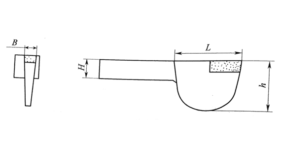
A stepped shaft — thicker where the bending moment is largest, slimmer only where geometry truly requires it — is far easier to machine straight than a uniform-diameter stick. Transitions between steps should be designed with generous fillet radii (typically 1–2 mm minimum, larger on high-stress steps) to spread the stress and avoid creating a stress riser that becomes the seed of chatter.

1.Follower Rests & Steady Rests
A steady rest or follower rest provides physical support to the middle of the shaft during cutting, effectively turning a long, springy part back into something that behaves like a short, rigid part. At VMT, steady rests are deployed as soon as the L/D ratio passes roughly 6:1, with the rest positioned near the cutting zone to cancel the radial component of the cutting force at its source. The contact points are usually bronze or roller bearings, and they are lubricated to avoid marking the finished surface.
2.Reverse Turning / Pull Turning
Conventional turning pushes the tool toward the tailstock, which means the cutting force compresses the workpiece — and slender parts buckle easily under compression. Reverse turning reverses the feed direction so the tool pulls away from the chuck, putting the workpiece into tension. Tension-stiffened shafts are dramatically less prone to deflection, which is why reverse turning is the default for any precision long shaft at VMT.
3.Thermal Management & High-Pressure Coolant
Cutting heat expands the part, and expanded long shafts bow. High-pressure coolant (typically 70–150 bar) does two things at once: it evacuates chips from the cut so the tool does not re-cut them, and it carries heat away from the workpiece fast enough that thermal growth stays within controllable limits. Coolant nozzle position matters as much as pressure — nozzles aimed at the tool–chip interface, not at the part in general, deliver the best results on long slender work.
4.Multi-Pass Turning & Stress Relieving
Trying to take a long shaft from rough stock to final dimension in one or two passes is the fastest way to lock in distortion. The reliable sequence is:
The intermediate stress relieve step is what most shops skip — and it is also what separates parts that hold tolerance over time from parts that drift.
Precision Straightening
Even with every precaution, long shafts occasionally come off the machine with a measured bow above the drawing tolerance. Press straightening between V-blocks with a dial indicator gives a controlled, repeatable correction in the micron range. The shaft is loaded incrementally, measured, and unloaded — usually one or two iterations are enough to bring the runout within spec without inducing new residual stress.
Comprehensive Metrology
Quality Inspection: Long shafts should be checked on a coordinate measuring machine (CMM) for straightness and coaxiality, on a roundness tester for circularity and cylindricity, and on a surface roughness tester for the final finish. For shafts with tight dynamic-balance requirements, balancing is performed on a hard-bearing balancing machine.

A European motion-control customer needed a 316L stainless steel drive shaft with an L/D ratio of 18:1, a straightness callout of 0.02 mm over the full length, and a coaxiality of 0.01 mm between the journals at each end. Two previous suppliers had failed first-article inspection: one part showed visible chatter over the middle third, the other bowed 0.05 mm at the midpoint despite passing every in-process check.
Solution
VMT reviewed the drawing and identified three issues that the previous suppliers had not addressed.
Result
The first article measured 0.012 mm straightness and 0.006 mm coaxiality — both inside the drawing limits, and with a finish Ra of 0.4 µm. The customer released the part to production, and the second-order repeat placed 200 shafts into the line with no further deviations. The process is now the standard flow for all long 316L shafts at the customer's facility.

Preventing deflection in long custom shaft machining is a system problem, not a single decision. The drawing sets the difficulty, the material sets the headroom, and the process determines whether the headroom is preserved or spent. Work well on the designing stage and then find a reliable CNC custom shafts manufacturer is what you can do to avoid this deflection problem. If you have a long-shaft drawing in front of office now, welcome to upload it and our engineers will run a free DFM analysis and respond within one business day.

Q1: What L/D ratio starts to cause deflection problems in shaft machining?
A: Above roughly 8:1, deflection becomes a real concern. Between 8:1 and 12:1, careful process control is sufficient. Above 15:1, active support such as a steady rest is essentially required, and above 20:1, the design itself usually needs to be revisited.
Q2: Can long shafts be stress relieved after rough machining?
A: Yes. A controlled furnace cycle (typically 550–650 °C for steel, soak and slow-cool) between rough and finish turning is one of the most effective ways to neutralize the residual stress that causes long shafts to warp after machining. Aluminum and titanium use lower temperature cycles tailored to the alloy.
Q3: How does reverse turning help with deflection?
A: Reverse turning feeds the tool away from the chuck rather than toward it, which puts the workpiece in tension instead of compression. Slender shafts resist tension far better than compression, so deflection and chatter drop noticeably on the same part and the same machine.
Q4: Besides long shafts, what are the most common custom shaft types?
A: Common specialized custom shafts include:
Q5: Is precision straightening safe for hardened shafts?
A: Yes, when done correctly. Press straightening between V-blocks with a dial indicator applies a controlled elastic deflection and is repeatable to the micron level. For case-hardened or through-hardened shafts above approximately 40 HRC, the pressing force is reduced and the number of iterations increased to avoid micro-cracking at the surface.
Q6: What inspection equipment is used to verify a long custom shaft?
A: Typical equipment includes a coordinate measuring machine (CMM) for straightness and coaxiality, a roundness tester for cylindricity, a surface roughness tester for finish quality, and for shafts with dynamic-balance requirements, a hard-bearing balancing machine. The full inspection report is usually issued as a PDF dimensional layout against the GD&T on the drawing.
The technical information and manufacturing advice shared on the VMT website are for general guidance only. While we strive for accuracy, VMT does not guarantee that the processes, tolerances, or material properties mentioned are applicable to every specific project. Any reliance you place on such information is strictly at your own risk. It is the buyer's responsibility to provide definitive engineering specifications for any production orders. Final specifications and service terms shall be subject to the formal contract or quotation confirmed by both parties.

 +86 15099911516


 Read more