CNC Robotic End Effector & EOAT Components CNC Robotic End Effector & EOAT Components

CNC Robotic End Effector & EOAT Components

Custom CNC machining for robotic end effector and EOAT components including gripper jaws adapter plates tooling frames vacuum manifolds and sensor mounts. VMT supports DFM review critical-interface control CMM inspection and prototype-to-repeat production.

icon Critical EOAT Interfaces Controlled to ±0.005 mm

icon 100% Inspection for Drawing-Defined Critical Features

icon Matched Gripper Jaws Controlled as Functional Pairs

icon DFM Review for Lightweight & Thin-Wall EOAT Structures

icon Critical Fits Verified After Surface Finishing

Upload Your Drawing for a Fast Quote All uploads files are safe and confidential

1 DayPrototyping Machining

2 HoursQuick Quote

0 PcsMinimum Order Qualities

98%Yield

Home / Industry / Robotics / Robotic End Effector Components /

Custom CNC Machined Robotic End Effector & EOAT Components


Robotics CNC Manufacturing Solution

Custom CNC Machined Robotic End Effector & EOAT Components Solutions Factory

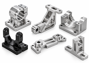
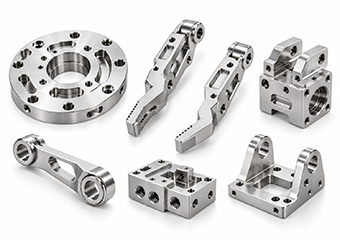
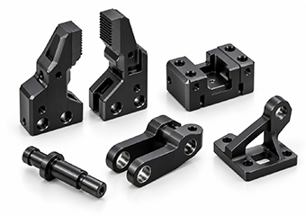
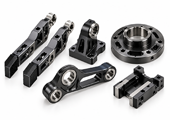
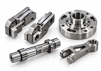
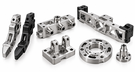
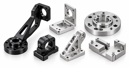
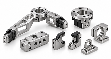
VMT provides custom CNC machining for mechanical components used in robotic end effectors, end-of-arm tooling (EOAT) assemblies and robotic gripper systems. From custom gripper jaws and adapter plates to tooling frames, vacuum manifolds and sensor mounts, we manufacture parts to your drawings with DFM review, multi-axis CNC machining, critical-feature inspection and support from prototype validation through repeat production.

Drawing-Based Custom Machining DFM Review 3 / 4 / 5-Axis CNC IPQC & CMM Prototype → Repeat Production

Have a STEP file, 2D drawing or existing sample? Send your material, quantity, surface finish and critical requirements for engineering review before quotation.

Image Placeholder
custom-cnc-robotic-end-effector-components.jpg
570 × 308
DFM + Fixture PlanningReview functional datums, tool access, lightweight geometry and workholding before machining.
3 / 4 / 5-Axis CNCSelect the machining route according to geometry, feature access and datum relationships.
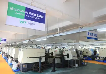
IPQC + CMM InspectionMonitor critical features during machining and verify geometric relationships where required.
Finish + Production SupportCoordinate coating-sensitive fits and support prototype revisions through repeat production.
End Effector Component Family

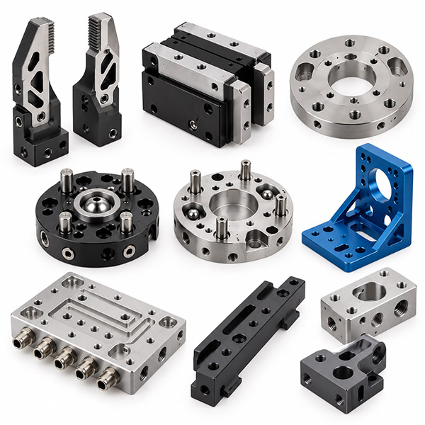
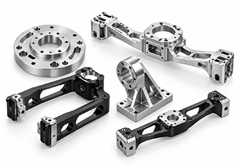
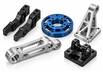
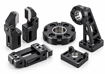
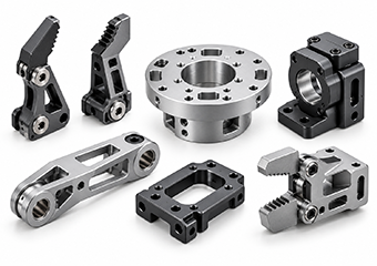
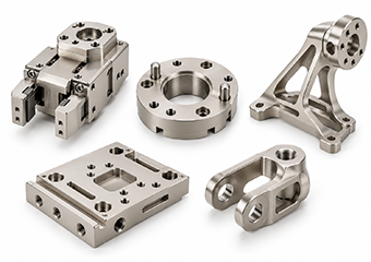
Custom Robotic End Effector & EOAT Components We CNC Machine

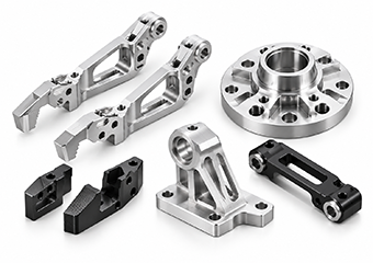
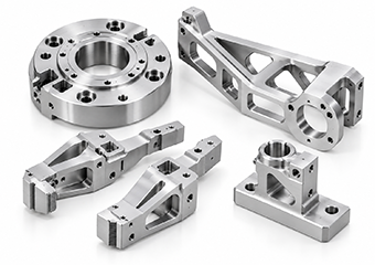
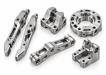
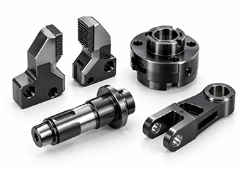
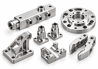
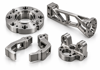
VMT manufactures drawing-defined mechanical components for robotic grippers, EOAT assemblies, tool-changing systems, vacuum tooling and special-purpose end effectors. Each part is reviewed according to its assembly role rather than treated as an isolated CNC component.

Custom CNC Machined Robotic End Effector Components

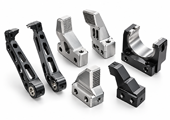
Robotic Gripper Fingers & Jaws

Custom gripper fingers and jaws locate and hold workpieces. VMT reviews mounting datums, paired geometry, contact profiles and machining sequence so the jaw interface and workpiece-contact features remain related after machining and finishing.

Custom CNC Machined Robot Gripper Bodies & Structural Housings

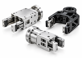
Robot Gripper Bodies & Structural Housings

Gripper bodies support guides, bearings, actuators and mounting interfaces. Deep cavities and multi-side features can create datum-transfer and distortion risks, so VMT plans fixturing around the drawing-defined assembly features.

Custom CNC Machined Robot End-Effector Adapter & Interface Plates

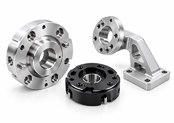
End-Effector Adapter & Interface Plates

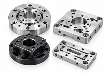
Adapter plates connect robot wrists, tool changers, grippers, sensors and tooling. VMT controls the relationship between mounting faces, bolt patterns, locating holes and tool-side interfaces from the drawing datum scheme.

Custom CNC Machined Robotic EOAT Tooling Plates & Lightweight Frames

EOAT Tooling Plates & Lightweight Frames

Tooling plates and frames support grippers, sensors, vacuum cups and process tooling. Large pockets and thin ribs reduce mass but may increase machining movement, making fixture support and machining sequence important.

Custom CNC Machined Robotic Tool Changer Adapter & Interface Components

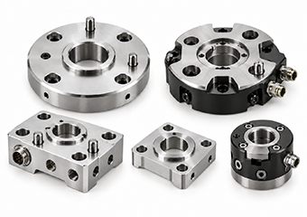
Tool Changer Adapter & Interface Components

VMT machines custom adapter rings, interface plates and related mechanical components where locating features, mounting faces and downstream tooling must stay correctly related.

Custom CNC Machined Robotic Vacuum Manifold Blocks & Suction Mounts

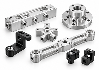
Vacuum Manifold Blocks & Suction Mounts

Vacuum manifold blocks combine pneumatic ports, intersecting passages, O-ring grooves and sealing faces. VMT reviews machining access, burr removal and sealing geometry before release.

Custom CNC Machined Robotic Sensor & Force Torque Sensor Mounts

Sensor & Force/Torque Sensor Mounts

Sensor mounts position force/torque, vision and feedback devices. Hole position, locating faces and adjustment features are machined around the drawing-defined sensor interface and inspection requirements.

Custom CNC Machined Robotic Custom Tool Holders, Brackets & Nests

Custom Tool Holders, Brackets & Nests

Special-purpose EOAT systems may require holders, dispensing mounts, nests and inspection brackets. VMT reviews mating relationships and critical interfaces to define a practical CNC machining and inspection route.

Machining Risk

Critical Interfaces That Can Pass Individual Dimensions but Still Fail EOAT Assembly

End-effector performance depends on mounting patterns, locating features, paired jaw geometry, sealing faces and finish-sensitive fits staying correctly related after machining, re-clamping and surface treatment.

Robot-Side Mounting Patterns & Adapter Faces

Hole positions can pass individually while the plate still tilts or shifts if the bolt pattern, dowels and mounting face are referenced inconsistently.

VMT builds machining and inspection around the drawing-defined robot-side datum and related tool-side interface.
Matched Gripper Finger Geometry

Left and right jaws may each meet isolated dimensions but still contact the workpiece differently if mounting references and profiles are not controlled as a functional pair.

Paired mounting datums, related depths and contact profiles can be reviewed and inspected together when the design requires it.
Lightweight Frames & Thin Sections

Large pockets, ribs and long fingers reduce moving mass but also reduce stiffness during clamping and material removal.

Fixture support and rough-to-finish sequence are planned around the interfaces that must remain stable after release.
Vacuum Sealing Faces & Internal Burrs

O-ring grooves, ports and intersecting channels can fail downstream sealing if burrs, surface damage or groove geometry are not controlled.

VMT reviews channel access, sealing surfaces and deburring before production.
Sensor Mounting & Tool-Side Location

Mounting holes, slots and locating faces must stay related to the intended sensor or tool position after multiple setups.

Datum-based machining and CMM verification are used where the drawing requires relationship-based inspection.
Post-Finish Fit Change

Anodizing, nickel and other finishes can change locating holes, threads, mating faces and contact areas after raw machining has passed inspection.

Masking, finishing allowance and post-finish verification are reviewed before release.
Datum-BasedMachining follows the interfaces that control assembly.
Matched PartsPaired jaw geometry can be treated as one functional set.
CMM When RequiredGeometric relationships are verified to the drawing or inspection plan.
Finish-AwareCritical fits are reviewed in the condition used for assembly.
DFM Before Material Is Cut

DFM Review Before Your EOAT Components Go Into CNC Machining

Before machining, VMT reviews the functional relationships that determine whether your gripper, adapter plate, tooling frame, manifold or sensor mount will assemble correctly. The goal is not only to identify what must be checked, but to define a practical machining and inspection route that can deliver a measurable result.

Functional Datums & Critical Features

We identify which mounting faces, locating holes, jaw references and tool-side interfaces control assembly, then use the drawing datum system to plan machining and CMM verification.

Result: suitable critical dimensions can be controlled to ±0.005 mm after engineering review, and CMM-verified concentricity down to 0.008 mm has been achieved on precision robotic components with relationship-critical geometry.

Machining Access & Setup Planning

Deep pockets, side holes, angled contact profiles and multi-face interfaces are reviewed for tool access before programming so related features can remain in fewer setups where the geometry allows.

Result: VMT selects 3-, 4- or 5-axis machining according to the actual datum relationship; a validated single-setup 5-axis route has reduced fixturing cost by about 40% while also reducing datum-transfer risk.

Wall Thickness & Lightweight Geometry

Large pockets, thin ribs and long gripper fingers are reviewed for clamping support, roughing balance and finish allowance so weight reduction does not create unnecessary machining distortion.

Result: thin-wall machining has been controlled at 1 mm wall thickness, with many machined dimensions held within 8 µm and 0.01 mm concentricity after process validation.

Critical vs. General Tolerances

We separate dimensions that control mounting, gripping, sealing and sensor location from non-critical geometry instead of applying the same tight tolerance everywhere.

Result: machining and inspection effort is concentrated on the features that affect function, while suitable critical features can use VMT's ±0.005 mm machining capability after drawing and geometry review.

Surface Finish Allowance & Masking

Locating holes, dowel features, threads, mating faces, sealing areas and jaw contact zones are reviewed before anodizing, plating or other finishing processes.

Result: masking, pre-finish allowance and post-finish verification can be defined before production, with 100% inspection of specified critical finished features available when required by the quality plan.

Inspection Accessibility

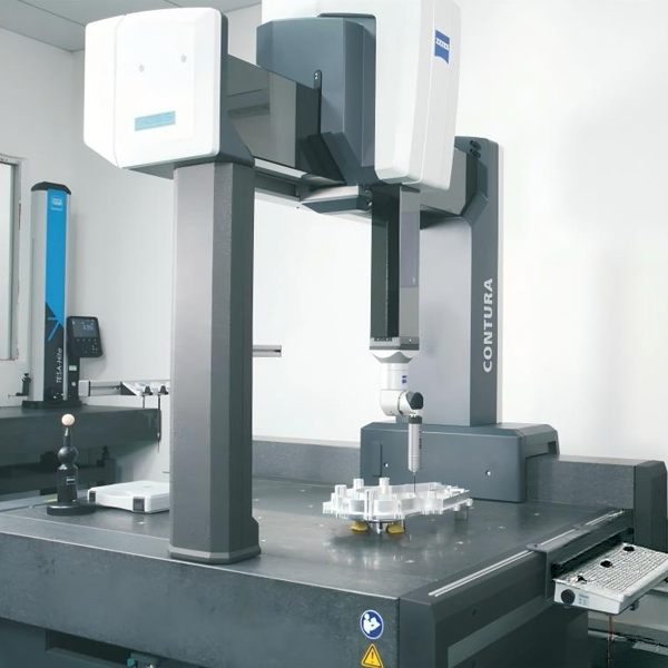
We confirm that the features called out on the drawing can actually be measured after machining and finishing, then match the feature to CMM, gauges, micrometers, height measurement or visual inspection as appropriate.

Result: VMT's 12-step quality-control process can include first-article, IPQC, post-finish and final checkpoints, while project-defined critical dimensions can be 100% inspected.

Process Selection

CNC Machining Strategies for Complex End-Effector Geometry

The process is selected by part geometry, functional relationships, quantity and inspection needs—not by putting every EOAT component on the most complex machine. VMT matches the route to the features that must remain related after machining.

CNC Milling Services

3/4-Axis CNC Milling

Best for adapter plates, gripper bases, tooling plates, sensor brackets and indexed multi-face parts where controlled datums can be maintained without unnecessary 5-axis machining cost.

Best for: plates, brackets, accessible gripper bodies, tooling mounts

5 Axis CNC Machining Parts Services

5-Axis CNC Machining

Used for complex gripper fingers, angled sensor interfaces and multi-face EOAT structures where reducing setup transfers helps protect the positional relationship between mounting, contact and locating features.

Best for: contoured jaws, complex housings, angled interfaces, multi-face parts

Custom CNC Turning Manufacturing Services

CNC Turning / Mill-Turn

Supports interface rings, bushings, pins, shafts and cylindrical adapters that combine concentric bores or shoulders with milled holes, flats, slots or threaded features in one coordinated route.

Best for: interface rings, bushings, pins, compact shafts, threaded adapters

Swiss CNC Machining Services

Swiss CNC Machining

Suited to small pins, guide shafts, sleeves, spacers and threaded cylindrical EOAT components; VMT's published Swiss capability covers Ø0.5–42 mm parts, with ±0.01 mm tolerance available for suitable geometry.

Best for: pivot pins, guide shafts, sleeves, spacers, small threaded components

Fixture Optimization & Staged Roughing

Support points, clamp force and material-removal sequence are planned around lightweight pockets, long fingers and critical mounting features so the part is not forced into tolerance only while clamped and then distorted after release.

Functional Deburring & Edge Control

Pneumatic ports, sealing faces, jaw contact areas, internal passages and assembly edges are reviewed for burr risk; defined internal features can receive 100% visual burr inspection when the project requires it.

Quality Control

Inspection for Critical Robotic End Effector Features

Inspection should prove whether the features that control mounting, gripping, sealing and sensor position will work together in the finished assembly. VMT combines first-article checks, IPQC, CMM and post-finish verification around the released drawing rather than measuring unrelated dimensions only.

±0.005 mmCapability for suitable critical dimensions after engineering review.
12-Step QCIncoming, first-article, in-process, finish, final and outgoing checkpoints.
100%Critical-feature inspection available when specified in the project quality plan.
CMMFor position, datum relationships and geometric verification where required.
IPQC During Machining

Critical bores, mounting faces, hole patterns, jaw references and sealing features can be checked before later operations add cost.

Result: process drift can be corrected before finishing or full-batch completion, reducing avoidable rework.
CMM & Geometric Inspection

CMM is selected for position, perpendicularity, flatness, multi-datum hole patterns and related profiles where basic hand tools cannot prove the required relationship.

Result: CMM verification has achieved 0.008 mm concentricity against a 0.01 mm requirement on precision robotic geometry, giving assembly-critical relationships a measurable acceptance result.
Matched Component Inspection

Paired gripper fingers can be checked from common mounting references, related depths and contact profiles when both parts function as one gripping set.

Result: the inspection plan reflects left/right functional matching instead of accepting two unrelated parts.
Post-Finish & Final Inspection

Locating holes, threads, mating faces and other coating-sensitive features can be verified again after anodizing, plating or other finishing.

Result: specified critical finished features can receive 100% reinspection before shipment.

Inspection Focus by End-Effector Component

Click the table header to expand or collapse the complete inspection matrix. Final acceptance values follow your released drawing and confirmed inspection plan.

ComponentCustomer RiskVMT Verification & EvidenceResult Protected
Gripper Fingers & Jaws
Left and right fingers can meet individual dimensions yet contact the workpiece unevenly because their mounting references or contact profiles do not match as one functional set.
Common-datum review, paired profile/depth inspection and CMM where profile relationships require it; specified critical jaw features can receive 100% inspection.
Protects more consistent paired-jaw position and contact geometry during customer-side gripping validation, reducing adjustment and rework caused by left/right mismatch.
Gripper Bodies
Guide, actuator or jaw interfaces can lose alignment after multi-side machining or repeated setup transfer.
IPQC between setups, datum-based CMM and feature-specific dimensional checks; suitable critical dimensions can be controlled to ±0.005 mm after engineering review.
Reduces assembly correction caused by bore-to-face or setup-transfer errors and helps keep the mechanism aligned to the released drawing.
Adapter & Interface Plates
Robot-side and tool-side patterns can be individually in tolerance but still fail to locate together if the two sides are not controlled from the same datum strategy.
CMM position checks from the drawing datum, flatness/parallelism verification and 100% inspection of specified critical hole patterns or locating features.
Supports smoother robot/tool installation, reduces field rework and protects the intended relationship between the robot-side and tool-side interfaces.
EOAT Tooling Frames
Large lightweight pockets or thin sections can move mounting faces and hole patterns after unclamping, even when the part looked correct in the fixture.
In-process checks are combined with final datum verification after release from the fixture; thin-wall machining has been controlled at 1 mm wall thickness on precision components.
Confirms the frame is accepted in the same released condition used for assembly rather than only while clamped during machining.
Tool Changer Interfaces
Mating faces, pilots or locating holes can create inconsistent engagement if their relationship drifts across separate operations.
CMM or gauges are selected according to the drawing to verify face, pilot and hole-position relationships; project-defined critical interface features can receive 100% inspection.
Protects repeatable mechanical engagement between robot-side and tool-side interfaces and reduces fitting corrections during integration.
Vacuum Manifold Blocks
Sealing-face error, groove variation, thread defects or internal burrs can create leakage, contamination or downstream pneumatic assembly problems.
Seal faces and grooves are measured to the drawing, threads are checked, and defined internal passages can receive 100% visual burr inspection before shipment.
Reduces avoidable sealing and contamination issues before customer-side pneumatic or leak testing.
Sensor Mounts
Hole, slot or locating-face deviation can shift the sensor away from the intended mechanical reference and create calibration or installation adjustment.
Position and face relationships are checked by CMM where required; suitable critical dimensions can be controlled to ±0.005 mm after engineering review.
Supports more repeatable sensor installation relative to the mechanical datum and reduces downstream positioning correction.
Tool Holders & Brackets
Tool orientation or mounting position can shift during assembly if bolt patterns, functional faces or perpendicular relationships are not verified together.
Mounting pattern, perpendicularity and functional-face checks are integrated into VMT's 12-step quality-control flow, with 100% critical inspection available where specified.
Reduces downstream adjustment and helps maintain the tool position defined by the released assembly design.
Material Selection

Materials for Custom CNC Machined Robotic End Effector Components

Material selection affects EOAT moving mass, stiffness, wear, corrosion resistance, contact behavior, surface finishing and cost. If you are not sure which grade fits your design, VMT engineers can review the required load, weight, wear, environment and finishing needs, then recommend a machinable material direction that helps the finished part achieve the properties required for its application.

Custom CNC Machined 6061-T6 Aluminum Robotic End Effector Components

6061-T6 Aluminum

For gripper fingers, adapter plates and tooling frames, 6061-T6 combines low weight, easy machining and anodizing compatibility, delivering cost-effective corrosion-resistant EOAT structures.

Custom CNC Machined 7075-T6 Aluminum Robotic End Effector Components

7075-T6 Aluminum

For compact jaws and high-load adapters, 7075-T6 provides higher strength-to-weight and hard-anodizing compatibility, reducing moving mass while maintaining structural rigidity.

Custom CNC Machined 6082-T6 Aluminum Robotic End Effector Components

6082-T6 Aluminum

For tooling plates, frames and structural brackets, 6082-T6 balances strength, machinability and anodizing compatibility, giving robust lightweight support for industrial EOAT assemblies.

Custom CNC Machined 17-4PH Stainless Steel Robotic End Effector Components

17-4PH Stainless Steel

For high-load mounts, pins and wear-sensitive interfaces, 17-4PH combines strength and corrosion resistance with passivation, supporting durable, dimensionally stable robotic tooling.

Custom CNC Machined 4140 42CrMo Alloy Steel Robotic End Effector Components

4140 / 42CrMo Alloy Steel

For shafts, hardened jaws and torque-loaded interfaces, 4140/42CrMo offers strength and wear resistance with black oxide or plating, improving service durability.

Custom CNC Machined 304 316 Stainless Steel Robotic End Effector Components

304 / 316 Stainless Steel

For corrosion-sensitive brackets, holders and manifold hardware, 304/316 stainless combines toughness with passivation or electropolishing, supporting reliable service in demanding environments.

Custom CNC Machined Titanium Grade 5 Robotic End Effector Components

Titanium Grade 5

For lightweight high-load interfaces, Grade 5 titanium combines specific strength and corrosion resistance with suitable finishing, reducing EOAT mass without sacrificing structural performance.

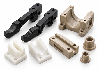
Custom CNC Machined POM PEEK Engineering Plastics Robotic End Effector Components

POM / PEEK Engineering Plastics

For jaw inserts, contact pads, guides and isolators, POM/PEEK provide low friction or temperature resistance with clean machining, protecting workpieces and improving functional isolation.

Surface Finishing

Surface Finishes Without Losing Critical EOAT Fits

Surface finish should be selected from the base material, wear, corrosion, friction, appearance and final fit requirements—not only from color. If you have not finalized the finish, VMT engineers can review the operating environment and critical interfaces, then recommend a practical finishing direction and define where masking, allowance or post-finish inspection is needed.

Custom CNC Machined Type II Anodizing Robotic End Effector Components

Type II Anodizing

For aluminum jaws, plates and frames needing corrosion protection and color; critical holes and mating surfaces are reviewed for masking or final-size allowance.

Custom CNC Machined Hard Anodizing Robotic End Effector Components

Hard Anodizing

For aluminum wear areas needing a harder oxide layer; coating buildup is planned around locating holes, threads, slides and precision fits.

Custom CNC Machined Bead Blast and Anodizing Robotic End Effector Components

Bead Blast + Anodizing

For visible aluminum EOAT structures needing a uniform matte finish; functional surfaces and precision interfaces are protected during blasting and anodizing.

Custom CNC Machined Electroless Nickel Plating Robotic End Effector Components

Electroless Nickel Plating

For suitable metal components needing corrosion and wear protection; deposited thickness is reviewed around bores, grooves, threads and functional mating features.

Custom CNC Machined Passivation and Electropolishing Robotic End Effector Components

Passivation / Electropolishing

For stainless EOAT parts needing improved corrosion resistance or smoother surfaces; electropolishing material removal is reviewed around critical dimensions before release.

Custom CNC Machined Black Oxide Robotic End Effector Components

Black Oxide

For steel jaws, holders and brackets requiring a dark conversion finish with limited dimensional buildup; wear and corrosion requirements are reviewed first.

Custom CNC Machined PVD DLC Coating Robotic End Effector Components

PVD / DLC Coating

For selected wear- or friction-sensitive robotic tooling; substrate, coating thickness and masked interfaces are reviewed so the coating supports durability without losing fit.

Custom CNC Machined Precision Grinding & Lapping Robotic End Effector Components

Precision Grinding & Lapping

For selected shafts, faces, seats and interfaces requiring tighter final geometry or surface condition after CNC machining; used only when the drawing requires it.

Finish-Sensitive Features That Need Engineering Control

These six areas are where a finish can turn an acceptable machined part into an assembly problem. Each control method is tied to a measurable inspection step or a documented process requirement.

Locating Holes

Risk: coating buildup tightens the final fit.

Control: define masking or machining allowance before finishing, then recheck the finished diameter.

Result: suitable critical finished dimensions can be controlled to ±0.005 mm after review; 100% final inspection is available when specified.
Dowel Features

Risk: a small finish change can prevent repeatable dowel engagement or shift the tool-side location.

Control: protect the fit where required and verify the finished feature from the drawing datum.

Result: specified critical dowel features can receive 100% post-finish verification to reduce assembly interference.

Threads

Risk: anodizing or plating can reduce thread engagement or create assembly resistance.

Control: masking, plugging or process allowance is defined before finishing, followed by suitable thread-gauge verification.

Result: critical threads are checked in the finished condition rather than accepted only before coating.

Mating Faces

Risk: added or removed material changes flatness, parallelism or the final interface stack.

Control: protect functional faces where required and verify geometric relationships with CMM or appropriate gauges.

Result: the accepted geometry represents the finished part that actually enters EOAT assembly.

Sealing Faces & O-Ring Grooves

Risk: blasting, coating or burrs can affect surface condition and groove geometry, increasing leakage risk.

Control: inspect sealing geometry, surface condition, threads and internal burrs within the 12-step quality flow.

Result: machined sealing features are verified before customer-side pneumatic or leak testing.

Jaw Contact Areas

Risk: a finish can change friction, contact geometry or mark sensitive workpieces.

Control: define whether the contact zone is coated, masked, ground, lapped or left as-machined, then inspect the related jaw geometry as a functional set.

Result: the finish supports the intended contact condition without unnecessarily changing the gripping interface.

Development to Production

From Robotic End Effector Prototypes to Repeat Production

Custom end-effectors often change after the first assembly or functional test. VMT supports CNC manufacturing through the development cycle so the approved design can transition more clearly into controlled repeat production.

01

Drawing & DFM

Review geometry, material, functional interfaces, tolerance, surface finish and inspection requirements before machining.

02

Prototype Machining

Manufacture the first parts according to the selected CNC route, fixture plan and inspection requirements.

03

Assembly Validation

The customer validates mounting, clearance, gripping behavior, workpiece contact and system-level performance.

04

Drawing Revision

Review changes to jaw geometry, mounting features, weight, material or finish against the latest released drawing.

05

Pilot / Approved Baseline

Establish the released drawing, critical inspection points, fixture references and confirmed manufacturing requirements.

06

Repeat Production

Subsequent orders follow the released requirements, with new revisions reviewed before production begins.

Applications

Applications for Custom CNC Machined End Effector Components

Different robotic tasks place different demands on gripper fingers, tooling frames, adapter plates, manifolds and sensor mounts. VMT manufactures the custom mechanical components inside these systems from your drawings, with DFM, machining and inspection focused on the interfaces that affect the actual gripping, positioning, inspection or process function.

Custom CNC Machined Robotic End Effector Components for Pick-and-Place & Material Handling

Pick-and-Place & Material Handling

Custom jaws, vacuum manifolds, tooling frames and interface plates support part transfer between fixtures, conveyors and processes.

Custom CNC Machined Robotic End Effector Components for CNC Machine Tending

CNC Machine Tending

Part-specific jaws, dual-gripper adapters, sensor mounts and compact tooling structures support automated loading and unloading.

Custom CNC Machined Robotic End Effector Components for Robotic Assembly & Precision Handling

Robotic Assembly & Precision Handling

Precision gripper geometry, sensor interfaces and locating components help present parts consistently during assembly.

Custom CNC Machined Robotic End Effector Components for Packaging & Palletizing

Packaging & Palletizing

Vacuum tooling, lightweight frames, manifolds and mounting structures support application-specific packaging layouts.

Custom CNC Machined Robotic End Effector Components for Inspection, Vision & Quality Testing

Inspection, Vision & Quality Testing

Sensor mounts, camera brackets and force/torque adapters position inspection devices relative to the workpiece.

Custom CNC Machined Robotic End Effector Components for Custom Automation & Special-Purpose EOAT

Custom Automation & Special-Purpose EOAT

Non-standard automation may combine gripping, dispensing, inspection, vacuum handling and process tooling in one mechanical assembly.

Custom CNC Machined 7075-T6 Precision Joint Module for a Collaborative Robot
Robotics CNC Machining Case Study

Case Study: 7075-T6 Precision Joint Module for a Collaborative Robot

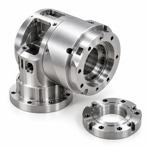
A European collaborative-robot manufacturer required a lightweight 7075-T6 precision module combining a harmonic-drive seat, encoder mounting face and curved internal wire-routing channel in one monolithic housing. The project demanded 0.01 mm concentricity, a housing weight below 180 g, burr-free internal routing and stable multi-face alignment, so DFM, single-setup 5-axis machining, in-process probing and CMM verification were planned as one controlled manufacturing route.

0.01 mmRequired concentricity
<180 gHousing weight target
0.008 mmFinal CMM concentricity
~40%Fixturing-cost reduction from the single-setup route
Project Requirement
A European collaborative-robot manufacturer required a 7075-T6 module combining a harmonic-drive seat, encoder mounting face and curved internal wire-routing channel. The bearing seat and encoder bore had to hold 0.01 mm concentricity while the housing remained under 180 g.
Manufacturing Challenge
The bearing and encoder features had to remain aligned while the curved internal wire-routing channel was machined without burrs that could damage cable insulation during assembly.
VMT Manufacturing Solution
VMT used a single-setup 5-axis route, left 0.3 mm stock during roughing, finished both critical bores with the same boring bar and used in-process probing to correct tool-wear drift before final dimensions were reached.
Inspection & Result
CMM confirmed 0.008 mm concentricity and Ra 0.4 on the critical bearing seat; the wire-routing channel passed 100% visual burr inspection. After a 200-unit validation batch, the customer placed a six-month blanket order.
Customer Trust

What Customers Said After VMT Completed Their Custom Machining Projects

These published customer comments are not presented as EOAT-specific project results. They show what customers said after VMT completed custom machining work: samples were approved, production orders followed, overall service was recognized and customers returned with additional work.

“Your parts were perfect, thank-you. I want to order a production quantity soon.”

Prototype approval leading toward repeat production

“We have now tested the samples and found out that their quality was very good. So, we would like to order a batch of 1000 pcs of each type for our production.”

Sample validation followed by a 1,000-piece production order

“Yes! All is good. Thanks for doing a great job!”

Customer confirmation after project completion

“Products received! Thanks Wendy and the VMT team. We are really happy with the end product.”

Customer message after receiving the completed order
Customer Reviews for Custom CNC Machined Parts Projects
RFQ Preparation

What Should You Send Us for an EOAT CNC Machining Quote?

You do not need a long technical package. Start with the information already available so VMT can understand geometry, critical interfaces, finishing and inspection before quotation.

3D CAD Model

STEP, STP or another common exchange format for geometry, tool-access and multi-side machining review.

2D Drawing

Tolerances, GD&T, datum references, threads and inspection notes where applicable.

Material

Specify the grade or provide application requirements if the material is still under review.

Quantity

Prototype, pilot quantity or the expected repeat-production range.

Surface Finish

Anodizing, plating, passivation or another finish requirement if already defined.

Critical Features / Assembly Context

Identify mounting, locating, sealing, paired-jaw or sensor interfaces and provide mating-part context where useful.

Inspection documentation and special packaging requirements can be added where applicable.

FAQ

Frequently Asked Questions About CNC Machined Robotic End Effector Components

What robotic end effector components can VMT CNC machine?
VMT machines drawing-defined gripper fingers and jaws, gripper bodies, adapter and interface plates, tooling frames, tool-changer interface parts, vacuum manifolds, sensor mounts, tool holders, brackets and nests. The machining route is selected from geometry and function: 3/4-axis for accessible structures, 5-axis for complex multi-face relationships, turning or mill-turn for concentric parts, and Swiss machining for suitable small shafts, pins and sleeves. VMT supports prototype, pilot and repeat production rather than selling standard EOAT products.
Can VMT manufacture custom robotic gripper fingers and jaws from our drawings?
Yes. VMT reviews the gripper-side mounting datum, workpiece-contact profile, finger reach, lightweight pockets, paired left/right geometry and finish-sensitive features before programming. Long or thin fingers can require staged roughing and controlled fixturing to reduce distortion. Where the jaw set has drawing-defined critical features, suitable dimensions can be controlled to ±0.005 mm after engineering review and specified critical features can receive 100% inspection.
Can you machine EOAT adapter and robot interface plates?
Yes. Adapter plates often fail because the robot-side pattern and tool-side pattern are inspected separately even though they function as one interface. VMT builds the machining and CMM plan around the drawing datum structure, checking critical hole position, locating features, mounting faces and related flatness or parallelism where required. This helps reduce assembly correction when the plate is installed between the robot, tool changer, sensor or gripper.
How does VMT control critical mounting and locating features?
VMT first identifies the functional datum instead of tightening every dimension equally. Related holes, dowels, pilots and mounting faces are kept in fewer controlled setups where geometry allows, then verified through IPQC and CMM or suitable gauges. VMT's 12-step quality process supports first-article, in-process, post-finish and final checkpoints, with 100% inspection available for project-defined critical characteristics.
How do you control paired gripper fingers as a matched set?
When left and right jaws work together, VMT does not treat them as unrelated parts. The review focuses on common mounting references, corresponding pocket depths, contact radii, orientation and any drawing-defined matched geometry. The two parts can be inspected around the same datum logic, which helps the customer receive a jaw set that is better prepared for assembly and workpiece-contact validation rather than two individually acceptable but functionally mismatched components.
Which materials are suitable for robotic end effector components, and can VMT help us choose?
Yes. 6061-T6 is a practical lightweight starting point; 7075-T6 or 6082-T6 can provide higher structural performance for selected designs; stainless steels support corrosion resistance; 17-4PH and 4140/42CrMo suit higher-load or wear-related components; titanium reduces mass where its cost is justified; POM and PEEK can protect workpieces or provide isolation. VMT engineers can review load, weight, wear, environment, finish and budget before recommending a machinable material direction.
Can anodizing, plating or coating affect critical EOAT fits?
Yes. Locating holes, dowel features, threads, mating faces and sealing areas can change after finishing even when the raw-machined dimensions passed inspection. VMT reviews masking, machining allowance and post-finish verification before production. For specified finished features, 100% critical inspection can be included so the accepted condition matches the component that actually enters assembly rather than only the part before coating.
Can VMT support prototype validation and then maintain the process for repeat production?
Yes. VMT can support the first prototype, drawing revisions, pilot quantities and repeat orders. After the customer validates the design, the released drawing, fixture references, critical inspection points, finishing instructions and project-specific quality requirements become the manufacturing baseline for later orders. This reduces the risk of an approved prototype being followed by a different production interpretation when quantities increase.
Engineering Guide

Engineering Guide to Custom CNC Machined Robotic End Effector Components

Use this guide when preparing gripper fingers, adapter plates, tooling frames, manifolds and sensor mounts for quotation, prototype validation or production transfer. The purpose is to help you define the features that really affect assembly and avoid adding machining cost without improving EOAT function.

1. Start With the Functional Interface

An end-effector component should be dimensioned around the way it connects to the robot, gripper, workpiece or sensor. On an adapter plate, the important relationship is often between the robot-side datum and the downstream tool interface. On a custom gripper finger, the mounting reference must remain related to the workpiece-contact profile. On a vacuum manifold, sealing faces and O-ring grooves matter more than an unrelated external cosmetic surface.

Before requesting a quote, identify these functional relationships on the 2D drawing. Use datums and GD&T where the relationship matters, and tell the manufacturer which features control the final assembly. VMT uses this information to determine fixture references, machining sequence and inspection method. Suitable critical dimensions can be controlled to ±0.005 mm after engineering review, but applying that level of control everywhere normally adds cost without improving function.
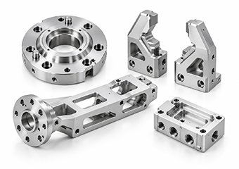
The practical result is a machining plan built around the features the customer actually uses during assembly, not simply around the easiest surfaces for the CNC operator to pick up.

2. Separate Functional Tolerances From General Dimensions

One of the fastest ways to make an EOAT component unnecessarily expensive is to assign tight tolerances to every dimension. A gripper jaw may need close control between its mounting datum and contact pocket, while the outside contour may only provide clearance. An adapter plate may require accurate hole position and face relationship even though many edge dimensions are non-critical.

During DFM, separate CTQ features from general geometry. This allows the machining route, tool selection and inspection plan to concentrate on the features that influence mounting, location, sealing, sensor position or workpiece contact. VMT's 12-step quality process can include first-article, IPQC, post-finish and final checkpoints, and project-defined critical characteristics can be 100% inspected when required.

For buyers, this also makes quotations easier to compare. A supplier that understands which tolerances are functional can explain where machining time and inspection cost are being spent instead of simply pricing every dimension as if it were equally critical.

3. Reduce Weight Without Creating Unstable Thin Walls

Weight is important in end-of-arm tooling because every unnecessary gram moves with the robot. Designers therefore use pockets, ribs and thin sections in gripper fingers, tooling plates and structural frames. The same features that reduce mass can also reduce stiffness during CNC machining.

Deep pockets may release residual stress, long fingers can deflect under cutting force, and thin faces can move when clamping pressure is removed. The manufacturing plan should therefore consider where the part is supported, how material is removed, when critical surfaces are finished and whether a semi-finish or stabilization stage is needed before final machining. VMT has published experience on a 1 mm thin-wall housing project with many dimensions within 8 µm and 0.01 mm concentricity after process validation; those figures are project-specific, but they demonstrate why machining sequence matters when stiffness is limited.
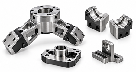
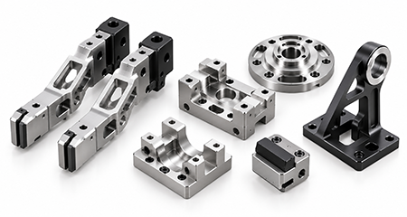
A useful design review question is not simply “Can this wall be machined?” but “Will the nearby functional interface still be stable after the material around it is removed?”

4. Plan Tool Access and Setups Before Freezing Complex Geometry

A CAD model can look compact and elegant while forcing unnecessary manufacturing steps. Deep narrow cavities, small internal corner radii, cross-holes, angled sensor faces and features located on several sides may require long tools or multiple re-clamping operations. Every setup adds another opportunity for datum transfer error.
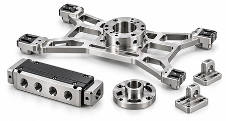
3/4-axis milling is often the most economical route for plates, brackets and accessible housings. 5-axis machining becomes valuable when several functional features lie on different faces and keeping them in fewer setups protects their positional relationship. Turning or mill-turn is better for interface rings, sleeves and cylindrical adapters, while Swiss machining is useful for suitable small pins, shafts and threaded parts.

VMT evaluates the process from the drawing rather than assuming that every complex-looking component belongs on a 5-axis machine. In a published robotics project, a single-setup route reduced fixturing cost by about 40% compared with the previous multi-operation process. The specific saving will vary by part, but the engineering principle is the same: reduce unnecessary transfers while keeping the important features related to the same functional references.

5. Plan Surface Finishing Before Finalizing Critical Fits

Surface finishing should be included in dimensional planning before the CNC program is released. Type II anodizing, hard anodizing, electroless nickel, PVD/DLC and other finishes can change the final size or condition of holes, threads, dowel features, mating faces and contact zones. Electropolishing and grinding can remove material instead of adding it.

For each critical interface, define the condition required after finishing. Decide whether the feature should be masked, plugged, machined with allowance, ground or lapped after coating, or simply verified again in the finished state. VMT can coordinate these requirements with the finishing sequence and include 100% post-finish inspection for specified critical characteristics.

This is especially important on EOAT because the finished component is what goes into the robot cell. Passing inspection before anodizing is not useful if the locating hole becomes too tight or the thread no longer gauges correctly after processing.

6. Design Critical Features for Inspection

A tolerance only helps if the finished feature can be measured reliably. Deep internal pockets, hidden sealing faces, compound-angle profiles and inaccessible datum surfaces can make inspection difficult or force expensive custom gauging. When a feature is function-critical, consider the measurement method during design rather than after the first parts have already been machined.

VMT matches the method to the requirement. CMM is useful for position, perpendicularity, multi-datum hole patterns and related profiles. Bore gauges, micrometers, height gauges and thread GO/NO-GO gauges can be more efficient for suitable features. Visual inspection is important for burr-sensitive internal channels and appearance requirements. A published VMT robotics case used CMM to confirm 0.008 mm concentricity and 100% visual burr inspection on the internal routing channel.

When the drawing identifies the CTQ features clearly, the quality plan can focus on proving the relationships that matter to assembly. This gives engineering and procurement teams more useful evidence than a long dimensional report filled with measurements that do not control function.

Discuss Your End Effector Project
Related Robotics Solutions

Explore Related CNC Machining Solutions for Robotics

Ready to Review Your Robotic End Effector Component?

Send your latest 2D drawing or 3D model with material, quantity, surface finish and critical interface requirements. VMT can review machining access, datum relationships, lightweight geometry, inspection requirements and the prototype-to-production route before quotation.

Customer Reviews

Bluetooth headset charger housing customer
icon icon icon icon icon 2024-08-02

The manufacturer is strongly recommended. In the past few years of cooperation we have ordered several machined products from aluminum and stainless steel. These products are manufactured in compliance with tolerance requirements and require product finish. Now I have ordered another one. The service is excellent and any questions can be answered and resolved in time.

AN Automotive Oil Cooling Joint Customer
icon icon icon icon icon 2021-05-13

The dimensions are all customized according to my drawings no tolerance issues and the parts are delivered on time. I am very satisfied with it.

Flashlight shell machining customers
icon icon icon icon icon 2021-04-06

I pay much attention to the surface treatment aspect of this product. I was a little worried about the cooperation at the beginning. I am very satisfied with the product now and hope to cooperate for a long time.

AN8 Straight PTFE Hose End Fitting
icon icon icon icon icon 2022-09-22

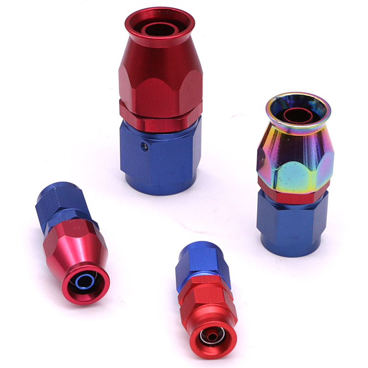
AN8 Straight PTFE Hose End Fitting for PTFE Fuel Line Fitting Adapter Black Blue Red

Upload 2D/3D drawings

Upload Your Files or Contact inquiry@vimetal.com.cn to Get Instant Quote (Please attach 2D CAD drawings and 3D CAD models in any format including STEP, IGES, DWG, PDF, STL, ZIP, etc.).

Upload files ( Max file size: 20MB )
+86 15099911516
loading