16 years one-stop China custom CNC machining parts factory

Hey there I’m VMT Sam!
With 25 years of CNC machining experience we are committed to helping clients overcome 10000 complex part-processing challenges all to contribute to a better life through intelligent manufacturing. Contact us now
 70 |
Published by VMT at Jun 06 2026 | Reading Time:About 4 minutes
70 |
Published by VMT at Jun 06 2026 | Reading Time:About 4 minutes


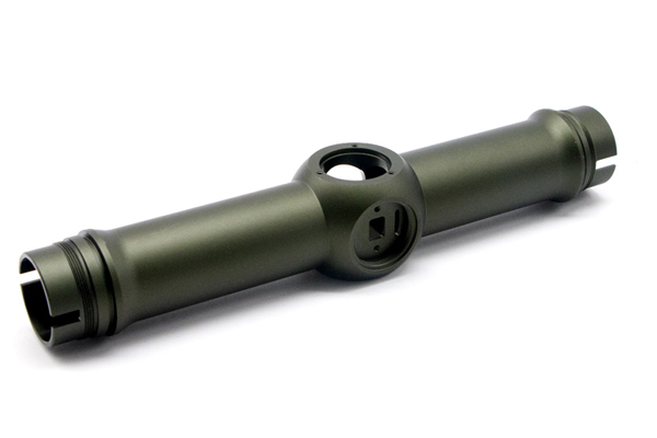
That silky, uniform resistance of a manual focus lens is the ultimate mark of quality. Yet, many flawless blueprint designs end up feeling dry, choppy, or loose after just six months of use. The culprit is right the raw "aluminum-on-aluminum" friction inside the multi-start helicoid threads , which brings the thread galling and wear.
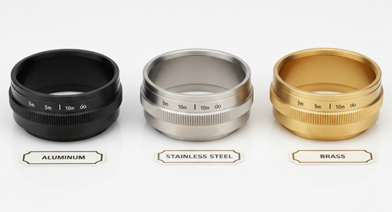
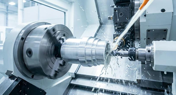
In precision optical CNC machining, aluminum (like 6061/7075) which is lightweight, high rigidity, and excellent machinability is the go-to material; But without surface protection, microscopic metal wear of manual focus quickly turns damping grease into an abrasive paste, ruining the tactile feel.
So, what is the solution? Hardcoat anodizing (MIL-A-8625 Type III) is the industry-recognized standard. It transforms the aluminum alloy surface into a hard, low-friction protective coating. To succeed, you need to master three critical variables: the 50/50 growth rule, pitch diameter compensation, and thread root radius design to prevent edge flaking. In this article, we will break down to overcome the wear issue, followed by a practical case study from our factory shop floor.
The load of multi-start threads is mainly concentrated on the thread flanks. When you turn the focus ring, each flank transmits torque (torsion) while simultaneously enduring significant contact compression (force) and sliding against each other. Without a hard protective layer, the following three wear failure mechanisms occur simultaneously, accelerating thread damage:

1. Surface Adherence Causing Wear (Galling/Microscopic Cold Welding)
The naturally occurring oxide film on the aluminum alloy surface is only a few nanometers thick. Under the high-pressure friction of the thread flanks, this extremely thin oxide film is easily penetrated. Once the unprotected aluminum comes into direct contact, the contact points on the microscopic surface instantly undergo "cold welding." As the focus ring continues to rotate, these tiny weld points are forcibly torn apart, leaving rough score marks on both flanks. Consequently, within just a few weeks, the thread surface is completely destroyed, and the focusing feel quickly shifts from silky smooth to dry and choppy.
2. Shear Fatigue and Plastic Deformation (Thread Crest Wear Leading to Play)
In a 60-degree thread profile structure, the shear stress caused by torque is highly concentrated on the narrow thread crests and contact zones (shear stress: a pair of parallel, equal-sized, and oppositely directed external forces). Although commonly used aluminum alloys like 6061-T6 perform excellently, its shear strength (approx. 207 MPa) still proves insufficient when facing long-term, repeated focusing friction. Over time, continuous shear force causes irreversible plastic deformation of the thread crests, and the crest height gradually wears down. This leads to an increase in axial and radial clearance between the internal and external threads, which manifests to the user as noticeable "looseness" or "backlash" in the focus ring. This is not an assembly issue, but rather physical wear and tear of the thread geometry.
3. Damping Grease Contamination
The core role of damping grease is to provide a smooth, steady, and inertial damping feel for the manual focus ring. However, due to the inevitable wear of the bare aluminum threads, spalled aluminum alloy micro-particles mix into the grease. At this point, the damping grease originally intended for friction reduction becomes contaminated and degrades into an "abrasive paste," accelerating the wear of the threads themselves.

Type III hard anodizing (MIL-A-8625 Type III) is an electrochemical process that transforms the aluminum alloy's own surface into a dense, thick aluminum oxide layer. Unlike Type II decorative anodizing commonly used for cosmetic coloring (which generates a thin and porous oxide layer), Type III hard anodizing can grow a 25–100 μm thick coating to achieve a hard surface.
1. Vickers Hardness Reaches 400–600 HV
The hard layer generated by Type III anodizing can reach a vickers hardness of 400–600 HV. For comparison, the hardness of untreated 6061-T6 aluminum alloy is only about 95 HB (equivalent to around 100 HV). In other words, the surface hardness of the 6061 aluminum after anodizing is directly increased by 4 to 6 times. This high hardness can directly overcome the two major failure modes of uncoated aluminum threads:
2. Ultra-low Friction Coefficient: Creating a "Buttery Smooth Feel"
The dense hard anodized surface has an inherent coefficient of friction significantly lower than that of bare aluminum. When this smooth, high-hardness surface works in tandem with high-viscosity damping grease, it outputs a highly textured, stable, and consistent torque, completely avoiding the stick-slip effect (Stick-Slip). This is precisely one of the causes behind the "buttery smooth feel" of high-end manual focus lenses.
3. PTFE Impregnation (Self-Lubricating Option)
For high-end equipment with the most stringent requirements for focusing feel, type III hard anodizing can also undergo PTFE (polytetrafluoroethylene/Teflon) impregnation treatment. After the hard anodizing is completed, the unsealed porous oxide layer fully absorbs PTFE micro-particles, which are then permanently embedded inside the coating through thermal fixing to form a self-lubricating surface. This solution is specifically designed to solve the instantaneous "sticky sensation" that occurs when turning the lens for the first time after it has been left idle for a period—the embedded PTFE micro-particles can provide boundary lubrication under near-zero speed conditions (i.e., the stick-slip phenomenon where static friction is greater than kinetic friction).
It must be clarified that hard anodizing is a surface conversion coating, rather than a physical coating that simply adheres or overlays onto the aluminum surface. During the electrochemical reaction, as the aluminum alloy is converted into aluminum oxide, approximately 50% of the generated coating thickness penetrates inward into the substrate, while the other 50% grows outward from the original surface.
Taking the application of a 50 µm thick hard anodizing layer as an example, this means:
This "inward and outward" growth characteristic directly changes the geometric dimensions of the part. For a cylindrical hole (internal diameter), a 50 µm coating will cause a 25 µm inward "growth" per side, thereby reducing the overall hole diameter by approximately 50 µm. Conversely, for an external shaft or external thread, its outer diameter will increase by approximately 50 µm.
When dealing with a precision multi-start focus thread with a pitch of only 0.75 mm, the dimensional deviation brought by this 50 µm is unacceptable. If this is not controlled proactively during the machining stage, this unexpected geometric expansion will either cause the internal and external threads to seize up directly during assembly, or completely lock up the operating clearance required for the focus mechanism.
Therefore, in practical production, any precision threads that require hard anodizing must have their compensation amounts strictly pre-calculated during CNC programming and machining. It is suggested to machine the pitch diameter of the external thread smaller, or the pitch diameter of the internal thread larger in advance. This machining compensation amount must not only precisely calculate the surface growth from the "50/50 rule," but must also perfectly factor in the "amplification effect" of the three-dimensional thread tooth geometry.

The growth direction of a hard anodizing layer is always perpendicular to the material surface. At a sharp 90°edge, the oxide layers growing from two mutually perpendicular directions will "collide" at the junction, creating a severe stress concentration zone. Because the hard anodized layer possesses physical characteristics similar to ceramics (high hardness, high brittleness, and a lack of toughness), these edge coatings without substrate support are highly prone to microscopic cracking and brittle flaking under the action of assembly loads or mechanical friction. Once these detached hard ceramic particles mix into the damping grease, the resulting abrasive wear is identical to the consequences of leaving the surface completely untreated.
In precision multi-start focus threads, every thread root and crest is essentially one of these sensitive corners. If the machining process relies entirely on cutting a theoretically sharp V-thread profile, the coating at these sharp corners will crack and flake off during the very first few test assemblies after anodization.
To thoroughly solve this manufacturing challenge, the only solution is to ensure that the thread root and crest possess a built-in radius transition achieved through tooling and programming during CNC thread turning.
In actual production, the minimum radius for the thread root and crest should be controlled at 0.13 mm (0.005''), while the ideal range is 0.25-0.50mm (0.010-0.020''). A continuous rounded surface can evenly distribute the growth stress of the oxide layer across the curved area, thereby perfectly avoiding the flaking caused by stress concentration.
It must be emphasized that this anti-flaking radius must be machined to shape all at once during the CNC thread turning phase; there is absolutely no room for salvage or correction after anodization. This means that during the CNC programming stage, process engineers must holistically calculate and strictly match the tool nose radius (RE value) of the thread turning insert with the full-dimensional compensation of the three-dimensional thread profile.
Not all aluminum alloys perform identically during hard anodizing. The alloying elements contained within the aluminum alloy (especially the content of copper (Cu) and silicon (Si)) directly dictate the density, hardness, and thickness uniformity of the oxide layer.
To help you make the most rational material selection when designing focusing mechanisms, here's a table compared common machining aluminum alloy grades below:
| Aluminum Alloy Grade |
Hard Anodizing Suitability |
Machinability |
Best Application Scenario |
| 6061-T6 |
Excellent. Generates an extremely dense, uniform oxide layer with excellent thickness consistency. It is the industry standard choice for hard anodized optical components. | Good. Stable cutting performance with clean chip breaking. | The vast majority of focusing multi-start threads, general lens barrels, and optical components. |
| 7075-T6 |
Good. Due to a higher copper content than 6061, the microscopic uniformity of the oxide layer is slightly inferior. The appearance color is darker (usually charcoal gray vs. the dark olive green of 6061). | Moderate. Extremely high material strength supports thinner wall thickness designs. | Special multi-start threads requiring ultimate higher structural loads. |
| 2024-T3 |
Poor. A copper content as high as 4.5% leads to an extremely non-uniform coating, easily producing local soft spots or even causing burning during the anodizing process. | Excellent. | Not recommended for precision hard anodized workpieces. |
| ADC12 (Die-Cast) |
Very Poor. The high silicon content of 9-12% cannot undergo electrochemical conversion, resulting in a thin, mottled, and severely discolored coating. | Good castability, but average machinability. | Absolutely prohibited for precision threads. Only suitable for non-sliding structural housings. |
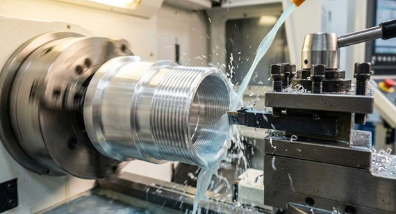
The manufacturing sequence for hard anodized multi-start threads is critical; absolutely no reversal or skipping of steps is permitted.
Step 1: CNC Pre-Compensation Machining (Precision Turning)

Step 2: Pre-Anodization Dimensional Inspection (Proactive Control)
Step 3: Precision Local Masking
Step 4: Type III Hard Anodizing (Core Coating)
Step 5: PTFE Impregnation Treatment (Optional Advanced Self-Lubrication)
Step 6: Post-Anodization Product Verification and Data Closed-Loop
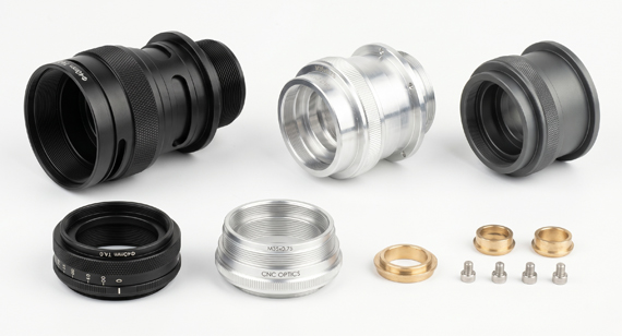
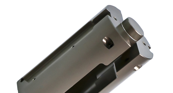
A cinema lens manufacturer needed custom replacement multi-start thread lens barrels for a series of classic manual prime lenses (the OEM had discontinued the component). The design featured a 4-start thread (68mm nominal diameter, 1.0mm pitch) made from 6061-T6 aluminum, requiring a Type III hard anodized coating (50 ± 5µm) with PTFE impregnation.
Core Challenges
The customer's previous supplier delivered parts that galled upon assembly. Our engineering team identified three critical issues:
VMT’s Solution
We proactively implemented three targeted process optimizations:
Project Outcomes

Applying hard anodizing to multi-start threads is a technical challenge that lies entirely at the seamless integration of precision CNC machining and the anodizing process.
When it comes to hard anodized multi-start threads, manual focusing mechanisms, and high-precision lens barrel assemblies, VMT possesses a fully integrated, in-house capability—from frontend precision CNC machining and midstream Type III hard anodizing + PTFE impregnation, to backend full-dimensional closed-loop verification before and after anodization. If you are looking for a manufacturing partner capable of perfectly mastering precision optomechanical components, please feel free to contact us.
【For learning about more comprehensive information about camera lens parts manufacturing, welcome to click and read our technical white paper: The Ultimate Guide to High-Precision Camera Lens Parts Manufacturing. 】

Q1: What thickness of Type III hard anodizing is typical for helicoid threads?
25–75 µm (0.001–0.003") is the standard range. Below 25 µm, the coating is too thin to provide reliable galling protection on loaded thread flanks. Above 75 µm, the pitch diameter compensation (4× the coating thickness) becomes difficult to hold within standard thread fit tolerances. The sweet spot for most manual focus helicoids is 50 ±5 µm.
Q2: Why can't I just use Type II anodizing instead of Type III?
Type II anodizing (decorative anodizing) is typically 5–15 µm thick and has a significantly lower hardness (approximately 200–300 HV vs. 400–600 HV for Type III). On a loaded helicoid thread, Type II wears through within months of regular use. It also provides less galling resistance because the thinner, more porous coating is more easily penetrated under contact pressure. Type II is adequate for external lens barrel surfaces and cosmetic finishes. It is not adequate for sliding thread interfaces.
Q3: Does Type III hard anodizing change the friction behavior of damping grease?
Yes, in a beneficial way. The hard, dense oxide surface provides a more consistent substrate for damping grease than bare aluminum. The grease film remains intact longer because the oxide surface does not shed metallic wear particles. On PTFE-impregnated surfaces, the PTFE provides boundary lubrication that complements the hydrodynamic action of the grease. The combined system (oxide + PTFE + grease) produces lower torque variation across the focus range than any single solution alone.
Q4: Can hard anodized threads be reworked if the coating is too thick?
Not practically. The oxide layer is harder than most cutting tools. Attempting to re-cut a hard-anodized thread will destroy the cutting tool and likely fracture the coating at the edges of the cut. The correct approach is prevention: machine the thread with the correct pre-anodize compensation, control the anodizing process to the target thickness, and verify with GO/NO-GO gauges immediately after anodizing.
Q5: Does PTFE impregnation wear off over time?
PTFE impregnated into a Type III hard anodize coating is embedded within the porous oxide structure and thermally bonded. It does not wear off as a surface-applied coating would. As the oxide surface slowly wears over tens of thousands of focus cycles, new PTFE particles are exposed from within the coating. The self-lubricating property persists for the full service life of the coating.
Q6: What thread tolerances are achievable with hard anodized helicoids?
With proper pitch diameter compensation and process-controlled anodizing, a 6H/6g thread fit (ISO metric) is routinely achievable. Achieving 5H/5g or tighter requires tighter anodizing thickness control (±3 µm) and more frequent CMM verification of both pre- and post-anodize dimensions. For most manual focus applications, 6H/6g provides sufficient precision with practical manufacturing margins.
The technical information and manufacturing advice shared on the VMT website are for general guidance only. While we strive for accuracy, VMT does not guarantee that the processes, tolerances, or material properties mentioned are applicable to every specific project. Any reliance you place on such information is strictly at your own risk. It is the buyer's responsibility to provide definitive engineering specifications for any production orders. Final specifications and service terms shall be subject to the formal contract or quotation confirmed by both parties.

 +86 15099911516


 Read more