16 years one-stop China custom CNC machining parts factory

Hey there I’m VMT Sam!
With 25 years of CNC machining experience we are committed to helping clients overcome 10000 complex part-processing challenges all to contribute to a better life through intelligent manufacturing. Contact us now
 71 |
Published by VMT at Jun 04 2026 | Reading Time:About 3 minutes
71 |
Published by VMT at Jun 04 2026 | Reading Time:About 3 minutes


When specifying a lens barrel, you surely firstly focus on dimensional tolerances — bore concentricity, lens seat depth, thread fit. Those numbers go on the drawing because their effect on performance is obvious: a decentered lens element produces asymmetric MTF—closely related to image quality. But how would think of the surface roughness on an optical housing inner wall?
People tend to assume that a barrel wall with an Ra of 0.4 µm is higher quality simply because it feels smoother than one with an Ra of 1.2 µm, but this is a misconception. An excessively smooth surface reflects light specularly like a mirror, degrading camera image quality, while an overly rough surface causes uncontrolled diffuse scattering and compromises the aesthetic texture. To suppress coherent ghost images and maximize stray light control, the internal surface must fall within the best recommended surface roughness: Ra 0.8–1.6 µm.
This article explains why that range matters, how machining and surface treatment work together to hit it, and what to put on the drawing to ensure the part you get performs the way your optical design assumes.

1.1 Specular vs. Diffuse Reflection
When light hits a surface, what happens depends on the relationship between the surface's roughness features and the light's wavelength. Visible light spans roughly 400–700 nm (0.4–0.7 µm). Near-infrared — relevant for machine vision, LiDAR, and scientific cameras — extends from 700 nm out to about 1,500 nm (1.5 µm).
A lens barrel needs the second behavior. Stray light that reflects specularly off a smooth inner wall can travel straight through the optical path as a focused ghost. The same stray light hitting a properly rough surface scatters into directions that never intersect the sensor.
1.2 The Precision Paradox: Why Super-Smoother Fails
In standard manufacturing, a CNC machining shop considers an Ra 0.2–0.4 µm finish the pinnacle of quality — the smoothest but also highest cost. For an optical housing inner wall, however, this is unnecessary.
At visible and NIR wavelengths, that mirror-smooth surface behaves exactly like glass: photons bounce off it coherently, preserving their direction and producing structured ghost reflections at the sensor.
| Surface Roughness (Ra) |
Reflection Behavior |
Stray Light Consequence |
| <0.4 µm (mirror-like) |
Specular — coherent reflection, predictable angle | High risk: reflections form focused ghost images on the sensor |
| 0.4–0.8 µm (fine satin) |
Mixed — partially specular, partially diffuse | Moderate risk: some ghost structure visible, contrast loss at edges |
| 0.8–1.6 µm (matte) |
Diffuse — scattered in random directions | Low risk: reflected energy distributed as uniform, negligible noise floor |
| 1.6–3.2 µm (coarse matte) |
Diffuse — but surface features are deep enough to trap debris | Low optical risk, but cleaning and particulate contamination become concerns |
| >3.2 µm (coarse) |
Diffuse — but deep, periodic tool marks survive blasting | Optical risk returns: deep, periodic tool marks cause macro-reflection leakage or directional glare at grazing angles |
2. How Ra 0.8–1.6 µm Connects to <1% Reflectivity (for Aluminum Optical Parts)
Achieving a diffuse reflection surface with <1% reflectivity requires a tightly controlled three-step process sequence:
2.1 Substrate Roughness (the Machining Step)
The aluminum surface coming off the CNC machine sets the foundation. The ideal as-machined Ra before surface treatment is 0.8–1.2 µm — at the lower end of the sweet spot — because the subsequent bead blasting and anodizing steps will add their own contribution to the final surface texture.
2.2 Bead Blasting (the Texture Step)
Bead blasting after machining adds the random micro-roughness that breaks up any remaining tool mark patterns. The media, pressure, and dwell time determine the final Ra:
| Blasting Parameter |
Effect on Ra |
Result (Pre-anodize) |
| 180-grit glass bead, 40–60 PSI, full coverage | Adds ~0.3–0.5 µm to as-machined Ra | Shifts Ra 0.8 µm → ~1.1–1.3 µm |
| 150-grit alumina, 50–70 PSI, full coverage | Adds ~0.5–0.8 µm | Shifts Ra 0.8 µm → ~1.3–1.5 µm |
| 200-grit ceramic bead, 30–50 PSI, full coverage | Adds ~0.2–0.4 µm | Shifts Ra 0.8 µm → ~1.0–1.2 µm (finer, more uniform) |
The goal is a random matte texture with no remaining directional tool marks visible under 10× magnification. If tool mark patterns survive blasting, they will produce structured reflections at specific rotation angles relative to the optical axis.
2.3 Anodizing (the Sealing Step)
The anodizing sequence(especially the popular black anodizing) alters surface topology. While the chemical etching phase can slightly smooth out sharp microscopic peaks, the subsequent oxide layer growth typically causes a net shift of ±0.1–0.2 µm in the final Ra. A matte seal (as opposed to glossy nickel acetate) preserves the diffuse character created by blasting. The final Ra after anodizing should land in the 1.0–1.6 µm range.

2.4 The Result
When these three steps are executed as a controlled sequence — machine to Ra 0.8–1.2, blast to random matte, anodize with matte seal — the result is a surface that delivers reflectance ≤0.5% at 660 nm measured at 45° incidence. Getting below 1% is not about one magic number. It is about the system of three steps working together.

Different CNC processes produce different inherent surface finishes. Choosing the right process for the right feature avoids over-processing (paying for Ra 0.4 on a surface that needs Ra 1.2) or under-specifying (getting Ra 3.2 when the optical design needed Ra 1.0).
| Process |
Standard Ra |
Precision Ra |
Best For |
| CNC turning (lathe) |
0.8–1.6 µm | 0.4–0.8 µm | External diameters, simple internal bores — the natural Ra range for turning overlaps with the optical sweet spot |
| CNC 3-axis milling |
1.6–3.2 µm | 0.8–1.6 µm | External housing surfaces, mounting flanges — standard milling Ra is on the borderline; precision parameters needed for optical surfaces |
| 5-axis machining |
0.8–1.6 µm | 0.4–0.8 µm | Complex barrel geometries with side features — 5-axis enables single-setup machining, which also helps maintain the same Ra across all features |
| Swiss-type turning |
0.4–0.8 µm | 0.2–0.4 µm | Small diameters (Φ1–51 mm), deep bores — natural Ra is too smooth for optical scattering; requires deliberate de-smoothing via blasting |
| Single-point diamond boring | 0.2–0.4 µm | 0.1–0.2 µm | Optical seat surfaces that need low Ra for lens seating accuracy — but these same surfaces then need blasting if they are in the optical path |
Manufacturing guideline: For most optical housing inner walls, standard CNC turning or 5-axis profiles naturally align with the Ra 0.8–1.6 µm window. If a machinist defaults to high-precision inserts and slow feed rates, the resulting Ra 0.4–0.6 is too smooth — and must be corrected via bead blasting. For small-diameter barrels produced on Swiss-type lathes, the natural finish (Ra 0.4–0.8) is inherently on the smooth side; bead blasting is mandatory to bring the surface into the diffuse scattering range.
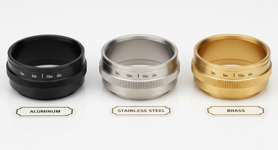
Typically, optical components undergo a blackening surface treatment to achieve low reflectivity. Taking aluminum optical parts as an example, matte black anodizing is the most common approach. Because the black anodize layer itself introduces a specific coating thickness and morphology—where different process combinations yield vastly different results—it inevitably alters the final surface roughness (Ra) of the component. Similarly, for iron-based alloys (such as stainless steel or carbon steel) or copper-based alloys (such as brass), a black oxide process is utilized for blackening. Therefore, to consistently achieve <1% reflectivity, you must design for the combined system of the machined part + coating.
4.1 Matte Black Anodizing on Aluminum (Controlled-Ra)
For aluminum substrates, pairing the correct machine profile with matte black anodizing yields the lowest possible reflectivity. However, the multi-step process shifts the surface profile at each stage.
| Substrate Ra (As-Machined) |
After Blasting + Matte Anodizing |
Reflectance (660 nm, 45° Incidence) | Optical & Mechanical Consequence |
| <0.4μm (Too Smooth) | Final Ra~ 0.6–0.8μm | 1.0% - 2.0% | Borderline Failure: Retains a strong specular component; high risk of ghost images. |
| 0.8–1.2μm (Target) | Final Ra~ 1.0–1.6μm | <= 0.5% | Optimal Window: Uniform diffuse matte scattering with negligible noise floor. |
| 1.6–2.0μm (Upper End) | Final Ra~ 1.8–2.5μm | <= 0.5% | Mechanical Risk: Optically fine, but the deep micro-valleys trap lint and shed particulates. |
| >3.2μm (Too Rough) | Final Ra > 3.0μm | 0.5% - 1.5% | Structured Glare: Visibly textured; underlying periodic tool marks cause directional leakage. |
4.2 Black Oxide on Iron/Copper-Based Alloys
Unlike the deep, dye-absorbing porous layer of anodization, the black oxide process generates a much thinner chemical conversion layer (typically 0.5–1μm of magnetite or copper oxide). This layer conforms precisely to the substrate’s topography, meaning the pre-treatment Ra dictates the final Ra.
| Substrate Ra (Post-Blasting) |
Black Oxide Visual Result |
Reflectance (660 nm, 45° Incidence) |
| 0.4μm (Fine Substrate) | Semi-matte / Semi-specular sheen | 3.0% - 5.0% |
| 0.8μm (Medium Substrate) | Satin finish; directional tool marks remain visible at grazing angles | 3.0% - 5.0% |
| 1.6μm (Coarse Substrate) | Matte satin; maximizes diffuse scattering for this material | 3.0% - 4.0% |
Noting:

A complete drawing specification for an optical barrel surface should address three things: the target Ra, the process sequence, and the verification method.
Recommended Drawing Callout
For internal bore surfaces that are in the optical path:
On the Engineering Drawing:
"Machine internal bore to Ra 0.8–1.2 µm. Do not polish. Bead blast (180-grit glass bead, 40–60 PSI) to uniform matte finish. Black anodize per MIL-A-8625, Type II, Class 2 (Matte/Non-specular seal), thickness 15 ± 5 µm. Final surface roughness to be Ra 1.0–1.6 µm."
In the Quality Assurance (QA) Spec:
"Verify optical performance via spectrophotometer on a sample coupon: Reflectance ≤0.5% at 660 nm (45° incidence)."
Key Points to Communicate to the Shop
——Fixing a Stray Light Problem by Adjusting Ra
A LiDAR developer was qualifying a new 6061 aluminum lens barrel for a 905 nm pulsed laser receiver. The barrel met all dimensional specifications: bore concentricity ≤10 µm, lens seat depth ±5 µm, threads to class 6H. The finish was called out as "matte black anodize."
First-article barrels passed mechanical inspection but failed stray light testing — the receiver's noise floor was higher than the optical budget allowed, reducing detection range by approximately 15%.
What was found:
The as-machined Ra on the internal bore was 0.3–0.5 µm. The clients’ previous shop had used a fine-finish turning insert and a slow feed rate — standard practice for "precision" work. While bead blasting was applied, it merely superimposed a superficial texture over an inherently reflective, ultra-smooth base. The post-anodized surface landed at an inadequate Ra 0.6–0.8 µm, failing to scatter the high peak power of the 905 nm laser. Even a small specular fraction from that smooth underlying substrate produced measurable noise in the receiver.
VMT Solution and Result:

The Ra 0.8–1.6 µm window is not an arbitrary target. It is the range where visible and near-infrared light interact with an anodized aluminum surface in a way that scatters instead of reflects — diffuse instead of specular, random instead of structured. Below this range, the surface trends toward mirror behavior even if the dye is black. Above it, machining artifacts create their own problems.
Three things to remember:
Welcome to Contact VMT today to review your drawings and optimize your optical housing inner walls before your first production run.
【For learning about more comprehensive information about camera lens parts manufacturing, welcome to click and read our technical white paper: The Ultimate Guide to High-Precision Camera Lens Parts Manufacturing. 】

Q1: Why not just specify the smoothest possible surface? Wouldn't that be better?
No. A very smooth surface (Ra <0.4 µm) behaves as a mirror at optical wavelengths — it reflects specularly, producing coherent ghost images rather than diffuse scatter. For stray light control, the surface needs controlled roughness to break up the specular reflection path. "Smooth = better" is correct for mechanical fit and seal surfaces. For optical cavity surfaces, it is backwards.
Q2: Can Ra 0.8–1.6 µm be achieved on internal bores, or only on external surfaces?
Internal bores can achieve Ra 0.8–1.6 µm with standard turning or boring operations. The bore diameter determines tool access: bores above ~10 mm diameter can be single-point bored or turned directly. Below ~10 mm, specialized small-bore boring bars or Swiss-type turning may be needed. Bead blasting of internal bores requires a nozzle that can reach inside — for deep bores (length-to-diameter ratio >5:1), this requires a right-angle blast nozzle and may limit the achievable uniformity.
Q3: Does bead blasting change the bore diameter?
No, glass bead blasting does not remove material — it peens and deforms the surface microscopically. However, the pre-anodize chemical etching (acid/alkaline dip) will strip roughly 2–4 µm of aluminum. This material loss is then offset by the anodic oxide growth (~7–8 µm outward per surface). The combined sequence (machine → blast → etch → anodize) is a standard process with predictable dimensional offsets.
Q4: What happens to Ra after anodizing? Does the coating make it smoother or rougher?
Anodizing typically adds 0.1–0.3 µm to Ra because the oxide layer grows with a slightly irregular surface profile. A matte sealant preserves this texture. A glossy sealant (such as standard hot nickel acetate) promotes smooth, hydrated crystal growth over the pores, effectively leveling the micro-peaks and reducing Ra by 0.1–0.2 µm. This creates an unwanted semi-specular sheen — smoothing out the very texture that produces diffuse scattering. This is why the sealant type matters: matte seal for optical barrels, glossy seal only for cosmetic external surfaces.
Q5: Can black oxide achieve <1% reflectance if the surface roughness is controlled?
No. Black oxide's reflectance floor is set by the material properties of magnetite (Fe₃O₄), not by surface roughness. Even on an optimally rough surface, magnetite reflects 3–5% of visible light and 5–10% at NIR wavelengths. Roughness control can make the reflection more diffuse (less structured, less likely to form ghost images), but it cannot reduce the total reflected energy below the material's intrinsic reflectance. The <1% threshold requires the combination of aluminum oxide + organic dye + controlled roughness that only black anodizing provides.
Q6: Is Ra the right roughness parameter for optical surfaces, or should I use something else?
Ra (arithmetic average roughness) is the most commonly available parameter and is adequate for process control. However, for optical surfaces, two additional parameters are useful:
For most production specifications, Ra supplemented by a visual check for directional tool marks (no patterns visible under 10×) is sufficient. If the system operates at a specific NIR wavelength, adding an Rz specification becomes more important.
The technical information and manufacturing advice shared on the VMT website are for general guidance only. While we strive for accuracy, VMT does not guarantee that the processes, tolerances, or material properties mentioned are applicable to every specific project. Any reliance you place on such information is strictly at your own risk. It is the buyer's responsibility to provide definitive engineering specifications for any production orders. Final specifications and service terms shall be subject to the formal contract or quotation confirmed by both parties.

 +86 15099911516


 Read more