15 years one-stop China custom CNC machining parts factory

Hey there I’m VMT Sam!
With 25 years of CNC machining experience we are committed to helping clients overcome 10000 complex part-processing challenges all to contribute to a better life through intelligent manufacturing. Contact us now
 96 |
Published by VMT at Mar 01 2026 | Reading Time:About 2 minutes
96 |
Published by VMT at Mar 01 2026 | Reading Time:About 2 minutes


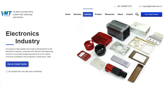
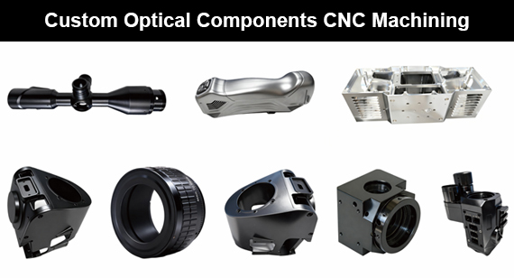
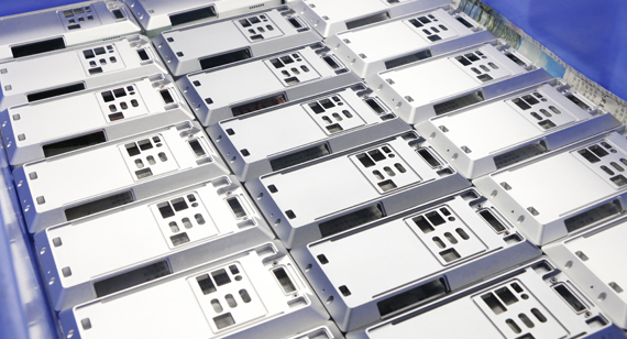
For a wide range of electronic products, an enclosure serves as much more than just a physical barrier to protect against dust, impacts, or scratches. While these functions are undoubtedly essential, there is another critical requirement that cannot be overlooked: managing the signal interference—both emitted and received—by the electronic components within. This is precisely why aluminum for CNC-machined electronic enclosures are so highly sought after; aluminum as a material naturally possesses excellent electromagnetic shielding properties. Electromagnetic shielding is not limited to electronic enclosures; it is a vital consideration in many uses from aerospace components designed to prevent radar interference to the infrastructure of telecommunication base stations or for precision medical equipment. Understanding the basics of electromagnetic shielding, good shielding materials, and recognizing the unique advantages of CNC machining in producing metal components with good shielding capabilities will provide values for your engineering design and manufacturing requirements.


Electromagnetic Shielding is the technical process of isolating a specific volume of space from external electromagnetic fields or preventing internal electromagnetic energy from escaping. This is achieved by placing a barrier made of conductive or magnetic materials between the source of the interference and the electronics that need protection.
The primary objective is to manage EMI (Electromagnetic Interference) to ensure EMC (Electromagnetic Compatibility).
In practical manufacturing, such as CNC-machined aluminum enclosures, the metal housing acts as a Faraday Cage, which blocks external static and non-static electric fields by neutralizing the internal field through the redistribution of electric charges on the conductor's surface.
How Does It Work?
The effectiveness of an electromagnetic shield depends on three physical mechanisms that attenuate (weaken) the energy of an incident electromagnetic wave:

Table 1: Mechanism of Electromagnetic Shielding
| Mechanism |
Physical Explanation |
Controlling Factors |
| Reflection |
When an electromagnetic wave hits the shield, the impedance mismatch between the air and the metal surface causes most of the energy to reflect back. | High Electrical Conductivity (e.g., Aluminum, Copper). |
| Absorption |
Energy that is not reflected enters the material and is converted into heat. This occurs as the wave interacts with the atoms of the shield. | Thickness and Magnetic Permeability. |
| Multiple Reflections |
This describes the internal reflections within the shielding material. It is typically a correction factor for very thin materials or high-frequency scenarios. | Material structure. |
For high-frequency shielding, Reflection is the dominant factor and requires high conductivity. For low-frequency magnetic fields, Absorption is the primary mechanism, which depends heavily on the Magnetic Permeability of the material to "trap" and dissipate magnetic flux.
The selection of shielding materials is determined by the frequency of the interference, the required attenuation level, and the manufacturing process.
Aluminum (e.g., aa6061, aa7075):
Aluminum is the most common material for CNC-machined electronic enclosures. It offers excellent Conductivity, which provides high reflection-based shielding for high-frequency signals. It is lightweight, corrosion-resistant, and ideal for machining complex features like Tongue-and-Groove structures to prevent Gap Leakage.
Copper and Brass:
These materials offer higher conductivity than aluminum, providing superior shielding effectiveness for extremely sensitive RF (Radio Frequency) applications. However, they are heavier and more expensive.
Stainless Steel and Cold Rolled Steel:
While less conductive than aluminum, steel has higher Magnetic Permeability. This makes it more effective at absorbing low-frequency electromagnetic interference (magnetic fields) where aluminum might fail. Cold rolled steel provides much better magnetic permeability to absorb these fields due to it flattens and aligns the internal grain structure of the metal. It is like a massive iron pipe (the field enters the pipe wall and follows the metal around the room instead of going through the center).
High-Permeability Alloys (e.g., Mu-Metal):
These specialized nickel-iron alloys are engineered specifically for maximum Magnetic Permeability. They are used in high-precision aerospace or scientific instruments to block static or low-frequency magnetic fields that standard metals cannot stop.
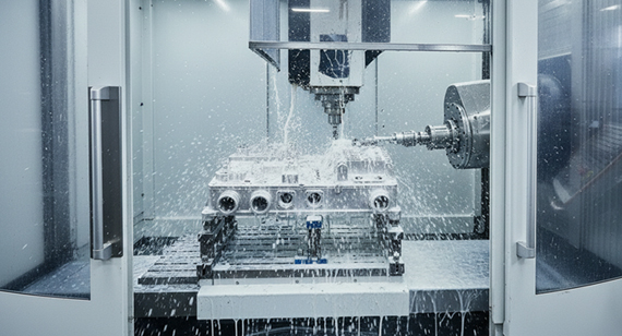
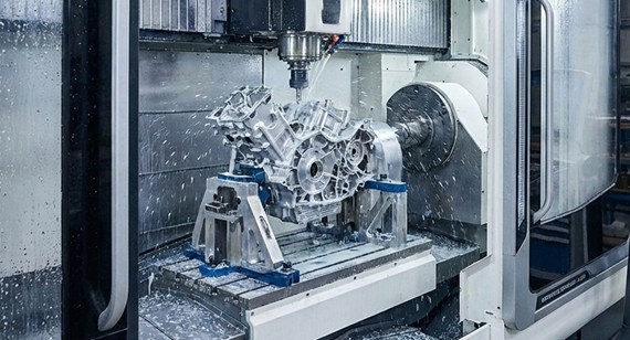
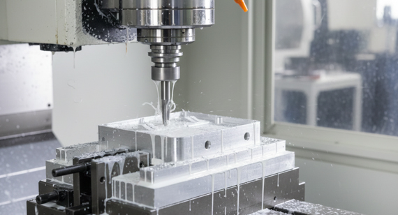
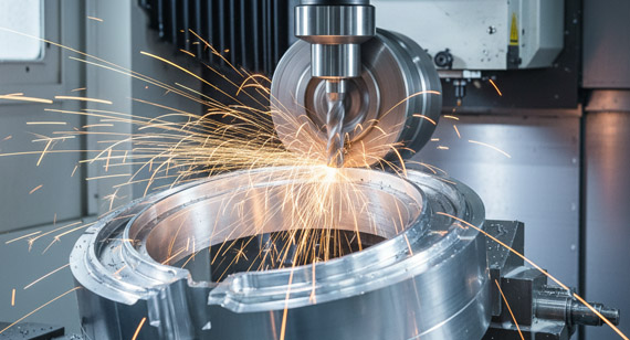
CNC machining is often the preferred manufacturing process for high-performance electromagnetic shielding due to its ability to maintain structural integrity and extreme dimensional precision. This manufacturing process is cutting, drilling ,milling a piece of material into designed shape and it is controlled by computer programs; so the micron-level tolerances can be perfectly achieved.

Micron-Level Tolerances and Waveguide Leakage Prevention
As signal frequencies increase (such as in 5G or satellite communications), wavelengths become shorter. These high-frequency waves can easily "leak" through microscopic gaps in an enclosure—a phenomenon known as Slot Leakage. CNC machining provides micron-level tolerances (often ±0.01mm or tighter), ensuring that the mating surfaces between a housing and its cover are perfectly flush. This minimizes the gap size to well below the critical fraction of the wavelength required to prevent leakage.
Example: High-Frequency RF Enclosures
In a 28 GHz millimeter-wave application, the wavelength is approximately 10.7 mm. To maintain high shielding effectiveness (SE), any mechanical gap must be significantly smaller than 1/20th of the wavelength (approx. 0.5 mm). If a casted or poorly machined part has a slight warp of 0.1 mm over a long seam, it can act as a slot antenna, radiating energy outward. CNC machining eliminates this risk by ensuring perfectly flat mounting flanges and precise Tongue-and-Groove joints that force the wave to attenuate through a complex path.
A high-performance shielding material like aluminum can fail if the mechanical design does not account for electrical continuity and wave physics. Below are the most common pitfalls and their engineering solutions.
Table 2: Common Pitfalls in Shielding Design and the Solution
| Design Feature |
Common Pitfall |
Engineering Solution |
| Heat Dissipation / Ventilation |
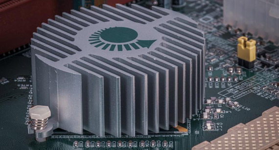
Using large rectangular slots for airflow, which act as "windows" for electromagnetic waves to pass through. | Use an Array of Small Circular Holes. If the hole diameter is much smaller than the wavelength, and the depth of the hole (wall thickness) is sufficient, it acts as a Waveguide Beyond Cutoff (WBC), blocking the signal while allowing air to flow. |
| Surface Treatment |
Applying Anodizing to the entire part. Anodized layers are aluminum oxide, which is an electrical insulator. | Use Conductive Chromate Conversion Coatings (e.g., Alodine/Chem-film). Alternatively, mask the mating flanges during the anodizing process to ensure a metal-to-metal conductive path remains between the housing and the lid. |
| Cover Plate Joints |
Insufficient fastening or large distances between screws, leading to "bowing" and gaps between the lid and the body. | Implement Tongue-and-Groove interfaces or utilize Conductive EMI Gaskets. Ensure screw spacing is tight enough to maintain constant compression and low contact resistance across the entire seam. |
This article introduces the fundamental principles of Electromagnetic Shielding, the critical role of material selection, and the advanced design strategies required to achieve high shielding effectiveness. It is essential to recognize that effective shielding is not just about material choice; it is a complex systematic engineering challenge. Achieving optimal performance—especially at high frequencies—requires the integration of precise mechanical design and micron-level manufacturing of CNC Machining.

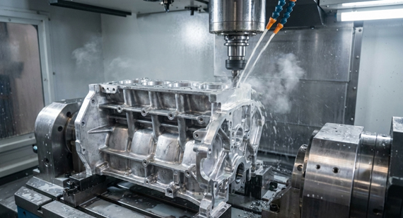
VMT CNC Machining Factory recently completed the production of a 6061-T6 aluminum alloy shielding enclosure for a telecommunications equipment provider’s 28GHz high-frequency signal module. The core objective of this project was to resolve electromagnetic isolation challenges within a multi-cavity structure under ultra-high frequency conditions. Since high-frequency electromagnetic waves leak easily through minute gaps, the design required extreme flatness on the mating surfaces to ensure a fully closed conductive loop once the conductive gaskets were assembled.
During the manufacturing process, VMT utilized high-precision 5-axis CNC machining centers to strictly control the flatness tolerance of the mating surfaces within ±0.02mm. To address the requirements of the high-frequency "skin effect," the technical team optimized cutting parameters to maintain an internal surface roughness of Ra 0.8μm, thereby reducing impedance loss during high-frequency signal transmission. Additionally, deep grooves and isolation walls within the cavities were precisely milled to ensure physical isolation and electrical independence between different circuit units.
The final delivered shielding enclosures passed both conductivity and salt spray testing. The surface treatment employed a conductive chromate conversion coating, which provided corrosion resistance while maintaining low contact resistance. Client testing confirmed that the enclosures met the required shielding effectiveness standards for the target frequency band while providing stable thermal performance.

Q: Why is a CNC-machined shield superior to a sheet metal shield?
A: The primary advantage is structural integrity and continuity. Sheet metal enclosures are often bent and welded, which can lead to gaps at the corners and seams. CNC machining carves the housing from a single solid block of metal, ensuring a seamless, monolithic structure. This eliminates potential leakage paths and provides much higher mechanical rigidity, which is essential for maintaining consistent contact pressure on EMI gaskets.
Q: What are the most common materials used for EMI shielding?
A: Aluminum and Copper are the industry standards. Aluminum (such as 6061) is the most popular for CNC machining enclosures due to its excellent strength-to-weight ratio and high conductivity. Copper offers even higher conductivity and is used for extreme high-performance shielding, though it is heavier and more susceptible to oxidation unless plated.
Q: How do you calculate the required thickness of a shielding box?
A: The calculation must account for the Skin Effect.To ensure effective absorption, the shield thickness should typically be at least 3 to 5 times the skin depth at the lowest target frequency.
Q: Does surface treatment affect shielding effectiveness?
A: Yes, significantly. Shielding relies on low contact resistance and electrical continuity. Standard non-conductive anodizing creates an insulating oxide layer that blocks electrical flow between parts. For shielding applications, Conductive Chromate Conversion Coatings (Chem-film/Alodine) must be used, or mating surfaces must be masked to ensure metal-to-metal contact.
Q: What are the special CNC requirements for high-frequency applications (e.g., above 24GHz)?
A: At frequencies above 24GHz, Surface Roughness (Ra) becomes a critical factor. Because of the skin effect, high-frequency signals travel only on the very "skin" of the metal. If the surface is too rough, the path length increases, leading to higher resistive losses and decreased shielding efficiency. Precision CNC finishing is required to achieve a smooth surface profile that minimizes these losses.
Q: How do you prevent electromagnetic leakage through screw holes?
A: Screw holes should be placed outside the primary shielding seal area. If that is not possible, the design should incorporate a CNC-machined groove for a conductive gasket that surrounds the internal electronics, effectively isolating the screw holes from the shielded cavity.

 +86 15099911516


 Read more